
RF Front-End Module
Design & customization
Explore front-end customization for amplification, attenuation, filtering, switching and receiver protection. MTT Innovations helps turn your RF requirements into a focused module specification.

Control the signal.
Optimize the RF path.
A front end must balance gain, linearity, noise, isolation and protection within a defined power and thermal budget. Discuss the building blocks that your application needs and the interfaces that connect them.
A starting point.
Your application comes next.
Explore the published reference hardware below, then discuss the changes your system needs.
Integrated RF switch & amplifier
An S-band multi-channel reference bringing switching, amplification, digital step attenuation and balun functions together.
- S-band operation
- Multiple RF channels
- Stored configuration settings
- Standalone operation

Multi-channel RF amplifier
An S-band amplification reference for applications that need multiple RF paths and retained settings.
- Multiple amplifier channels
- S-band operation
- Stored settings; standalone operation

Multi-channel RF attenuator
An S-band reference for managing signal levels across several RF paths.
- Multiple attenuation channels
- S-band operation
- Stored settings; standalone operation
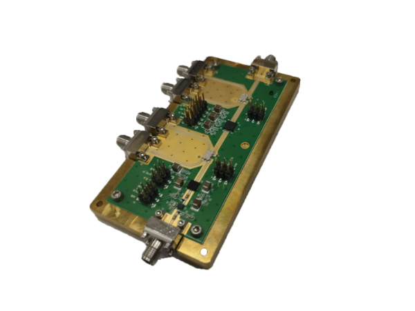
C-band GaN amplifier · 60 W class
A GaN power-amplifier reference with a published output condition for initial system-level review.
- C-band frequency coverage
- Published output: 48 dBm
- Specified RF input: 0 dBm
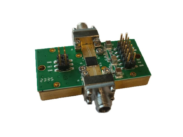
6–9 GHz GaN amplifier · 10 W class
A compact GaN amplifier reference for reviewing microwave amplification requirements.
- Frequency coverage: 6–9 GHz
- Published output: 40 dBm
- Multiple physical variants listed

S-band RF coupler
A coupling-function reference for an S-band RF path.
- S-band reference
- Coupling and loss targets to be defined

S-band RF limiter
A limiter reference for discussing RF input protection in an S-band system.
- S-band reference
- Threshold and power handling to be defined

S-band low-pass & band-pass filters
Filter references for defining the wanted passband and out-of-band attenuation of an S-band signal path.
- Low-pass and band-pass options
- Passband and rejection targets to be defined
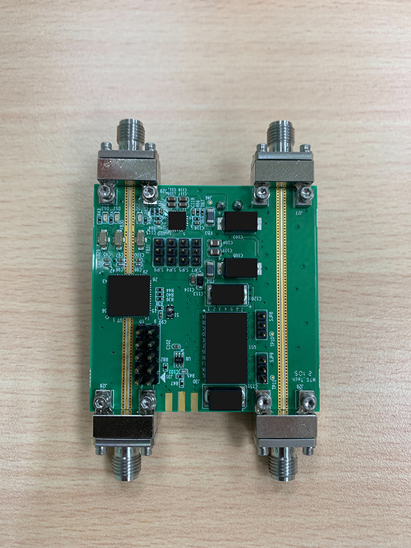
S-to-Ku-band digital filter module
A filter-module reference listed for S-to-Ku-band applications. Detailed performance should be reviewed for the selected requirement.
- S-to-Ku-band reference
- Detailed electrical specifications on enquiry
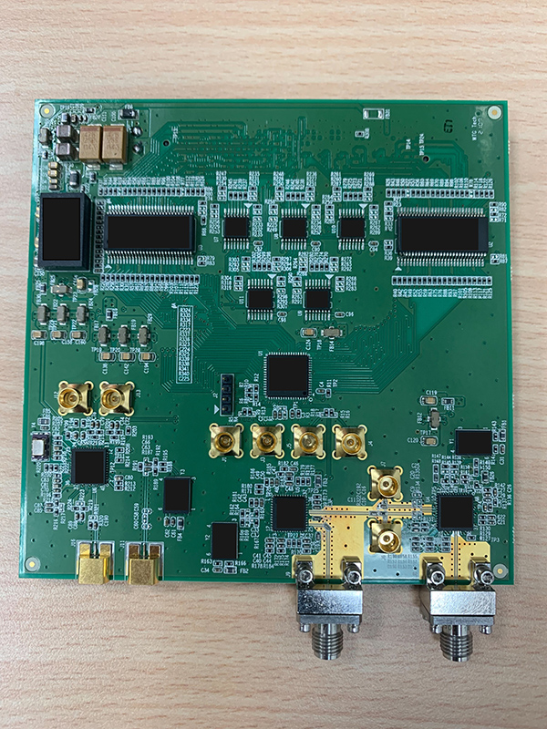
4–10 GHz receiver
A receiver reference listed for the 4–10 GHz range, suitable as a starting point for a tailored receive-chain discussion.
- Listed range: 4–10 GHz
- Gain, noise and bandwidth to be confirmed
Specifications shown describe the individual reference designs, not every custom configuration. Final performance, interfaces and deliverables are agreed after technical review.
Define what your system needs.
Signal conditioning
Define filtering, attenuation and switching functions alongside insertion-loss and isolation targets.
Amplifier requirements
Specify operating band, output power, gain, linearity, duty cycle and thermal conditions.
Receiver protection
Discuss limiter and coupler functions, input levels and receiver sensitivity requirements.
Control & packaging
Review digital control, stored settings, standalone operation, connector layout and shielding.
Tell us what
success looks like.
Share the details you have, along with your target schedule and expected volume. We can use them to structure a technical discussion and identify the points that need further review.
Opens your email app with a ready-to-complete brief.
- 01Operating band and signal bandwidth
- 02Input/output levels, gain and power targets
- 03Noise figure, linearity, isolation and loss limits
- 04Switching, attenuation and control requirements
- 05Duty cycle, thermal design and enclosure constraints
From requirement to an agreed scope.
Share the application
Outline your signal chain, performance goals and integration constraints.
Assess the options
Review reference architectures and the feasibility of requested changes.
Set the project scope
Confirm specifications, engineering deliverables, commercial terms and schedule.
Plan the evaluation
Agree any prototype, test and acceptance activities required for the project.
Do all modules support the same frequency range?
No. The reference designs cover different bands and functions. Choose a starting point by its own published description, then review the required operating range with MTT.
Can switching, amplification and attenuation be combined?
An integrated reference combines RF switching, power amplification, digital step attenuation and a balun. Your channel count, performance and control requirements determine the feasible integration scope.
What information is needed for a quotation?
Send the technical brief, expected quantity, required deliverables and target schedule. Pricing and lead time depend on the agreed design, customization and evaluation scope.
Your requirement.
Our next conversation.
Connect with MTT Innovations to discuss rf front-end module design, customization and integration.