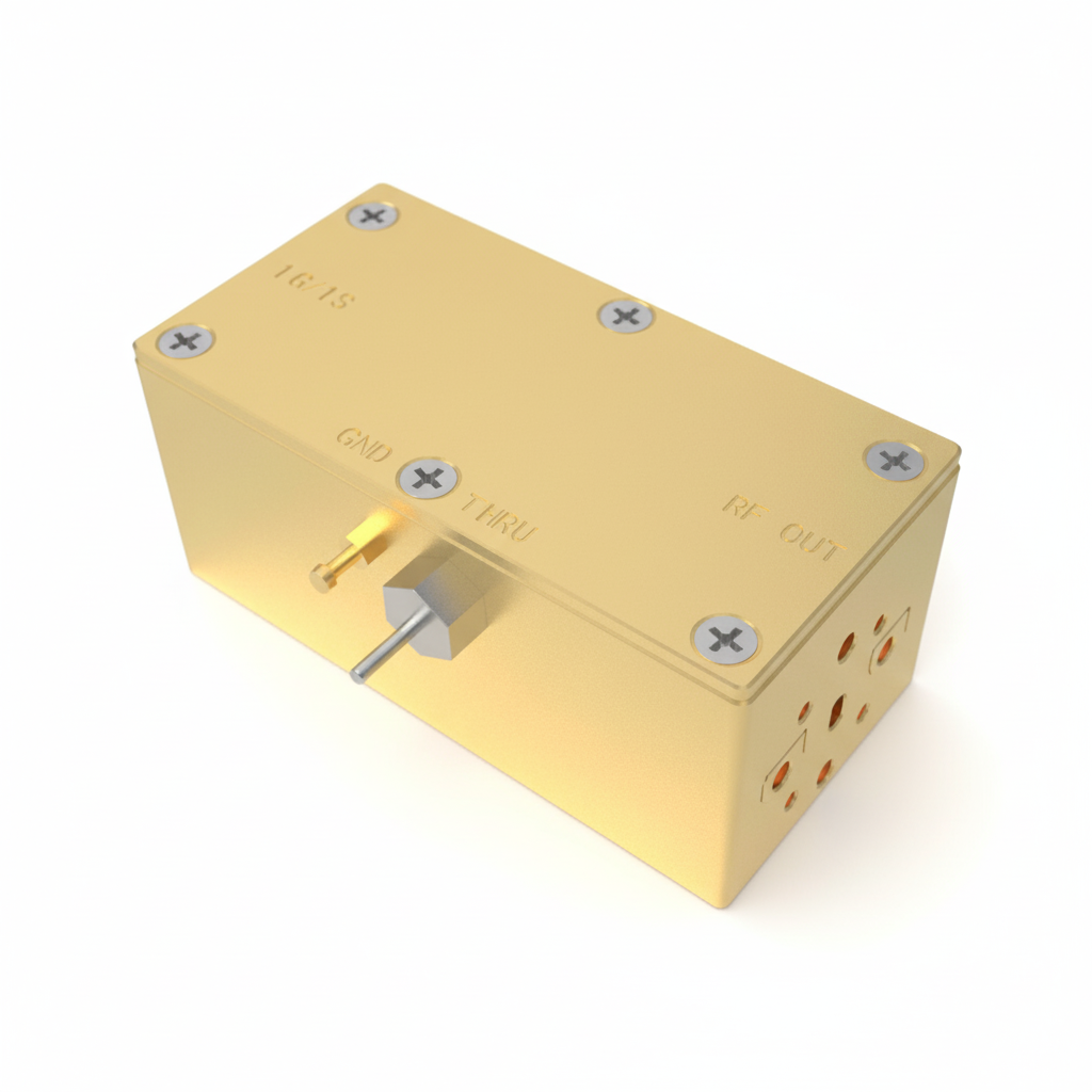
 Image 1 of 3
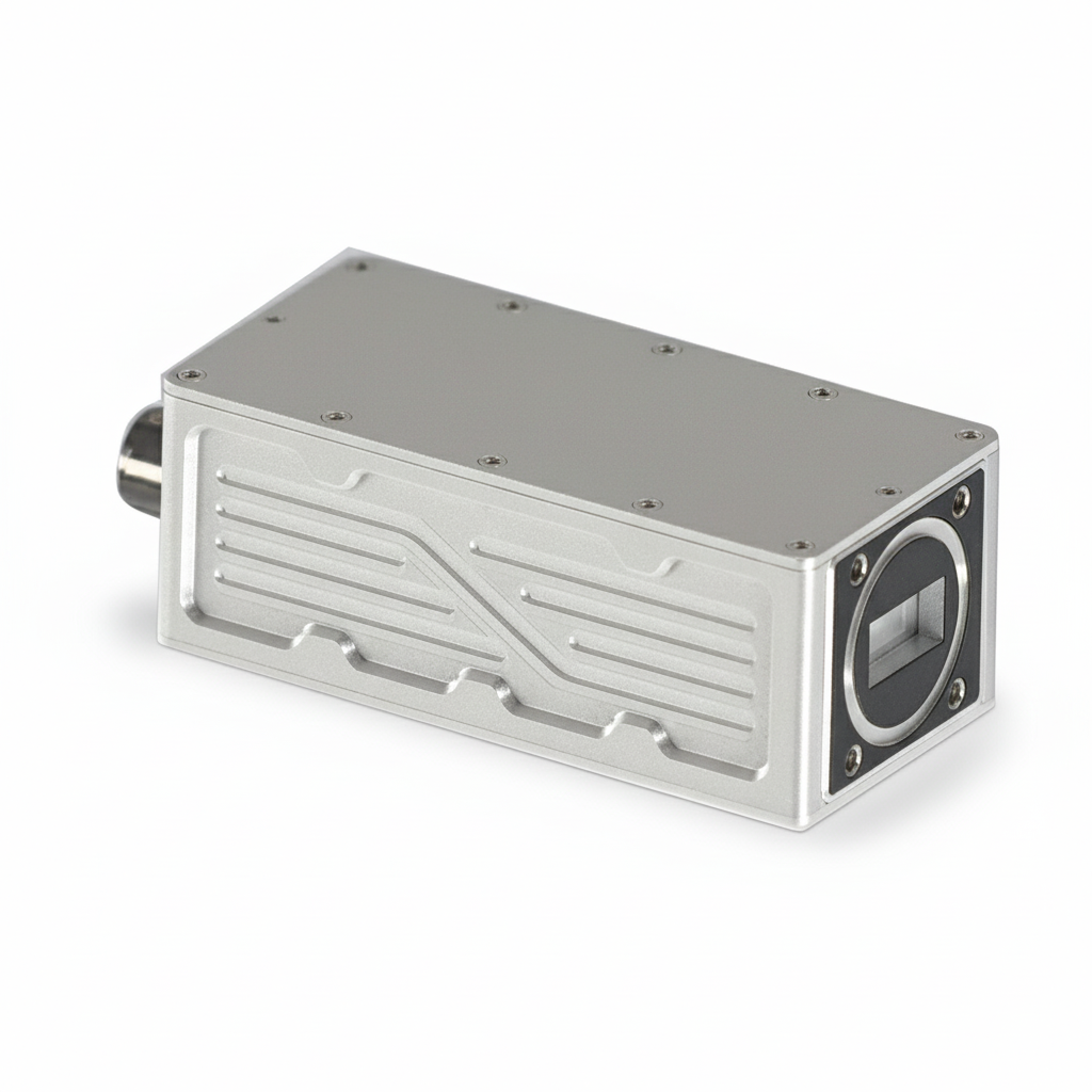
 Image 2 of 3
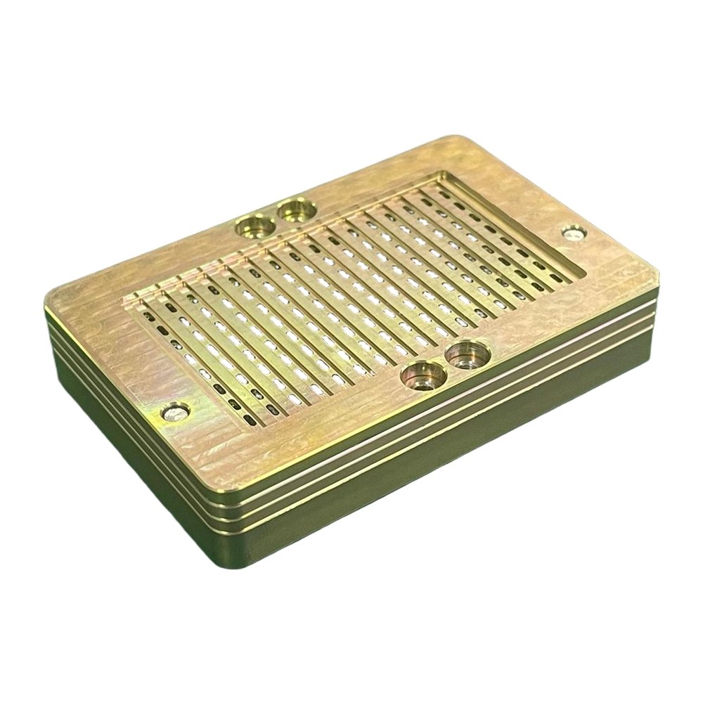
 Image 3 of 3
Electrical Specifications
| Parameter | Specification |
|---|---|
| Noise Figure (Room temperature @ 23°C) |
0.7 dB (typ.) / 0.8 dB (max.) – HQ 0.8 dB (typ.) / 0.9 dB (max.) – High Gain Low Noise 0.9 dB (typ.) / 1.0 dB (max.) – Universal |
| L.O. Stability |
±10 kHz / ±150 kHz / ±300 kHz (±1 ppm / ±10 ppm / ±30 ppm) |
| Phase Noise |
-70 dBc @ 1 kHz -80 dBc @ 10 kHz -90 dBc @ 100 kHz |
| Input VSWR | 2.5 : 1 (max.) |
| Output VSWR | 2.2 : 1 (max.) |
| Gain |
70 dB (max.), 55 dB (min.) – Universal 60 dB (min.) – High Gain Low Noise |
| Gain Flatness (Full Band) | ≤ 6 dB p-p |
| Output P1dB | +8 dBm (min.) |
| DC Power | +12 V to +24 V DC |
| Tone |
Frequency: 22 kHz ± 4 kHz Amplitude Voltage: 0.6 ± 0.2 V |
| Input (Waterproof) | WR-75 (Waveguide) |
| Output (Waterproof) |
F-Connector (75 Ω) N-Connector (50 Ω) |
| Operating Temperature | −30°C to +70°C |
FREQUENCY KU BAND
| Band | RF Frequency (GHz) | L.O. (GHz) | Output Frequency (MHz) |
|---|---|---|---|
| A | 10.70 – 11.70 | 9.75 | 950 – 1950 |
| B | 11.70 – 12.20 | 10.75 | 950 – 1450 |
| C | 12.20 – 12.75 | 11.25 | 950 – 1450 |
| D | 13.40 – 13.65 | 12.40 | 1000 – 1250 |
| E | 13.53 – 14.53 | 12.58 | 950 – 1950 |
| F | 13.75 – 14.50 | 12.80 | 950 – 1700 |
| G | 14.00 – 14.50 | 13.05 | 950 – 1450 |
| H | 10.70 – 12.75 | 10.25 | 450 – 2500 |
Dual Band
| Band | Sub Band | RF Frequency (GHz) | L.O. (GHz) | Output Frequency (MHz) | Voltage / Tone |
|---|---|---|---|---|---|
| A | Band 1 | 10.95 – 11.70 | 10.00 | 950 – 1700 | 13 V |
| Band 2 | 11.70 – 12.75 | 10.75 | 950 – 2000 | 18 V | |
| B | Band 1 | 10.70 – 11.70 | 9.75 | 950 – 1950 | 13 V |
| Band 2 | 11.70 – 12.75 | 10.75 | 950 – 2000 | 18 V | |
| C | Band 1 | 10.95 – 11.70 | 10.00 | 950 – 1700 | 13 V |
| Band 2 | 12.20 – 12.75 | 11.25 | 950 – 1500 | 18 V | |
| D | Band 1 | 10.70 – 11.70 | 9.75 | 950 – 1950 | 13 V |
| Band 2 | 11.70 – 12.75 | 10.60 | 1100 – 2150 | 18 V | |
| E | Band 1 | 10.70 – 12.75 | 10.40 | 300 – 2350 | 13 V |
| Band 2 | 13.75 – 14.50 | 12.80 | 950 – 1700 | 18 V | |
| F | Band 1 | 10.70 – 12.75 | 10.25 | 450 – 2500 | 13 V |
| Band 2 | 13.75 – 14.50 | 12.80 | 950 – 1700 | 18 V |
Triple Band
| Band | Sub Band | RF Frequency (GHz) | L.O. (GHz) | Output Frequency (MHz) | Voltage / Tone |
|---|---|---|---|---|---|
| A | Band 1 | 10.95 – 11.70 | 10.00 | 950 – 1700 | 13 V |
| Band 2 | 11.70 – 12.20 | 10.75 | 950 – 1450 | 13 V / 22 kHz | |
| Band 3 | 12.20 – 12.75 | 11.25 | 950 – 1500 | 18 V | |
| B | Band 1 | 10.95 – 11.70 | 10.00 | 950 – 1700 | 13 V |
| Band 2 | 11.70 – 12.25 | 10.75 | 950 – 1500 | 13 V / 22 kHz | |
| Band 3 | 12.25 – 12.75 | 11.30 | 950 – 1450 | 18 V | |
| C | Band 1 | 10.70 – 11.70 | 9.75 | 950 – 1950 | 13 V |
| Band 2 | 11.70 – 12.20 | 10.75 | 950 – 1450 | 13 V / 22 kHz | |
| Band 3 | 12.20 – 12.75 | 11.25 | 950 – 1500 | 18 V | |
| D | Band 1 | 10.70 – 11.70 | 9.75 | 950 – 1950 | 13 V |
| Band 2 | 11.70 – 12.25 | 10.75 | 950 – 1500 | 13 V / 22 kHz | |
| Band 3 | 12.25 – 12.75 | 11.30 | 950 – 1450 | 18 V | |
| E | Band 1 | 10.95 – 11.70 | 10.00 | 950 – 1700 | 13 V |
| Band 2 | 11.55 – 12.25 | 10.60 | 950 – 1650 | 13 V / 22 kHz | |
| Band 3 | 12.20 – 12.70 | 11.25 | 950 – 1450 | 18 V | |
| F | Band 1 | 10.70 – 11.80 | 9.75 | 950 – 2050 | 13 V |
| Band 2 | 10.95 – 12.10 | 10.00 | 950 – 2100 | 13 V / 22 kHz | |
| Band 3 | 11.70 – 12.75 | 10.75 | 950 – 2000 | 18 V | |
| G | Band 1 | 10.70 – 11.70 | 9.75 | 950 – 1950 | 13 V |
| Band 2 | 11.70 – 12.70 | 10.75 | 950 – 1950 | 13 V / 22 kHz | |
| Band 3 | 12.25 – 12.75 | 11.30 | 950 – 1450 | 18 V |
Quad Band
| Band | Sub Band | RF Frequency (GHz) | L.O. (GHz) | Output Frequency (MHz) | Voltage / Tone |
|---|---|---|---|---|---|
| A | Band 1 | 10.70 – 11.20 | 9.75 | 950 – 1450 | 13 V |
| Band 2 | 11.20 – 11.70 | 10.25 | 950 – 1450 | 13 V / 22 kHz | |
| Band 3 | 11.70 – 12.25 | 10.75 | 950 – 1500 | 18 V | |
| Band 4 | 12.25 – 12.75 | 11.30 | 950 – 1450 | 18 V / 22 kHz | |
| B | Band 1 | 10.70 – 10.95 | 9.75 | 950 – 1200 | 13 V |
| Band 2 | 10.95 – 11.70 | 10.00 | 950 – 1700 | 13 V / 22 kHz | |
| Band 3 | 11.70 – 12.25 | 10.75 | 950 – 1500 | 18 V | |
| Band 4 | 12.25 – 12.75 | 11.30 | 950 – 1450 | 18 V / 22 kHz | |
| C | Band 1 | 10.70 – 11.20 | 9.75 | 950 – 1450 | 13 V |
| Band 2 | 11.20 – 11.70 | 10.25 | 950 – 1450 | 13 V / 22 kHz | |
| Band 3 | 11.70 – 12.20 | 10.75 | 950 – 1450 | 18 V | |
| Band 4 | 12.20 – 12.75 | 11.25 | 950 – 1500 | 18 V / 22 kHz | |
| D | Band 1 | 10.95 – 11.45 | 10.00 | 950 – 1450 | 13 V |
| Band 2 | 11.45 – 11.95 | 10.50 | 950 – 1450 | 13 V / 22 kHz | |
| Band 3 | 11.70 – 12.20 | 10.75 | 950 – 1450 | 18 V | |
| Band 4 | 12.20 – 12.75 | 11.25 | 950 – 1500 | 18 V / 22 kHz |
FREQUENCY C BAND (ANTI-5G Guardband = 100MHz)
Single Band
| Band | RF Frequency (GHz) | L.O. (GHz) | Output Frequency (MHz) |
|---|---|---|---|
| A | 3.7 – 4.2 | 5.15 | 950 – 1450 |
| B | 3.8 – 4.2 | 5.15 | 950 – 1350 |
| C | 3.9 – 4.2 | 5.15 | 950 – 1250 |
| D | 4.0 – 4.2 | 5.15 | 950 – 1150 |
| E | 4.5 – 4.8 | 5.75 | 950 – 1250 |
| F | 4.5 – 4.8 | 5.95 | 1150 – 1450 |
| G | 4.0 – 4.8 | 5.75 | 950 – 1750 |
| H | 3.7 – 4.8 | 5.75 | 950 – 2050 |
Dual Band
| Band | Sub Band | RF Frequency (GHz) | L.O. (GHz) | Output Frequency (MHz) | Voltage / Tone |
|---|---|---|---|---|---|
| A | Band 1 | 3.7 – 4.2 | 5.15 | 950 – 1450 | 13 V |
| Band 2 | 4.5 – 4.8 | 5.75 | 950 – 1250 | 18 V | |
| B | Band 1 | 3.8 – 4.2 | 5.15 | 950 – 1450 | 13 V |
| Band 2 | 4.5 – 4.8 | 5.75 | 950 – 1250 | 18 V | |
| C | Band 1 | 3.9 – 4.2 | 5.15 | 950 – 1450 | 13 V |
| Band 2 | 4.5 – 4.8 | 5.75 | 950 – 1250 | 18 V | |
| D | Band 1 | 4.0 – 4.2 | 5.15 | 950 – 1450 | 13 V |
| Band 2 | 4.5 – 4.8 | 5.75 | 950 – 1250 | 18 V |