W‑Band Coupler (75 GHz – 110 GHz)
Product Features
High frequency, ultra-wide bandwidth
High coupling, high flatness
Low loss, high power handling
Operating temperature: -55℃~85℃
Overview
Frequency range: 75 GHz to 110 GHz (W‑band)
Function: Directional coupler for power splitting, sampling, monitoring, and signal injection in millimeter‑wave systems
Applications: Radar (automotive and short‑range imaging), millimeter‑wave communication links, test & measurement, phased arrays, beamforming networks, and research & development
Key Specifications (typical)
Frequency band: 75–110 GHz
Coupling values: available options typically from 3 dB (equal split) up to 30 dB; common choices: 3.0, 6.0, 10.0, 20.0 dB
Isolation: ≥ 18 dB (commonly 20–30 dB depending on design & frequency)
Return loss (port match): ≥ 15 dB across band (typical 18–25 dB)
Insertion loss (through path): minimal excess loss, typically 0.3–1.5 dB depending on coupling and construction
Directivity: ≥ 15 dB (typical 20–30 dB)
Power handling: depends on size and cooling; small-signal designs handle several watts CW; larger waveguide implementations handle higher power
Phase balance: typically ±3° to ±10° across band depending on design
Amplitude balance: typically ±0.2 to ±1.0 dB across band
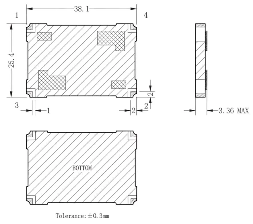
Mechanical & Interface Options
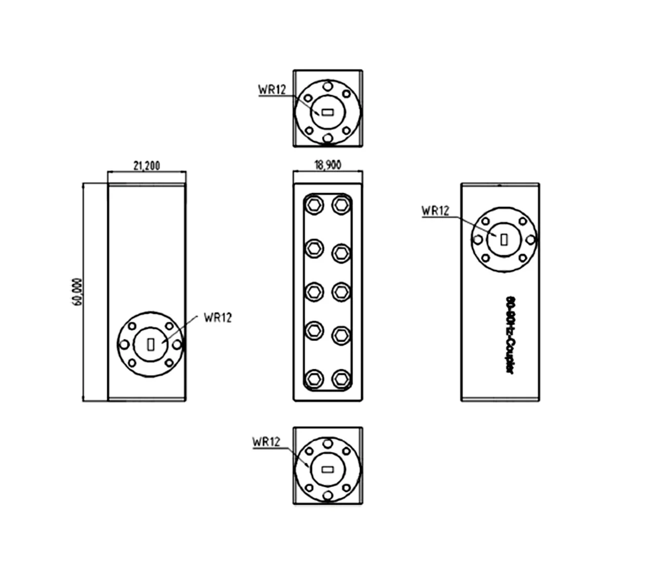
Waveguide types: WR‑10 (2.54 mm × 1.27 mm internal dimensions) is the standard W‑band rectangular waveguide interface
Flanges: UG‑387/U or custom precision flanges; flange finish and alignment pins for repeatable mating
Connector zed options: 1.0 mm or 1.85 mm coaxial transitions for connector zed test applications
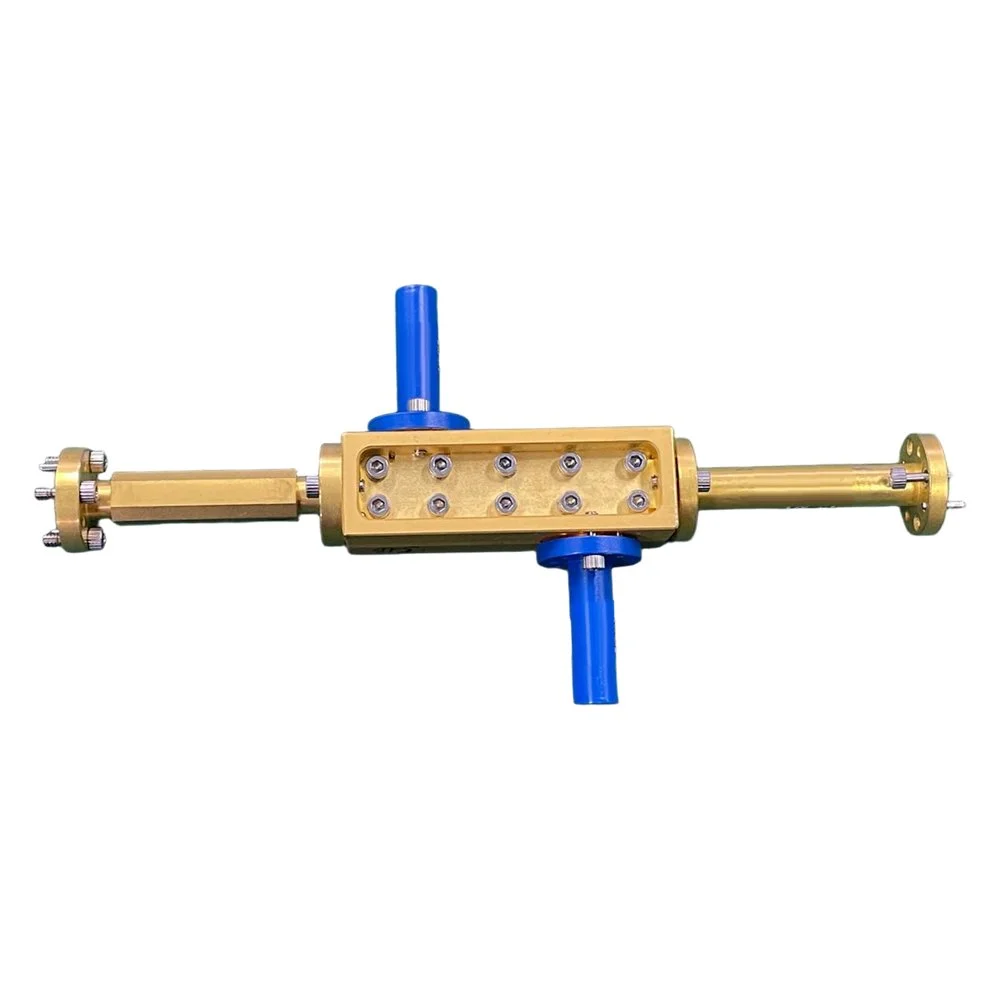
Housing: machined metal (aluminum, brass, or stainless) with precision internal geometries; surface treatments and plating available for environmental resilience
Size and weight: compact millimeter‑wave modules suitable for integration into arrays and test fixtures
Design Types
Waveguide branch-line coupler: excellent power handling, low loss, high directivity; preferred for high‑performance systems
Lange/parallel strapline coupler: compact printed circuit option for integration with planar circuitry; may require careful fabrication for W‑band tolerances
Rat‑race and hybrid ring variants: used for specific phasing and combining/splitting tasks
Directional couplers with multi‑octave compensation networks: engineered to maintain coupling flatness across 75–110 GHz
Performance Considerations
Bandwidth: achieving flat coupling and high directivity across the entire 75–110 GHz band requires precision geometry and tight manufacturing tolerances
Fabrication tolerance: micron‑level dimensional control is often necessary; plating thickness and surface roughness significantly affect loss at W‑band
Thermal stability: thermal expansion can shift center frequencies and degrade matching; mechanical design should account for operating temperature range
Integration: transitions between waveguide and planar circuits must be optimized to minimize reflections and insertion loss
Testing & calibration: vector network analyzer measurements with on‑wafer or waveguide calibration kits are standard to verify S‑parameters and directivity
Typical Use Cases
Active and passive millimeter‑wave test setups: sample a small portion of power for monitoring or measurement without disrupting the main link
Phased array beamforming networks: distribute equal or unequal power to sub‑arrays with controlled phase and amplitude balance
Calibration and diagnostic ports: monitor transmitter output, detect faults, and enable closed‑loop control
Radio astronomy and sensing: low‑loss sampling of high‑frequency signals in receiver chains
Ordering & Customization Options
Standard catalog couplers in common coupling values and flange types
Custom coupling level, directivity, and mechanical interface per system requirements
Environmental ruggedization: conformal coating, hermetic sealing, and vibration‑hardened mounting
Integrated transitions: waveguide‑to‑coax or waveguide‑to‑substrate integrated for plug‑and‑play integration
Screening and testing: performance guaranteed with S‑parameter data, lot traceability, and optional extended temperature testing
Summary W‑band couplers covering 75–110 GHz enable precise splitting and sampling of millimeter‑wave signals for high‑performance radar, communications, and measurement systems. Selecting the right coupler requires balancing coupling value, directivity, insertion loss, and mechanical interface while accounting for tight fabrication tolerances and thermal effects. Customization options make these components adaptable to demanding system architectures and integration constraints.

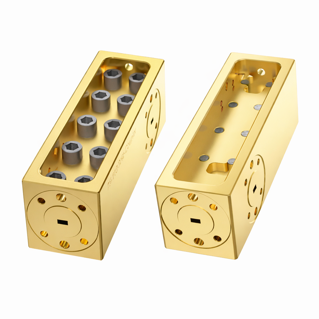 Image 1 of 4
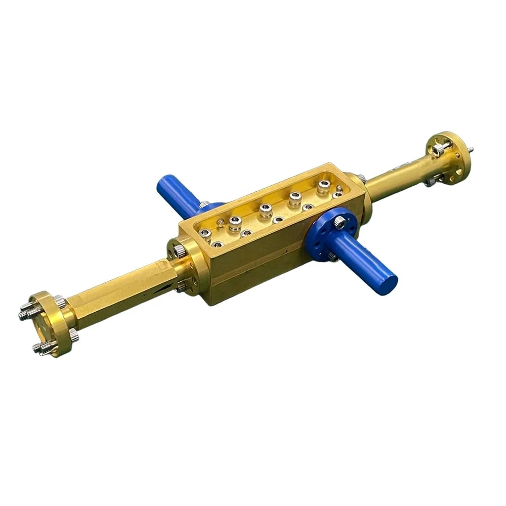 Image 2 of 4
 Image 3 of 4
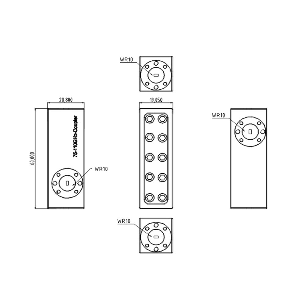 Image 4 of 4