Wavelength and dimensions: free‑space wavelength ~3.2 mm at 94 GHz. Radiating elements, feed structures, and lens/aperture sizes scale to millimeter dimensions; tolerances are tight.
Materials: low‑loss dielectrics and high‑conductivity metals are essential to minimize insertion and surface losses. Common substrates include alumina, quartz, and specific low‑loss RF laminates designed for mmWave use.
Feeding and transitions: waveguide (WR‑10 for 75–110 GHz, though some designs use custom WR‑10 variants), microstrip, CPW, or stripline with careful transition design to avoid mismatch and radiation losses. Probe and aperture transitions must be optimized.
Antenna types:
Horn antennas (rectangular or conical): good gain, simple pattern, useful for measurement and lab setups.
Waveguide slot arrays: high gain and efficiency, rugged for outdoor or airborne use.
Microstrip or patch arrays: compact, planar form factor, scalable to phased arrays but require loss management and accurate phase control.
Lens antennas (silicon or Teflon lenses): enable high gain with compact apertures, often used with feed arrays.
Phased arrays: beam steering, MIMO and adaptive beamforming for dynamic scanning and clutter rejection.
Beamwidth and gain: small apertures still achieve moderate-to-high gain due to short wavelength. Aperture efficiency and surface/assembly tolerances impact realized gain.
Polarization: linear (vertical/horizontal) or circular as required by system link budget and polarization discrimination needs.

 Image 1 of 3
 Image 2 of 3
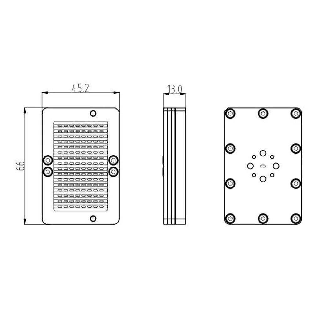 Image 3 of 3