Overview A Ku‑Band 25W BUC (Block Upconverter) is a compact, high‑efficiency RF transmitter used in satellite ground terminals to convert L‑band IF (typically 950–2150 MHz) up to Ku‑band transmit frequencies (approximately 13.75–14.5 GHz for outbound FSS/SNG or other Ku allocations) and amplify the signal to a 25 watt (≈44 dBm) RF output power level. This module is engineered for VSAT, flyaway, maritime and portable satellite systems where size, weight, and power efficiency matter.
Output power: 25 W (typical), specified in dBm and watts for clear link planning.
Frequency range: Ku‑band transmit range (specific coverage depends on model; common ranges cover 13.75–14.50 GHz).
IF input: 950–2150 MHz L‑band (single or dual L‑band ports depending on model).
Modulation support: Compatible with common satellite modulations (QPSK, 8PSK, 16APSK, DVB‑S2/S2X, etc.) when paired with suitable modem.
Phase noise: Low phase noise oscillator for improved EIRP stability and spectral purity.
Output linearity: High linearity for multicarrier and high‑order modulation; typical ACLR/IMD specs provided by manufacturer.
Gain: High and stable gain with adjustable IF/LO gain control.
LO options: Built‑in OCXO or Rubidium reference, or external 10 MHz reference input.
Interfaces: IF +24 dBmV to +10 dBmV typical ranges, RF monitor port, alarm and control via Ethernet, RS‑232/RS‑485, or Ethernet SNMP.
Power: DC power input range (e.g., 24–48 VDC) with power‑save and low power modes for portable applications.
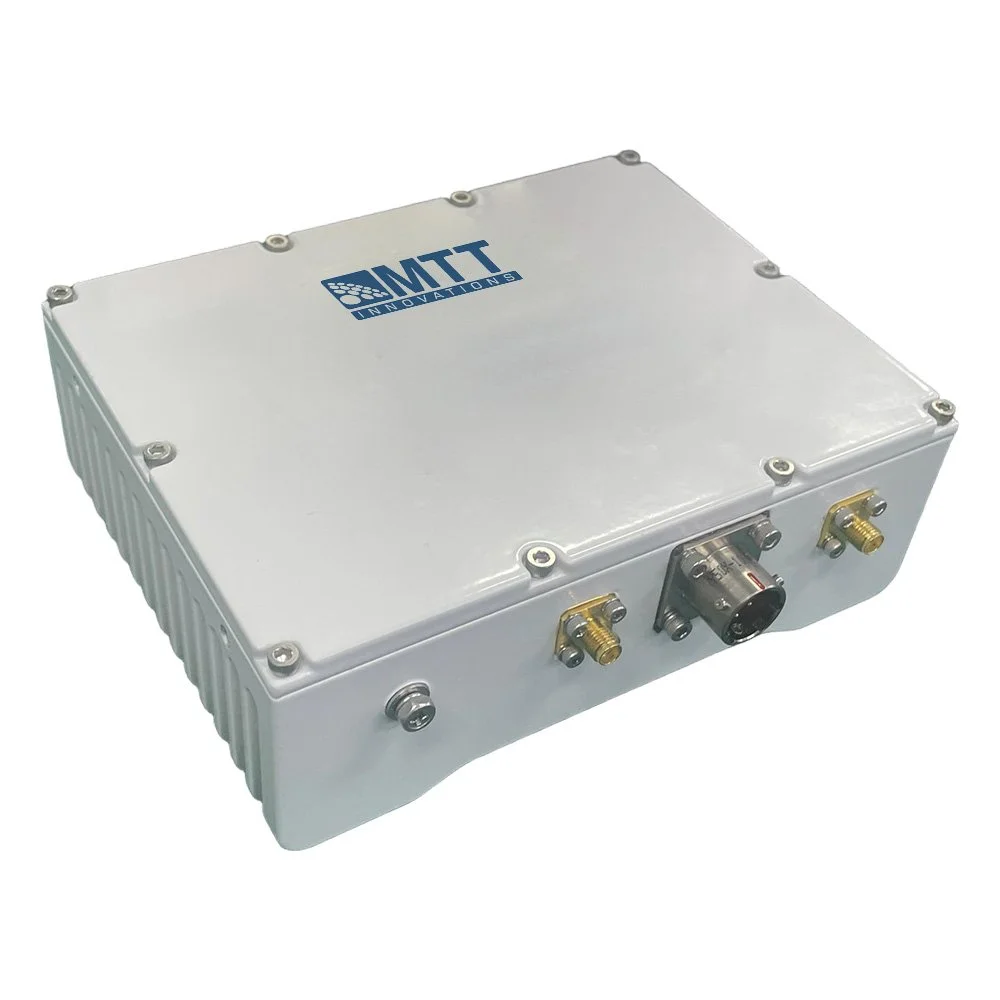
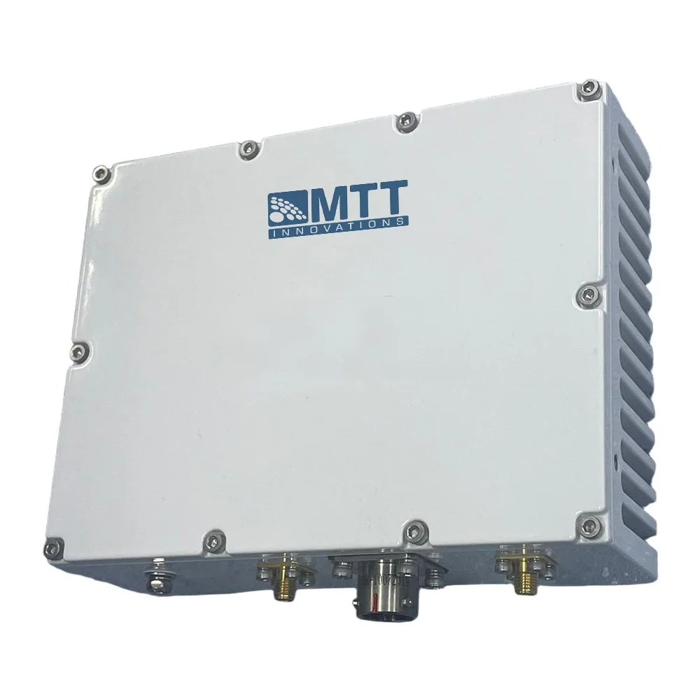
Mechanical: Ruggedized housing, heat‑sink or forced‑air cooled, available in 1U/2U rack or compact flyaway form factors.
Environmental: MIL‑STD or commercial variants rated for shock, vibration, salt fog, and wide temperature operation (typical −30°C to +55°C operating).
EIRP: System EIRP depends on BUC output power plus antenna gain. A 25 W BUC on a 1.2–1.8 m antenna typically supports reliable links for many VSAT and SNG applications.
Link budgeting: When designing links, include BUC output power, antenna G/T, path loss, uplink margin, rain fade, and required Eb/No for chosen modulation and coding.
Linear vs. saturated operation: For single carrier, saturated operation increases apparent power but degrades modulation fidelity. For multi‑carrier or high‑order modulation use the BUC in its linear region with appropriate back‑off.
Phase noise and stability: Critical for high‑order modulations and carrier aggregation. Choose BUC models with disciplined LO (OCXO/Rb or external ref) for frequency stability.
Cooling and duty cycle: Ensure adequate ventilation for continuous 25 W operation; forced cooling may be required in high ambient temperatures or compact enclosures.

 Image 1 of 2
 Image 2 of 2