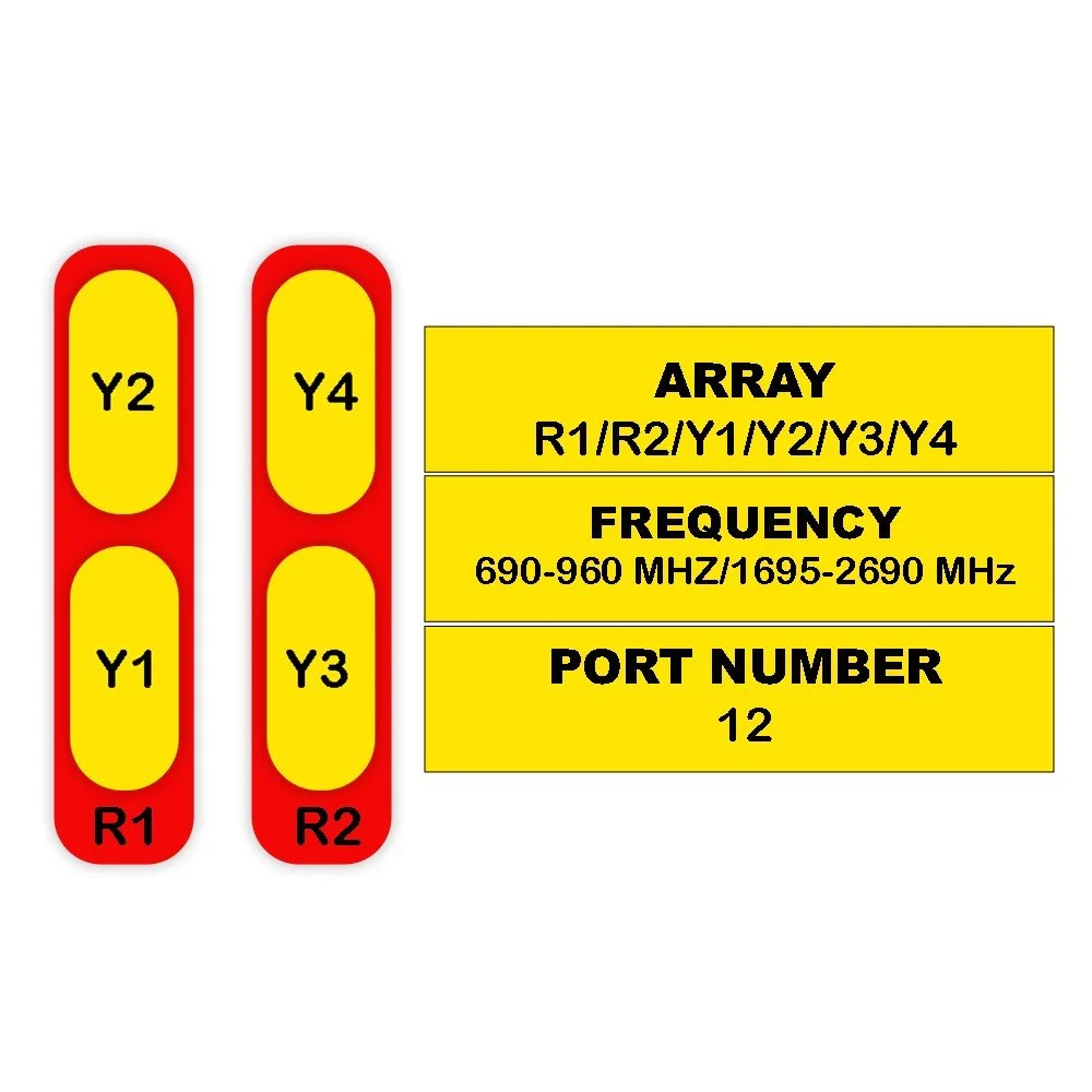
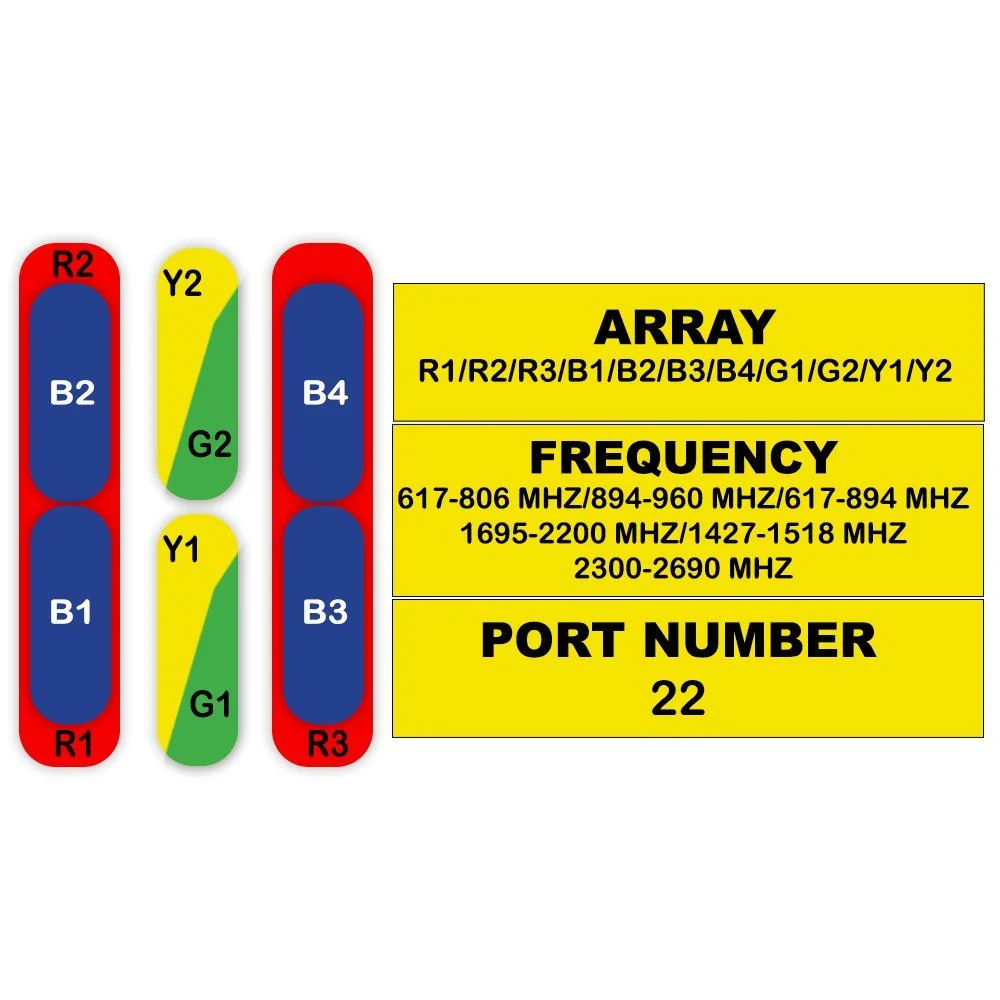
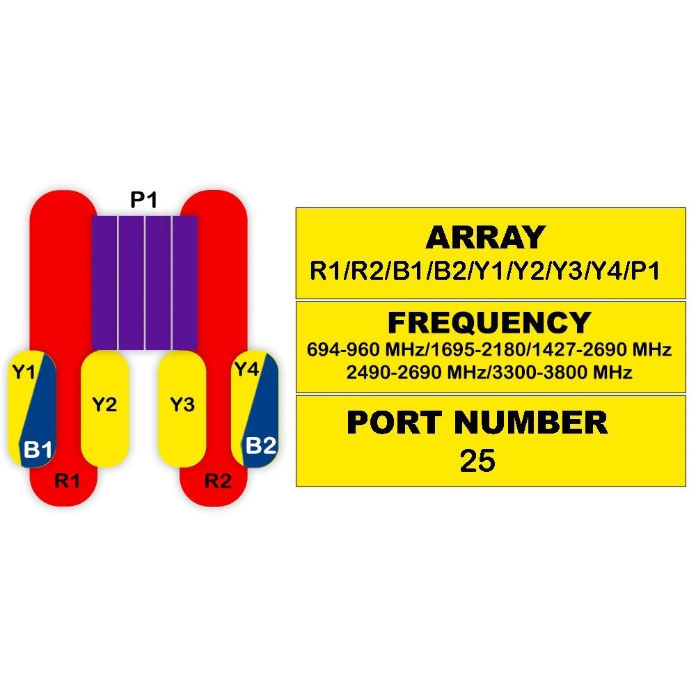
Frequency range: 698–2690 MHz (Full 700/850/900/1700/1800/1900/2100/2300/2500/2600 bands)
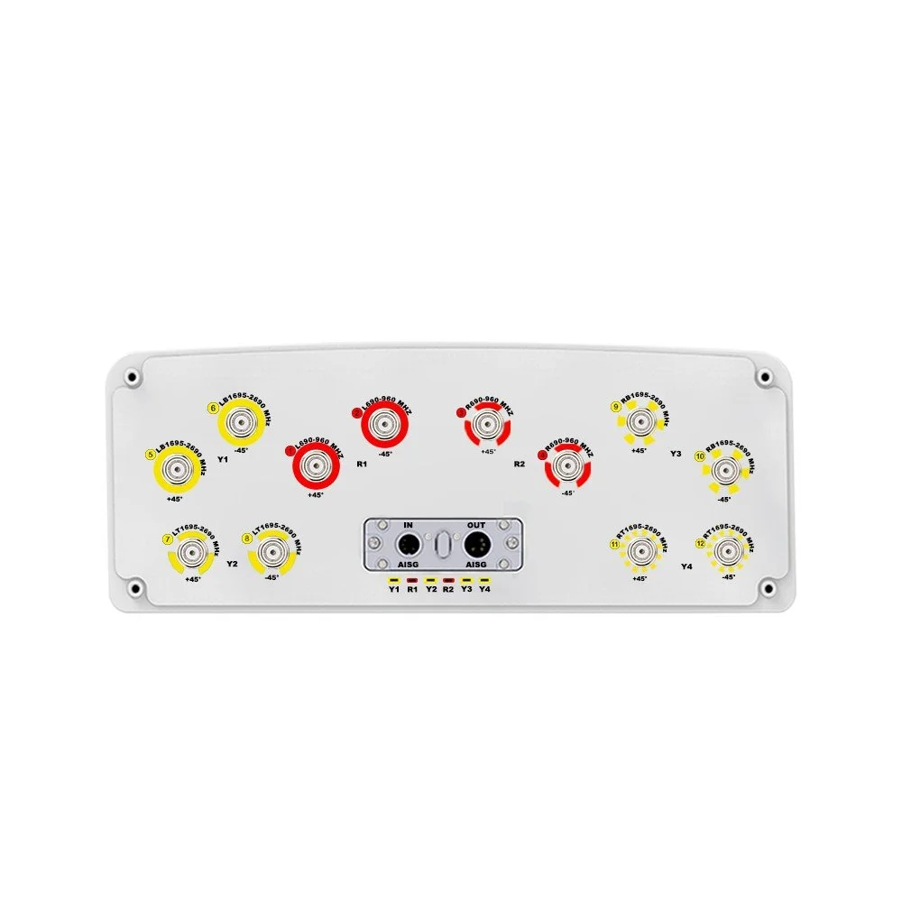
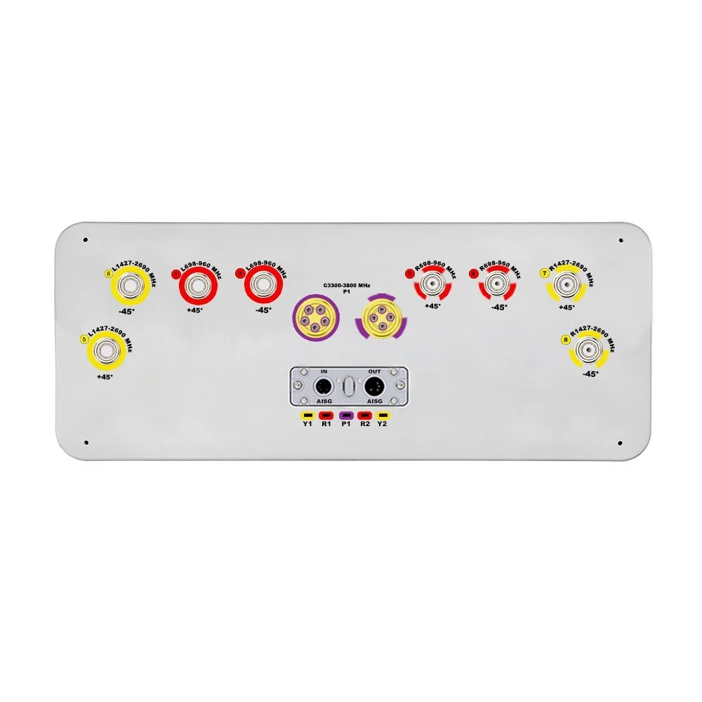
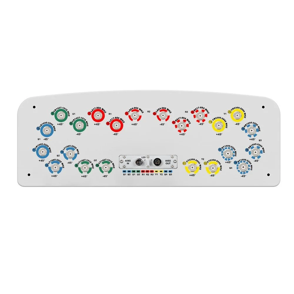
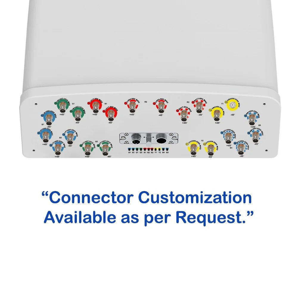
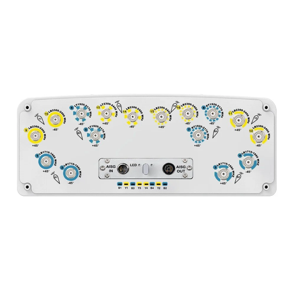
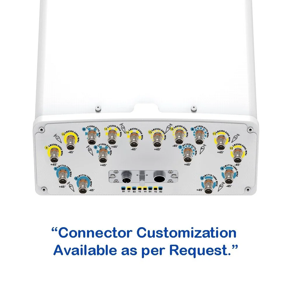
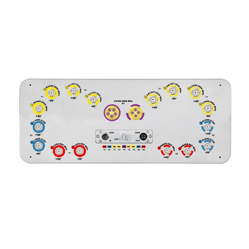
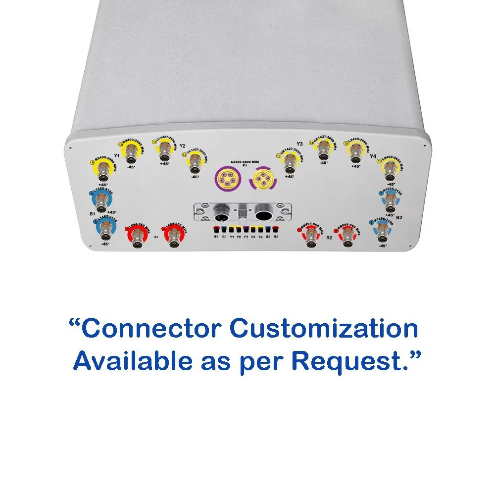
12 RF ports: supports multiple operators, MIMO layers, or mixed-sector configurations from a single mechanical unit
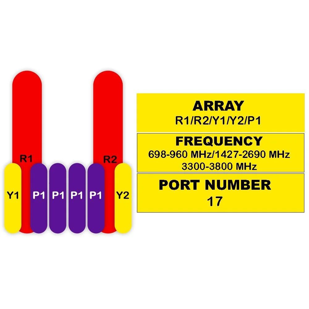
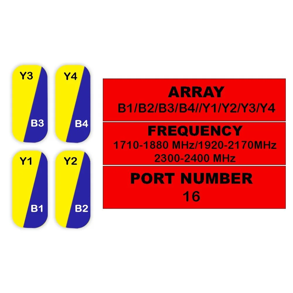
Hybrid split-beam architecture: independent electrical tilts and patterns across sub-arrays for optimized coverage and interference control
High port-to-port isolation: minimizes inter-port coupling, enabling denser spectrum reuse and co-located carriers
Low passive intermodulation (PIM) construction: factory-tested to meet strict carrier PIM requirements for high-power deployments
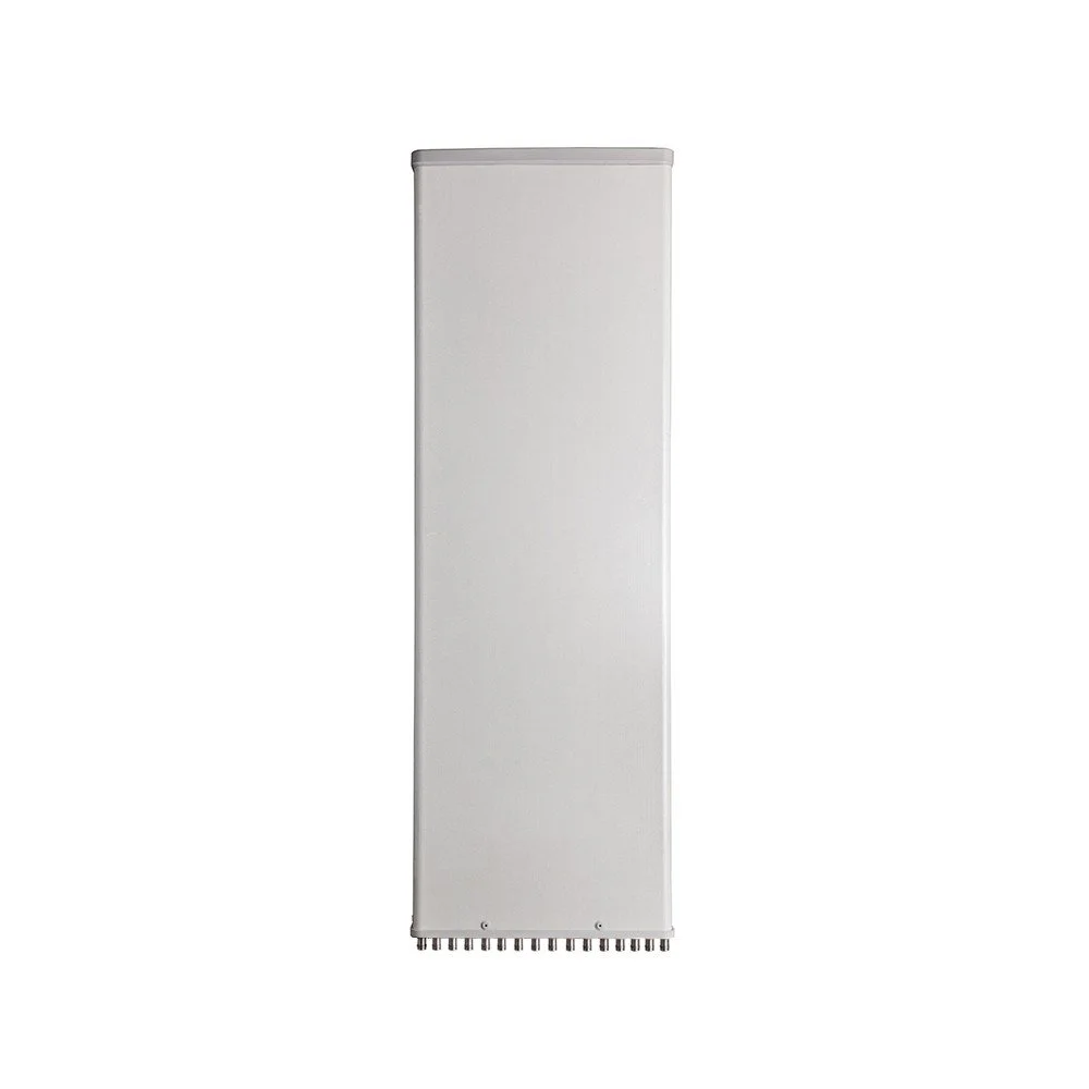
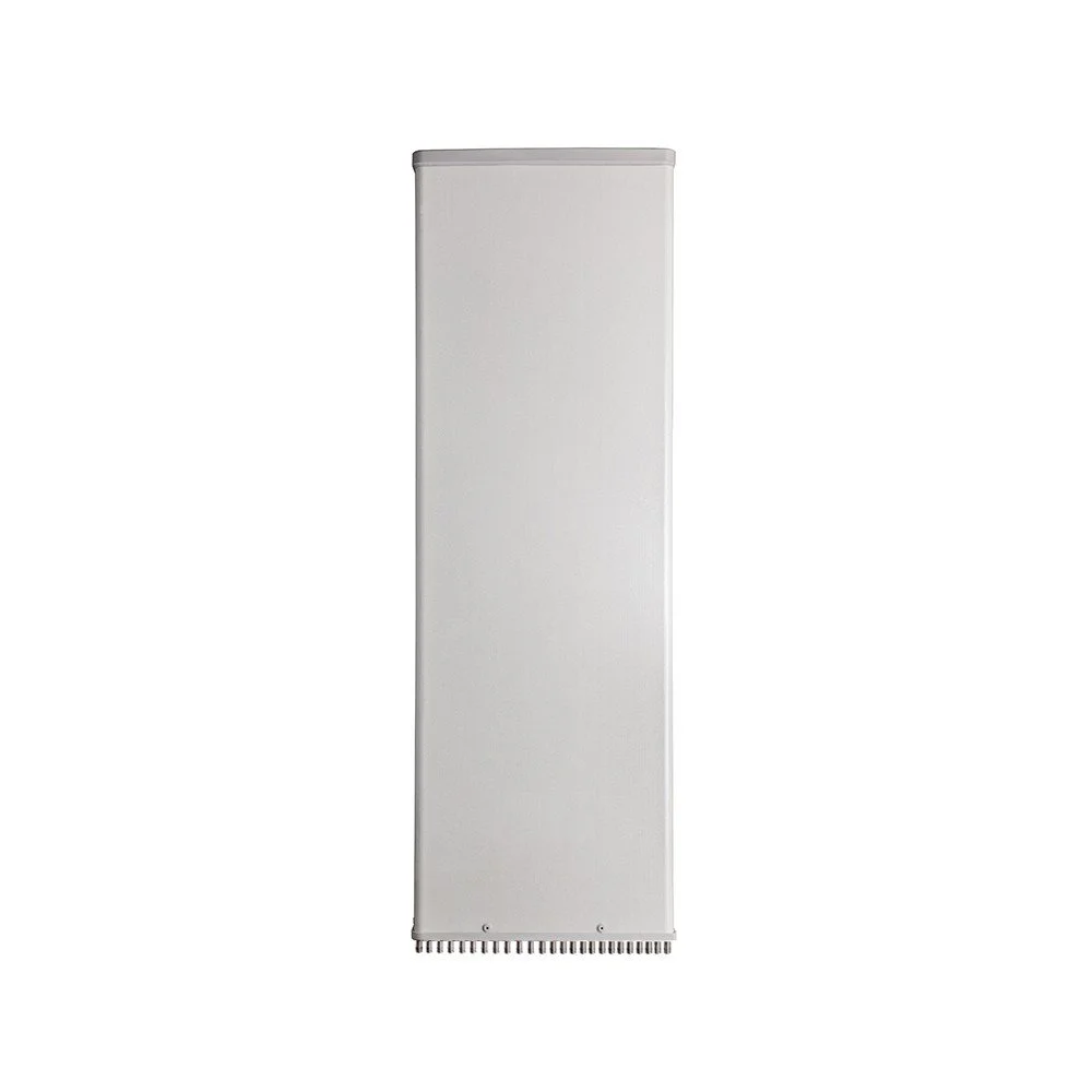
Ruggedized radome and corrosion-resistant hardware: built for long-term outdoor exposure in coastal and industrial environments
Wide horizontal beamwidth options: supports tight sectorization and flexible cell planning
Multiple electrical downtilt settings: remote tilt compatibility via tilt-controlled ports or integrated mechanical tilt options
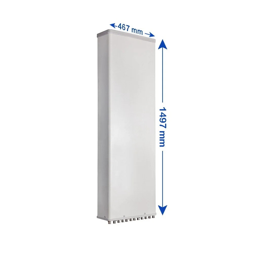
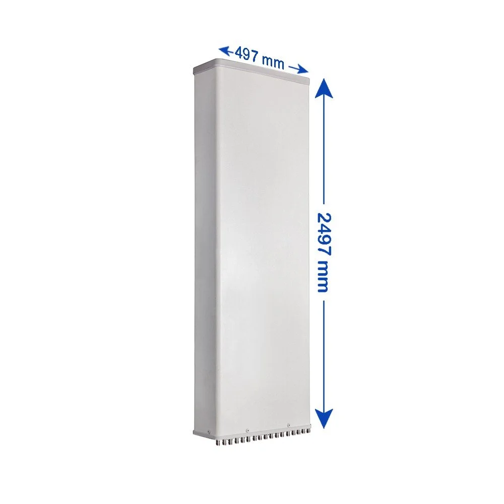
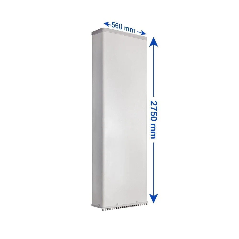
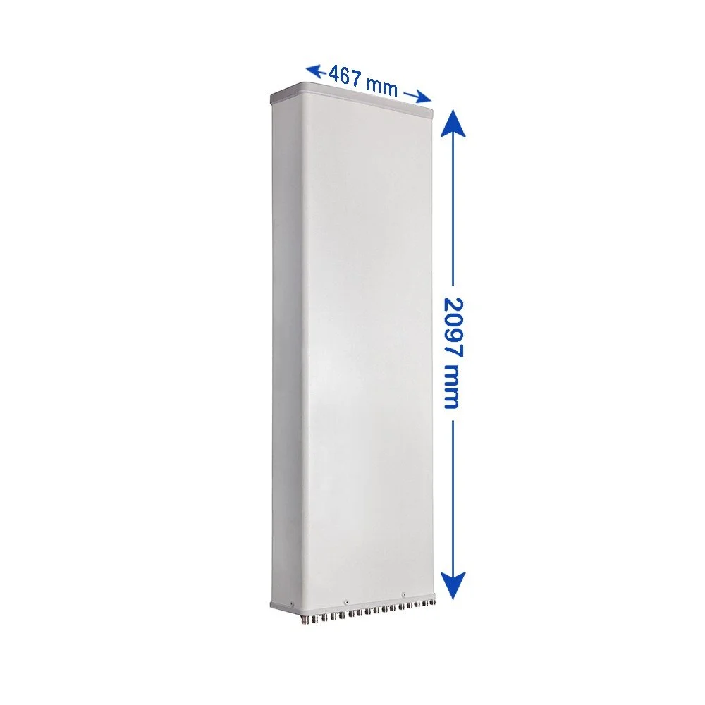
Compact footprint with integrated mounting: reduces wind load and tower space; straightforward pole or pipe mount kits included
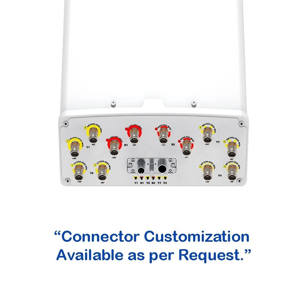
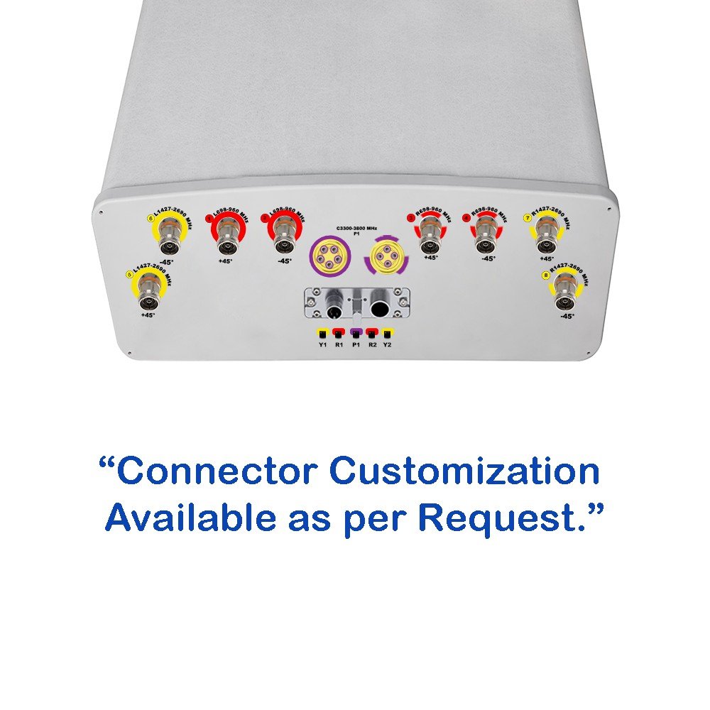
Easy cable management: labeled, weatherproof connectors for rapid installation and maintenance
Compliant with industry standards: meets environmental, RF safety, and mechanical requirements for commercial cellular deployment

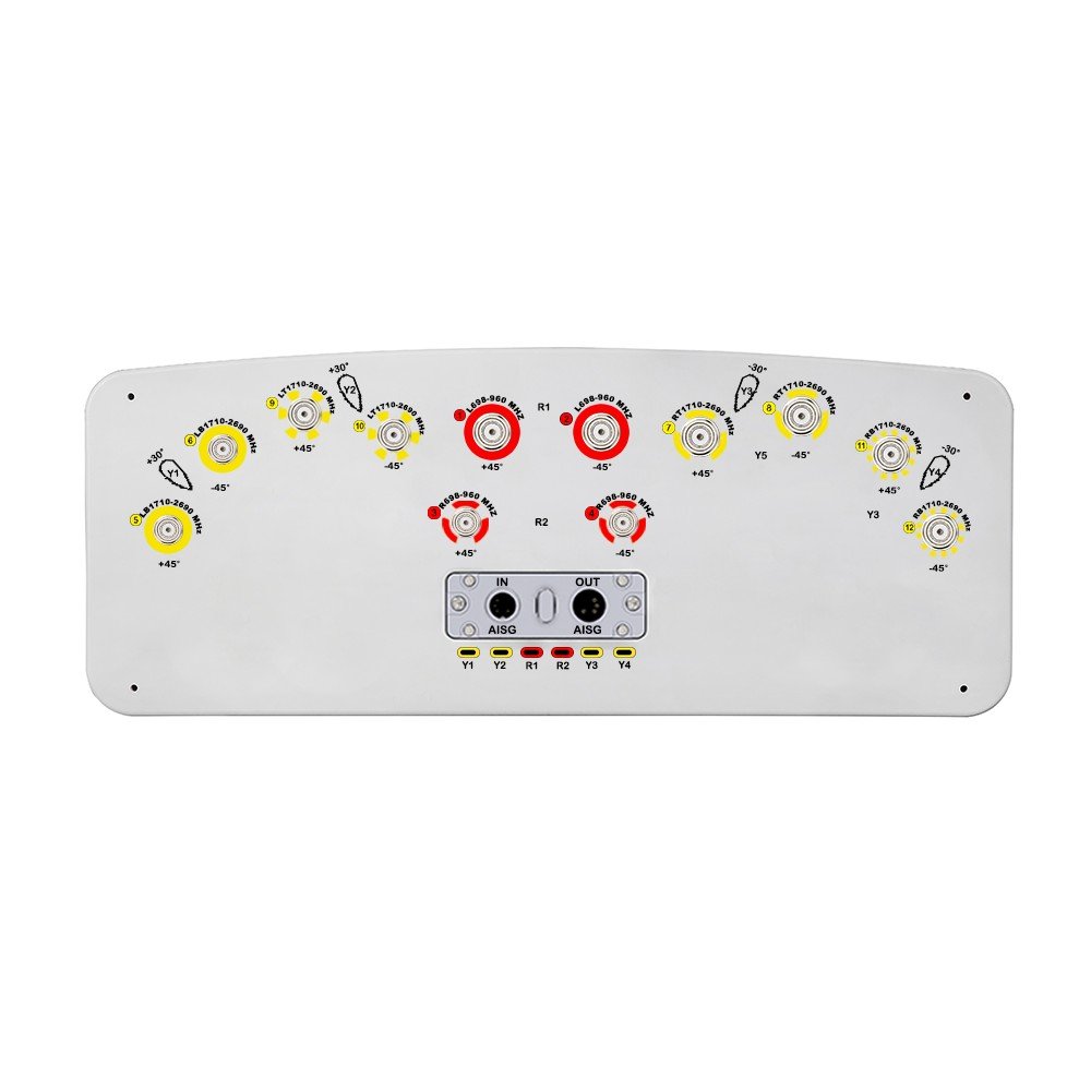 Image 1 of 6
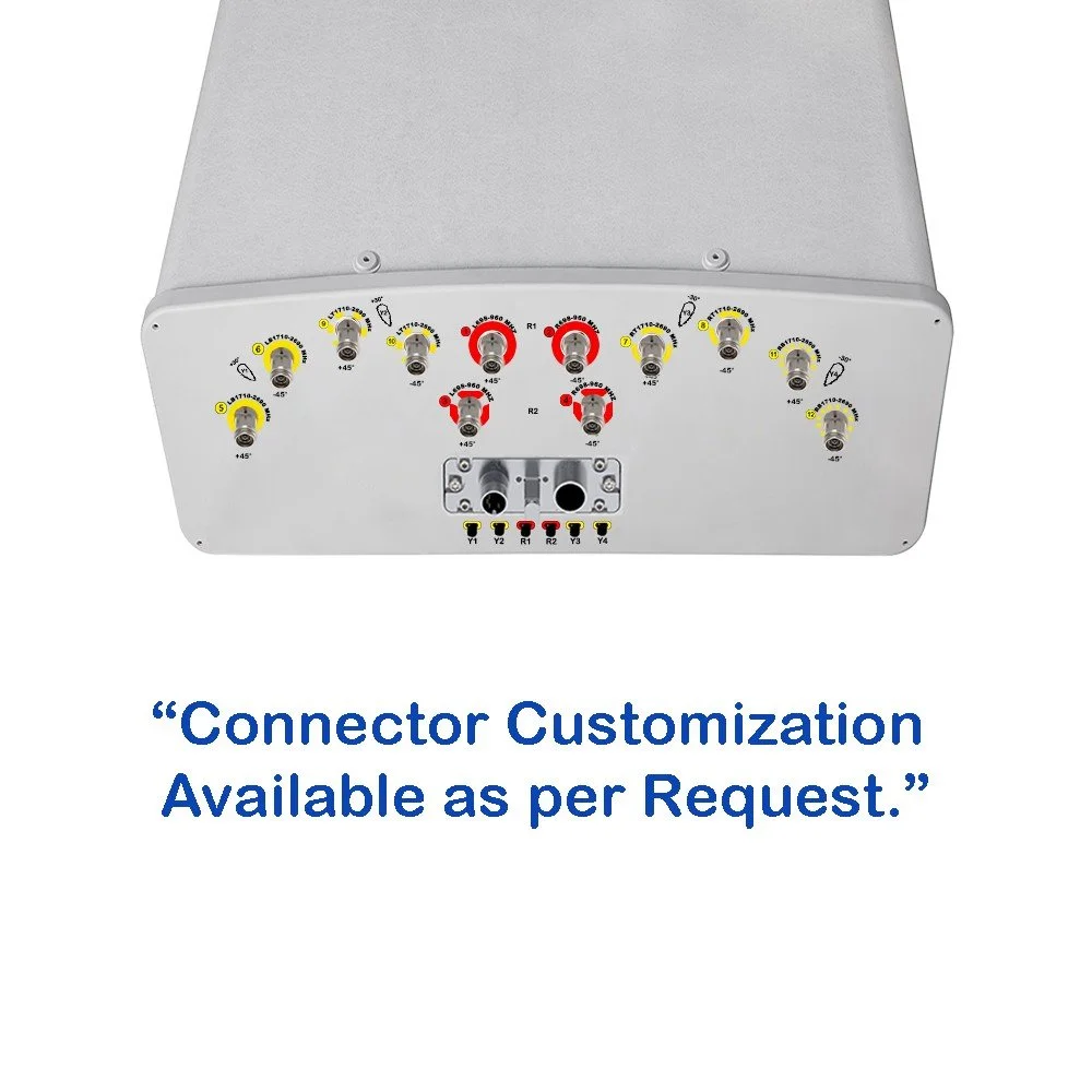 Image 2 of 6
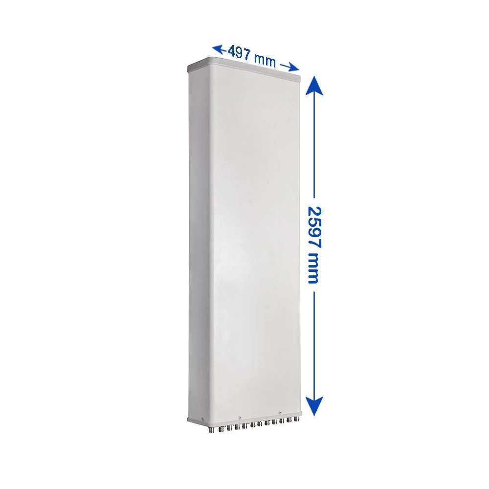 Image 3 of 6
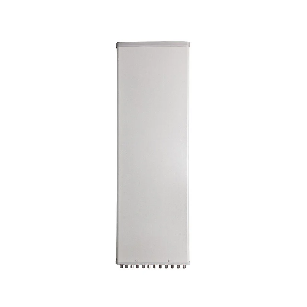 Image 4 of 6
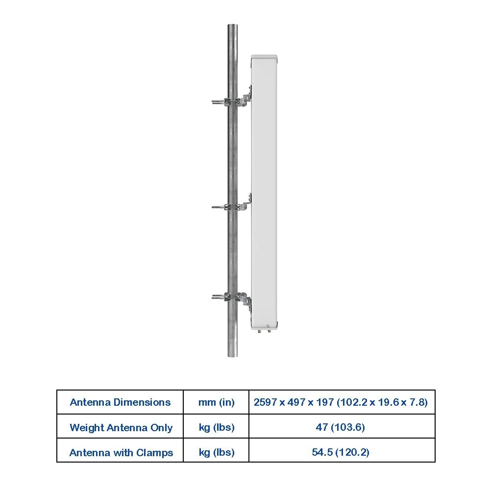 Image 5 of 6
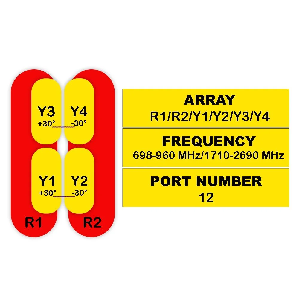 Image 6 of 6