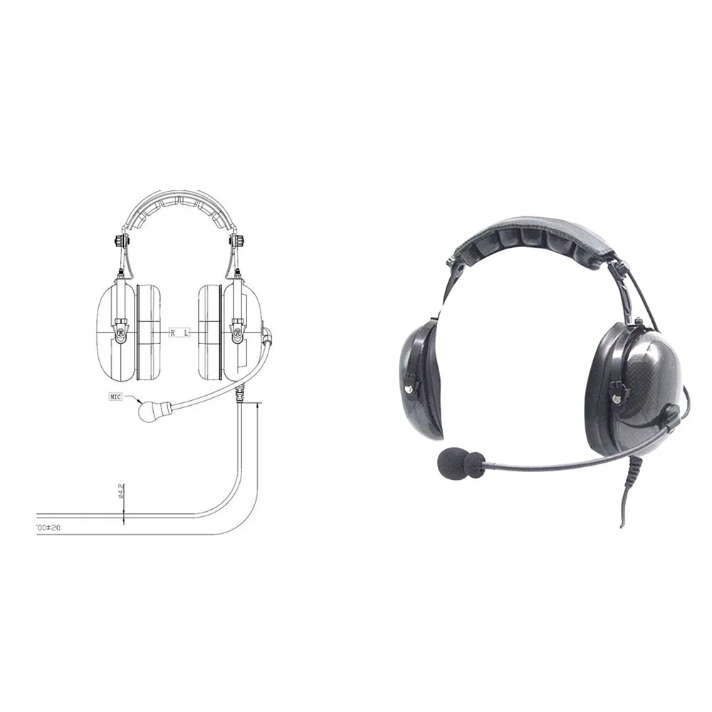
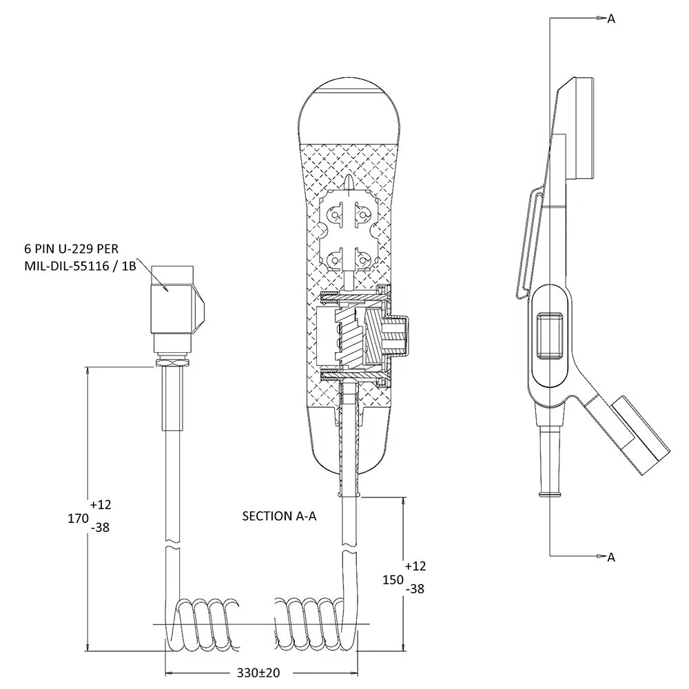
 Image 1 of 3
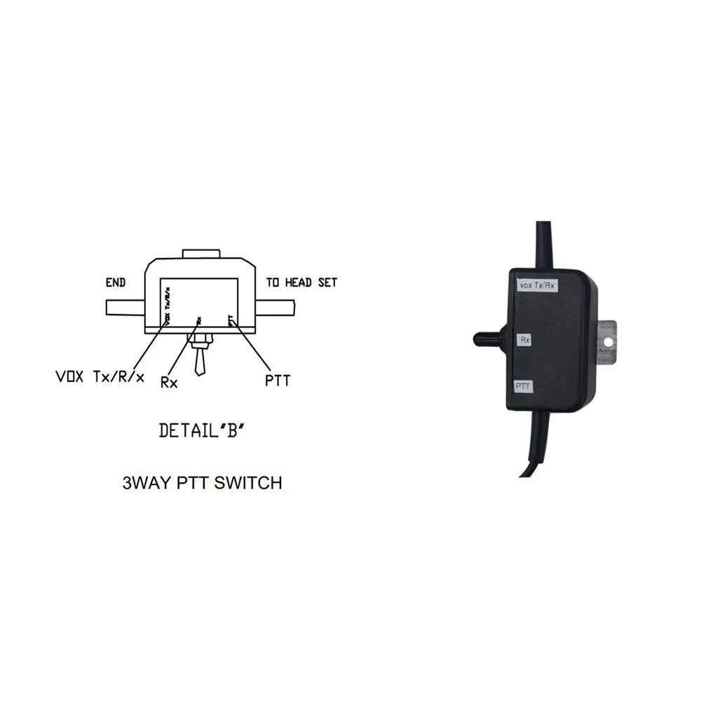
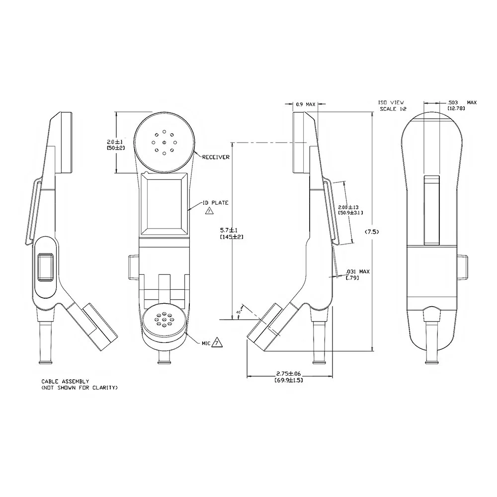
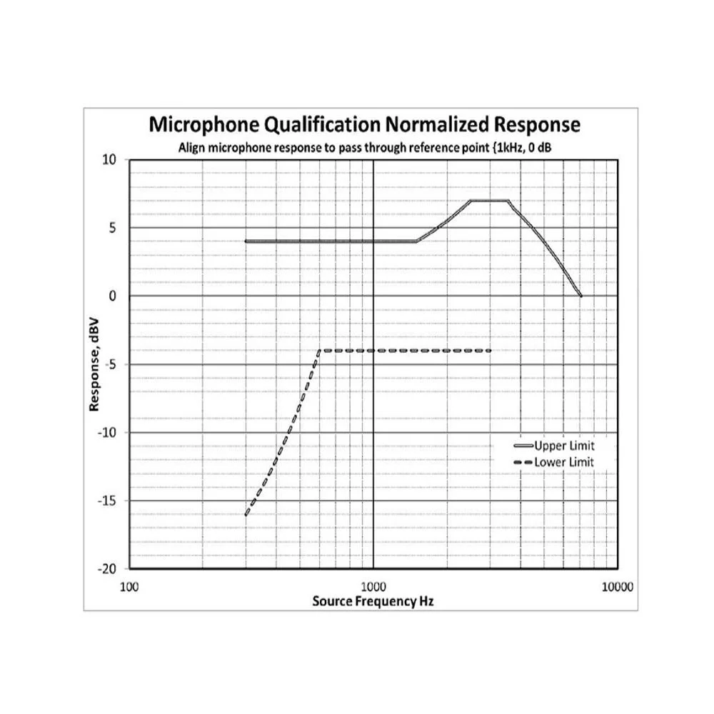 Image 2 of 3
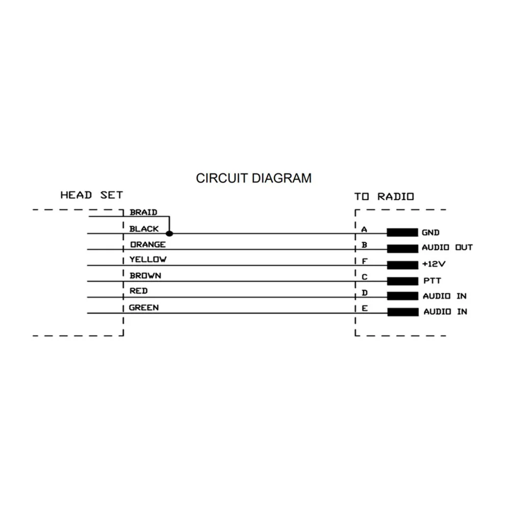
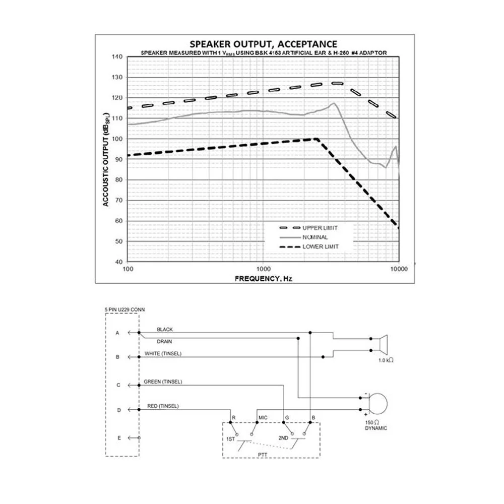 Image 3 of 3
| Functional / Feature | Specifications |
|---|---|
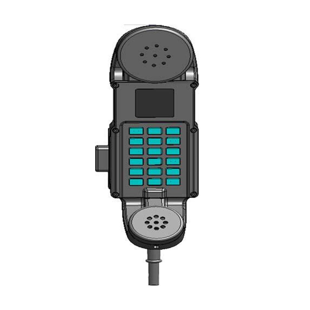
| Keypad Controls |
|
| Power On/Off Operation |
|
| Display |
|
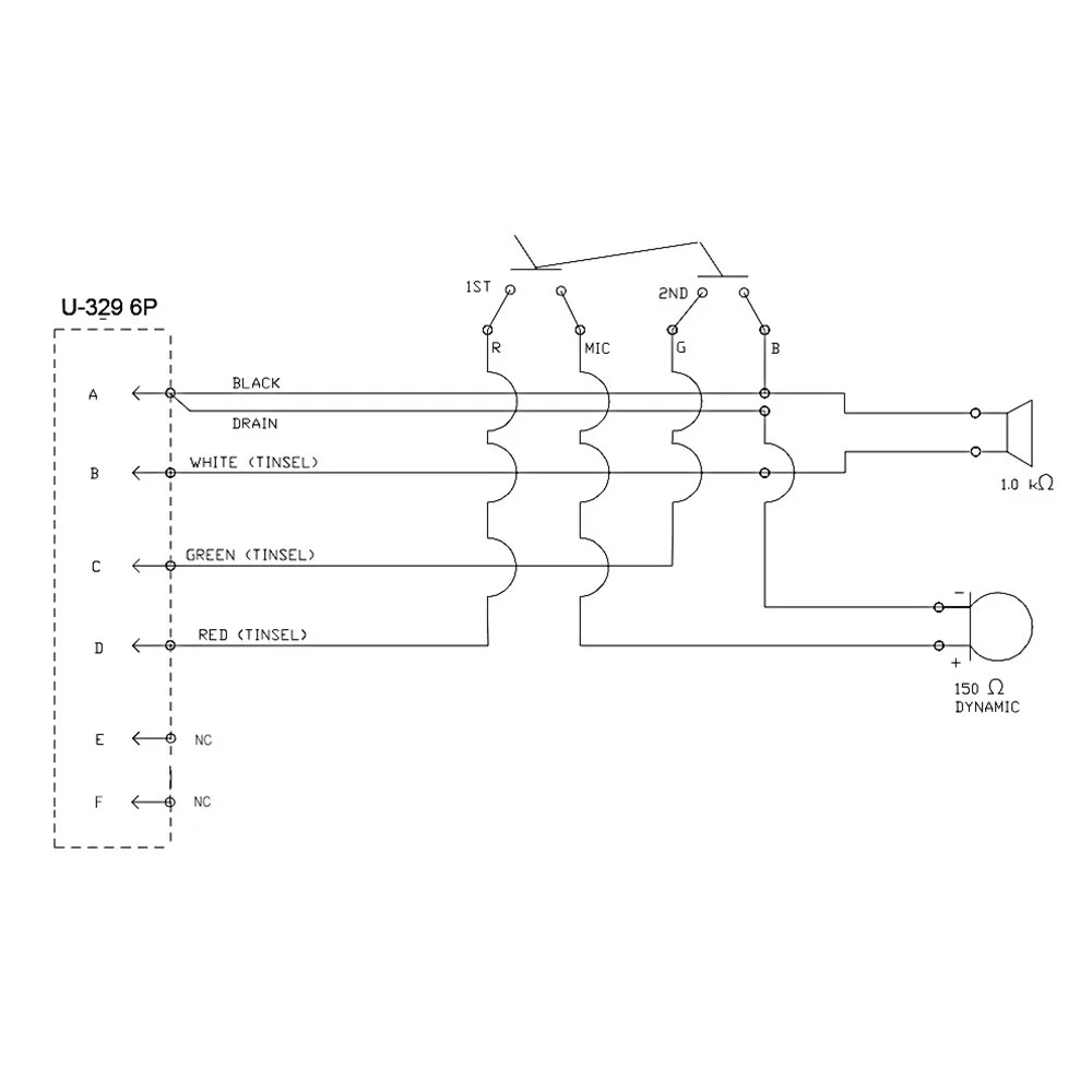
| PTT Switch | Push To Talk |
| Power Source | 5V nominal (negative ground) |
| Current Consumption | 200mA Max |
| Radio On/Off Switch | Radio ON/OFF switch used to remotely control the radio |
| Connector / Cable (DHS to Radio) |
|
| ELECTRICAL SPECIFICATIONS | |||||
|---|---|---|---|---|---|
| PARAMETERS | UNITS | MIN | TYP | MAX | |
| MICROPHONE SPECIFICATIONS | |||||
| ELEMENT TYPE | DYNAMIC | ||||
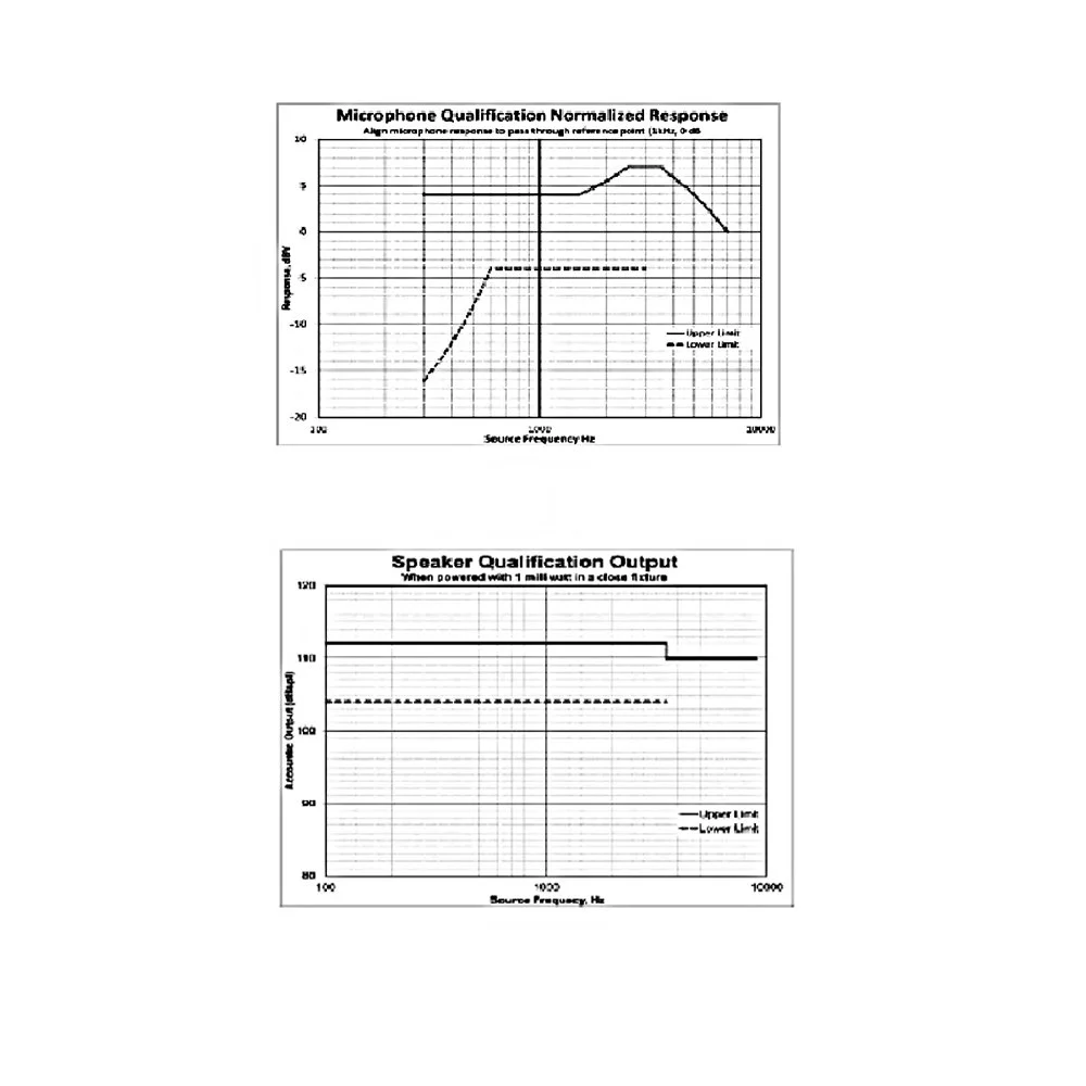
| FREQUENCY RESPONSE | Hz | 300 | 3500 | ||
| TEST CONDITIONS (PER 3QA000306) | |||||
| REFERENCE | 0 dBV = 1 Vrms/Pa | ||||
| BIAS RESISTOR, Rb | Ω | N/A | |||
| TEST SOURCE | MOUTH SIMULATOR, B&K 4227 | ||||
| TEST DISTANCE | 0.25" FROM LIP RING | ||||
| INPUT LEVEL | dBSPL | 94 | |||
| MICROPHONE PERFORMANCE | |||||
| DC RESISTANCE | Ω | 128 | 150 | 173 | |
| IMPEDANCE @ 1000 Hz | Ω | 135 | 159 | 183 | |
| SENSITIVITY @ 300 Hz | dBV | -78.7 | -74.7 | -70.7 | |
| SENSITIVITY @ 1000 Hz | dBV | -72.5 | -68.5 | -64.5 | |
| SENSITIVITY @ 3000 Hz | dBV | -66.2 | -62.2 | -58.2 | |
| DISTORTION (THD) 300 - 3500 Hz | % | 5.0 | |||
| MICROPHONE PERFORMANCE (ORIGINAL) | |||||
| TEST CONDITIONS | |||||
| BIAS RESISTOR, Rb | Ω | N/A | |||
| TEST SOURCE | MOUTH SIMULATOR, B&K 4227 | ||||
| TEST DISTANCE | 0.25" FROM LIP RING | ||||
| INPUT LEVEL | dBSPL | 103 dBSPL (28 DYNES/CM2) | |||
| SENSITIVITY @ 1000 Hz | dBm | -56.0 | |||
| SPEAKER SPECIFICATIONS | |||||
|---|---|---|---|---|---|
| TEST CONDITIONS (PER 3QA000305) | |||||
| ACQUISITION TRANSDUCER | B&K 4153, ARTIFICIAL EAR | ||||
| ACOUSTIC COUPLER | H-250 #4 ADAPTOR | ||||
| INPUT LEVEL | Vrms | 1.000 | |||
| SPEAKER PERFORMANCE | |||||
| DC RESISTANCE | Ω | 850 | 1000 | 1150 | |
| IMPEDANCE @ 1000 Hz | Ω | 876 | 1031 | 1185 | |
| OUTPUT LEVEL @ 300 Hz | dBSPL | 96 | 108 | 120 | |
| OUTPUT LEVEL @ 1000 Hz | dBSPL | 98 | 110 | 122 | |
| OUTPUT LEVEL @ 2000 Hz | dBSPL | 100 | 112 | 124 | |
| FREQUENCY RANGE | Hz | 100 | 3500 | ||
| RATED INPUT POWER (CONTINUOUS) | WATT | 0.30 | |||
| DISTORTION (THD) | % | 10 | |||
| LOAD TEST | 1,000 Hz SINE WAVE, 0.30 W INPUT, 8 HOUR DURATION RESPONSE SHALL BE WITHIN 3 dB OF INITIAL | ||||
| PTT SWITCH | |||||
| CYCLE LIFE | CYCLES | 2,000,000 | |||
| RATING @ 12 VDC | mA | 50 | |||
| MECHANICAL SPECIFICATIONS | |||||
| MASS | lbm | 2 | |||
| CABLE PULL FROM HANDSET, AXIAL | lbf | 40 | |||
| CABLE PULL FROM CONNECTOR, AXIAL | lbf | 25 | 40 | ||
| CABLE FLEX AT HANDSET (2 lbm WT.) | CYCLES | 25,000 | |||
| CABLE ELONGATION (3:1) | CYCLES | 15,000 | |||
| ENVIRONMENTAL SPECIFICATIONS | |||||
| OPERATING TEMP. | F [°C] | -40 [-40] | 149 [65] | ||
| STORAGE TEMP. | F [°C] | -67 [-55] | 158 [70] | ||
| THERMAL SHOCK | 2 HRS @ -40 / 2 HRS @ +158, SIX CYCLES, 24 HRS TOTAL | ||||
| HUMIDITY | METHOD 507.5, PROCEDURE I, CYCLIC HIGH, B2 FOR 6 CYCLES, FOLLOWED BY A 24 HR DRY OUT | ||||
| ALTITUDE | 50 Kft FOR 2 HOURS, FOLLOWED IMMEDIATELY BY 2 HRS @ 10 Kft. | ||||
| IMMERSION | 1 METER FOR 2 HRS (24 HOUR RECOVER ALLOWABLE) | ||||
| VIBRATION | MIL-STD-202, METHOD 201; 2 HRS IN EACH OF 3 PLANES | ||||