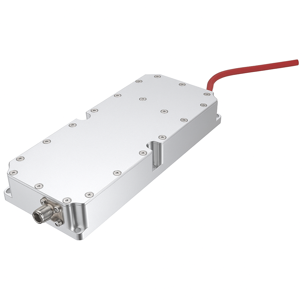
 Image 1 of 6
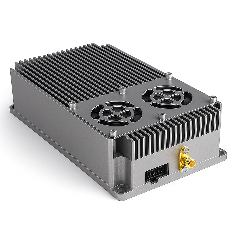
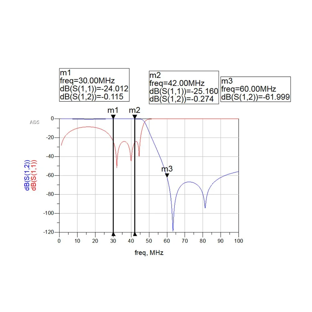 Image 2 of 6
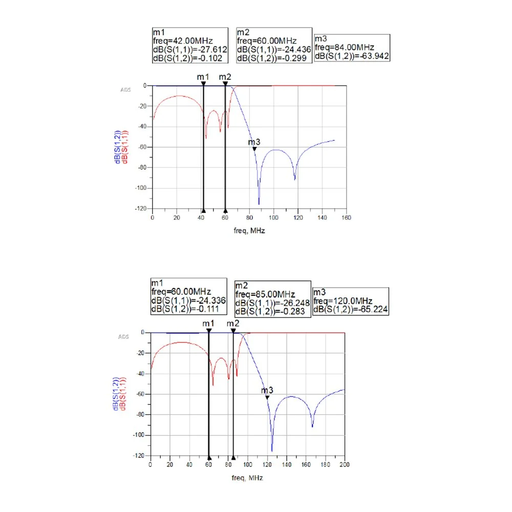 Image 3 of 6
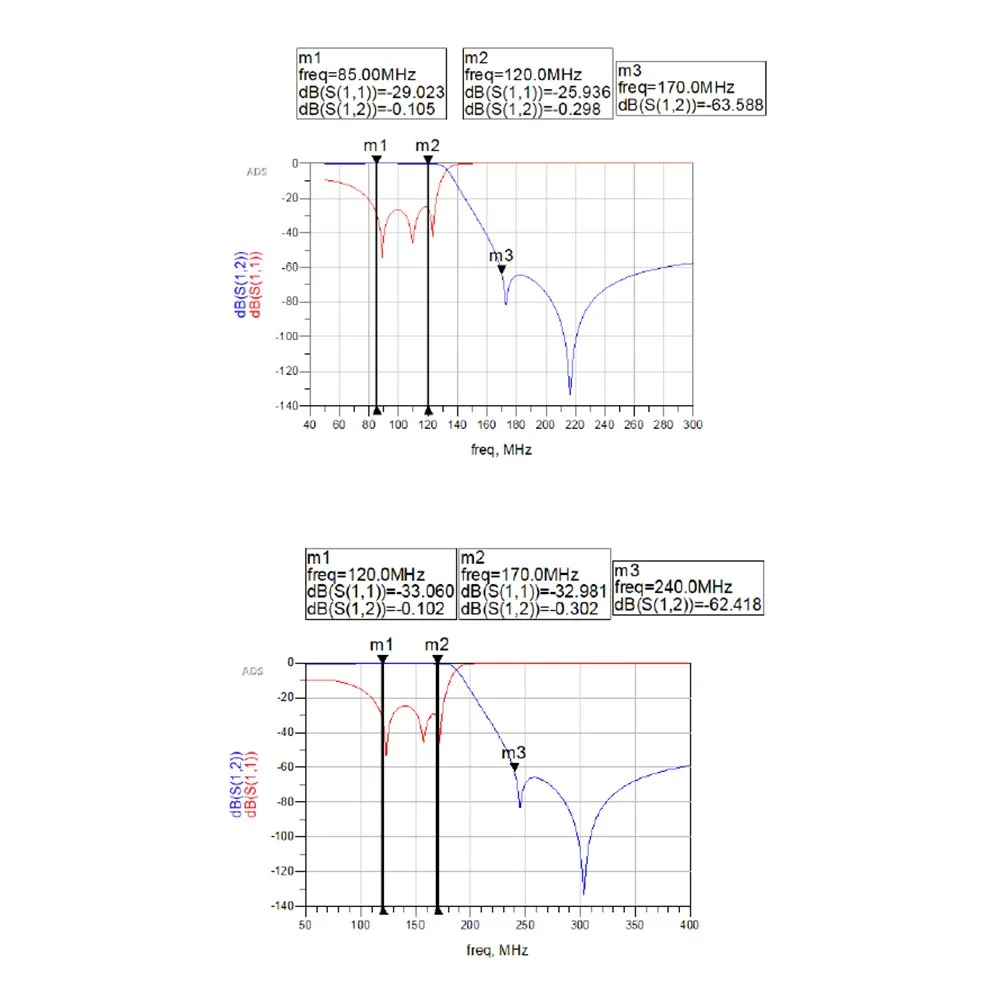 Image 4 of 6
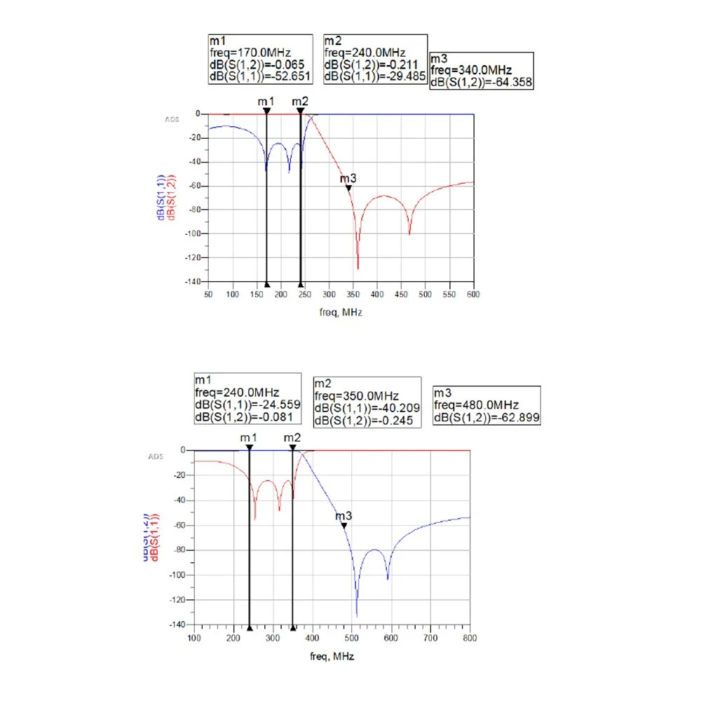 Image 5 of 6
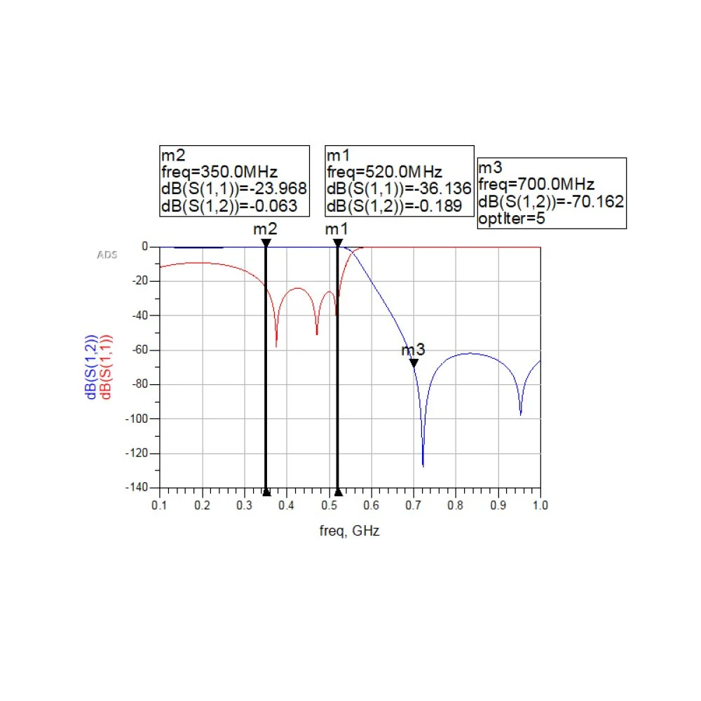 Image 6 of 6
| Parameter | Specification |
|---|---|
| Technique Characteristics | |
| Frequency (MHz) | 30 ~ 520 MHz |
| Output Power | 50 (+2.5/-0.5) dBm, 100W TYP. (120W Max) |
| Input Power | 0 ~ +5 dBm |
| Gain | 50 dB |
| Gain Flatness | ± 3 dB |
| Spurious Inhibition | > 70 dBc |
| Harmonic Suppression | 2nd, 3rd, 4th, 5th > 50 dBc @100W |
| Input Port VSWR | < 2.0 |
| IMD | Nominal 18 dBc at 3 dB total back-off from rated power |
| In-band Noise | < -90 dB/Hz |
| Power Supply (VDC) | 28V |
| Current Consumption (A) | 15A |
| Weight | 2.5 kg |
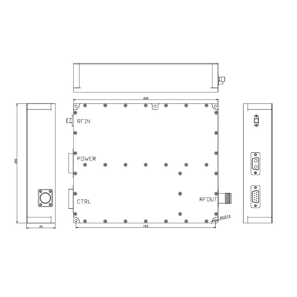
| Outer Dimension (mm) | MAX 200 × 200 × 40 mm (excluding connectors and handles) |
| Impedance | 50 Ω |
| Environment Condition | |
| Operating Temperature Range | -40°C to +65°C |
| Storage Temperature Range | -40°C to +85°C |
| Relative Humidity | 5% - 95% |
| Barometric Pressure | 55 kPa - 106 kPa |
| Vibration, Shock, Drop | MIL-STD-810H |
| EMI/EMC | MIL-STD-461E/461F or MIL-STD-461G |
RF Interface
| No | Name | Function | Model |
|---|---|---|---|
| 1 | RF IN | RF IN | SMA-Female |
| 2 | RF OUT | RF OUT | N-Female |
Power Interface D-sub
| No | Name | Function | Remark |
|---|---|---|---|
| A1 | +28V | Power In | |
| A2 | GND | Power In |
Control Interface DB-9 Male
| No | Name | Function | Remark |
|---|---|---|---|
| 1 | PA-EN | PA Enable (3.3–5V ON, 0–0.3V OFF) | TTL, “High” = “ON” |
| 2 | VF | Forward power detection (0–3V) | Analog |
| 3 | VR | Reverse power detection (0–3V) | Analog |
| 4 | VT | Temperature detection: 0.02V/°C (VT = 1V @ 0°C) | Analog |
| 5 | GR | Over Temperature Indicate | TTL, “High” = “Yes” |
| 6 | A2 | Address code of filter | TTL |
| 7 | A1 | Address code of filter | TTL |
| 8 | A0 | Address code of filter | TTL |
| 9 | -- | NC |
Amplifier Band Truth-Table
| A2 | A1 | A0 | Band | Freq-Range |
|---|---|---|---|---|
| 1 | 1 | 1 | 1 | 30MHz–45MHz |
| 1 | 1 | 0 | 2 | 45MHz–70MHz |
| 1 | 0 | 1 | 3 | 70MHz–100MHz |
| 1 | 0 | 0 | 4 | 100MHz–150MHz |
| 0 | 1 | 1 | 5 | 150MHz–240MHz |
| 0 | 1 | 0 | 6 | 240MHz–360MHz |
| 0 | 0 | 1 | 7 | 360MHz–520MHz |
1: TTL High Level (3.3V–5V)
0: TTL Low Level (0V–0.3V)
0: TTL Low Level (0V–0.3V)
Power Amplifier Performance (Pout = 120W, V = 28V)
| F (MHz) | Pin (dBm) | I (A) | Harmonic 2nd (dBc) | Harmonic 3rd (dBc) |
|---|---|---|---|---|
| 20 | 30.6 | 5.2 | 24.5 | 10.2 |
| 50 | 30.5 | 5.6 | 29.3 | 12.4 |
| 110 | 32.5 | 6.4 | 30.7 | 10.2 |
| 150 | 33.2 | 6.8 | 33.2 | 10.8 |
| 200 | 34.0 | 7.1 | 36.8 | 10.3 |
| 250 | 32.2 | 6.9 | 42.5 | 17.8 |
| 300 | 31.5 | 7.3 | 41.6 | 22.3 |
| 350 | 32.0 | 7.7 | 46.6 | 40.7 |
| 400 | 31.5 | 7.6 | 48.7 | 44.5 |
| 450 | 32.5 | 8.3 | 46.3 | 36.6 |
| 500 | 36.3 | 11.8 | 58.0 | 25.4 |
| 520 | 36.5 | 10.8 | 56.3 | 36.8 |