E-Band Coupler (60 GHz – 90 GHz)
Product Features :
High frequency, ultra-wide bandwidth
High coupling, high flatness
Low loss, high power handling
Operating temperature: -55℃~85℃
Overview An E-band coupler is a passive microwave component designed to sample, split, or combine signals in the 60–90 GHz frequency range. E-band spans millimeter-wave frequencies used for high-capacity wireless backhaul, point-to-point links, fixed wireless access, radar, and communications for 5G and beyond. Couplers for this band must meet tight tolerances for insertion loss, isolation, amplitude/phase balance, and return loss due to short wavelengths and sensitivity to manufacturing errors.
Key Types
Directional coupler: Samples a defined fraction of power from a main transmission path while isolating the coupled port from the reverse direction. Common coupling values: 3 dB (splitter), 6–20 dB (monitoring/measurement), higher for very low sampling.
Hybrid coupler (90°/180°): Used for power combining/splitting, phased arrays, and balanced mixers. Offers precise amplitude and phase relationship between outputs.
Magic-T (waveguide hybrid): Employed in waveguide implementations for combining and isolation in transmit/receive or measurement systems.
Construction & Technologies
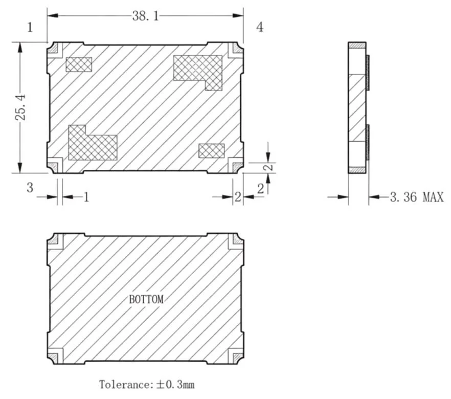
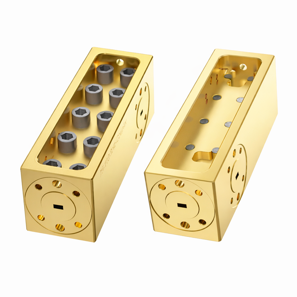
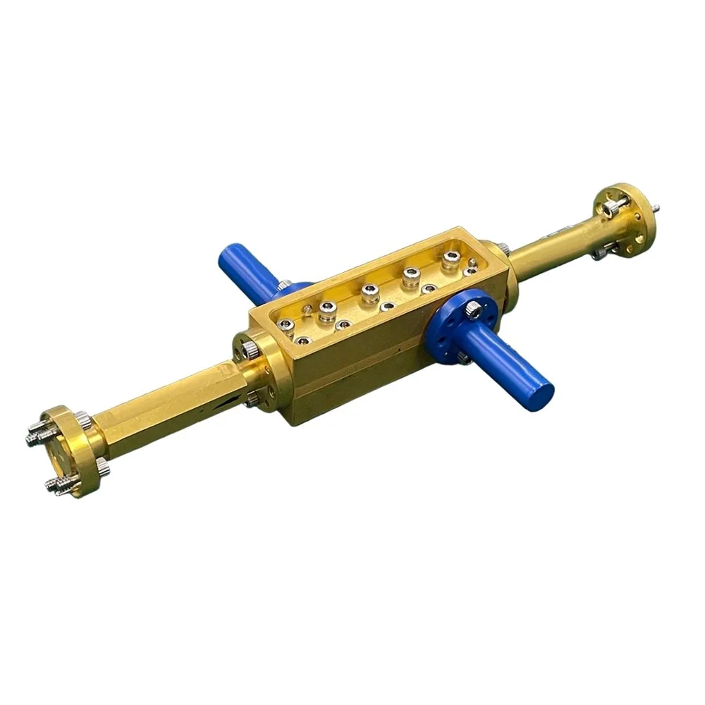
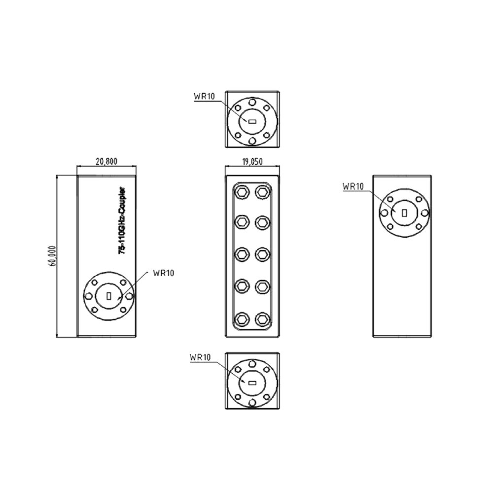
Waveguide couplers: Rectangular or ridge waveguides (WR-12 covers 60–90 GHz). Offer low loss and high power handling. Precision machining (CNC) or electroforming required.
Substrate-integrated waveguide (SIW): Integrates waveguide behavior on PCB substrates for compactness and integration with circuit traces. Good for mass-produced modules though somewhat higher loss than metallic waveguides.
Microstrip/CPW couplers: Easier to integrate with active circuitry on MMICs or PCBs, but higher losses and dispersion at E-band unless using very low-loss substrates and careful design.
Quasi-optical/planar couplers: Lens-fed or waveguide-to-antenna couplers for specific system architectures.
Typical Specifications
Frequency range: 60–90 GHz (some designs optimized for narrower sub-bands)
Coupling value: 3 dB to 30 dB (specified at center frequency or as flat over band)
Insertion loss (through port): as low as 0.2–1.5 dB for high-quality waveguide designs; higher for planar implementations
Directivity/isolation: 20–40 dB typical for precision directional couplers
Return loss (S11): >12–20 dB preferred across the band
Amplitude balance: ±0.1–0.5 dB for hybrids used in phased arrays
Phase balance: ±1–5 degrees depending on type and quality
Power handling: limited by connector/waveguide and thermal design; high-power waveguide couplers handle tens to hundreds of watts CW with proper cooling
Design Considerations
Manufacturing tolerance: At E-band, micron-level dimensional accuracy impacts performance. Thermal expansion and surface finish also affect loss and match.
Frequency scaling: Broadband performance across 60–90 GHz is challenging; many products target sub-bands (e.g., 71–86 GHz) for flatter response.
Transition design: Efficient, low-reflection transitions between waveguide and planar circuits or coax require careful tapering and mode conversion.
Integration: For compact radios, coupler choice depends on tradeoffs between insertion loss, size, weight, and manufacturability.
Isolation vs. coupling: Higher directivity improves measurement and isolation but often increases complexity and size.
Environmental and mechanical robustness: Outdoor E-band links need couplers that resist moisture, temperature cycling, and vibration.
Applications
Wireless backhaul and fronthaul for mobile networks: Monitoring, calibration, and combining/splitting signals in high-capacity links.
Test and measurement: Directional couplers sample signals for power meters, spectrum analyzers, and vector network analyzers in millimeter-wave test setups.
Phased arrays and beamforming: Hybrids and equal-split couplers distribute LO or RF signals with controlled phase for array feeding networks.
Radar and sensing: Couplers used in transmit/receive modules, isolating receive paths from transmit leakage.
Satellite ground stations and point-to-point microwave links: Low-loss waveguide couplers in high-performance links.

 Image 1 of 4
 Image 2 of 4
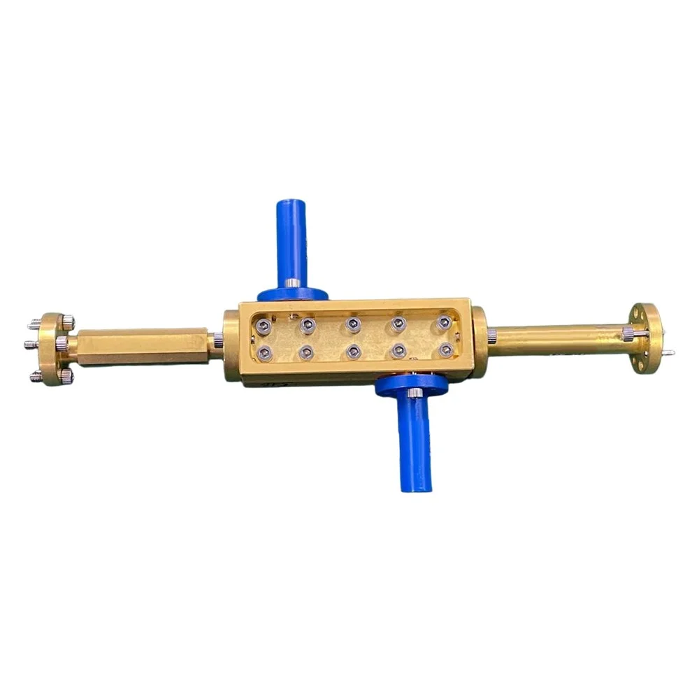 Image 3 of 4
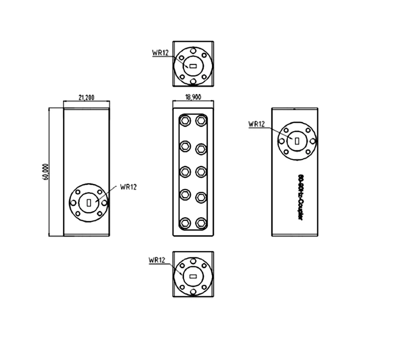 Image 4 of 4