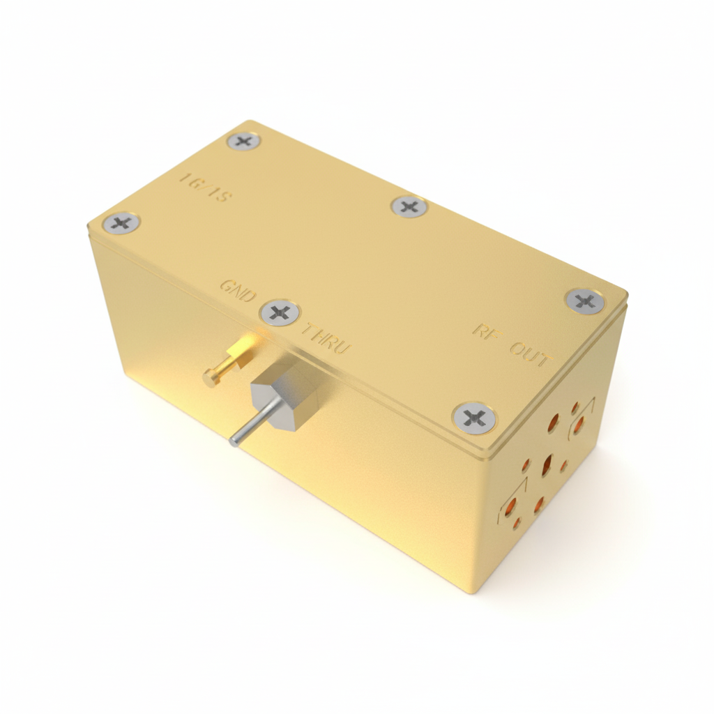
Image 1 of 3
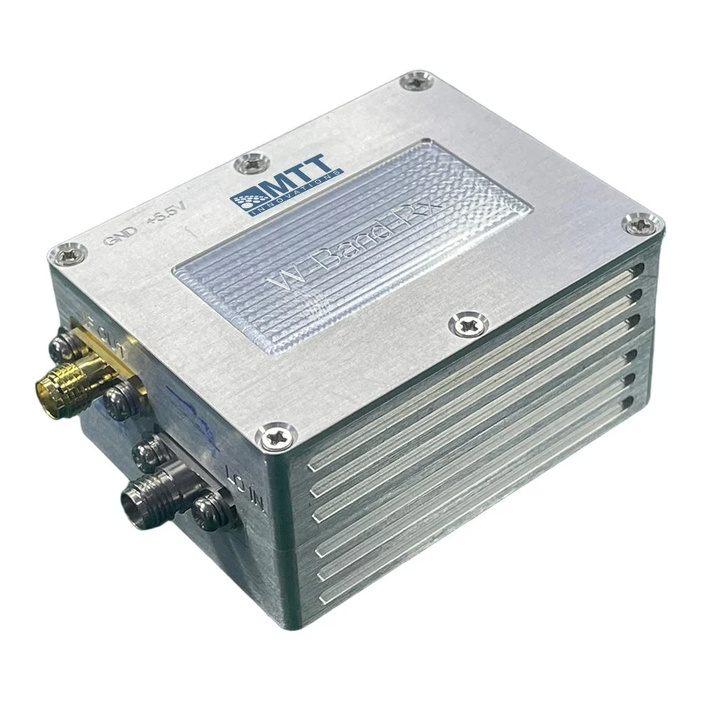
 Image 2 of 3
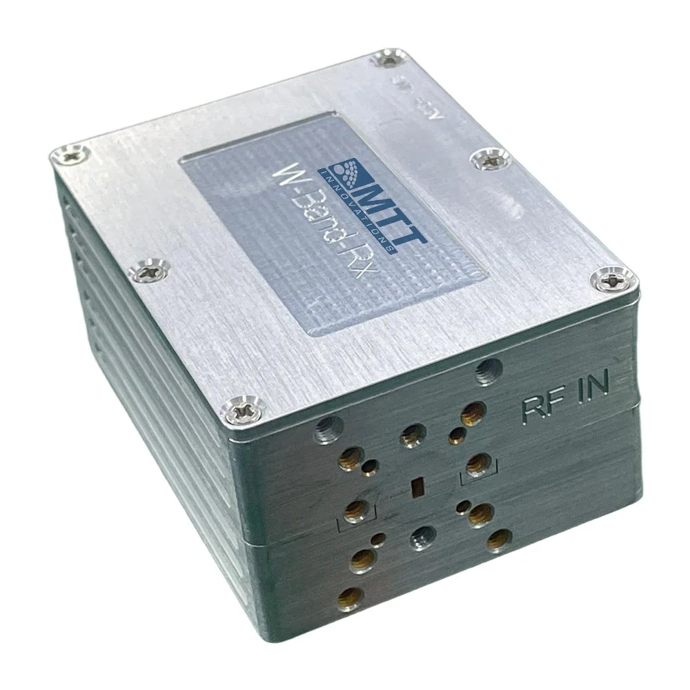
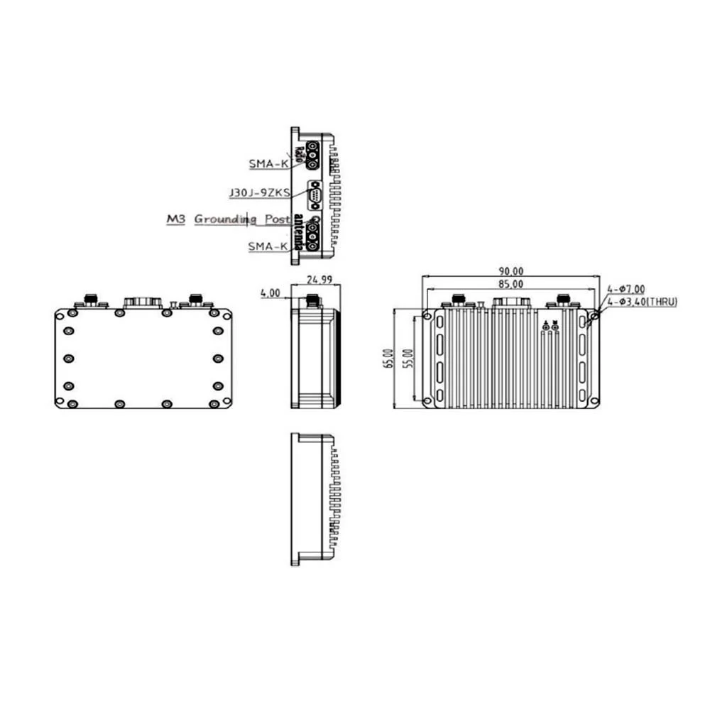 Image 3 of 3
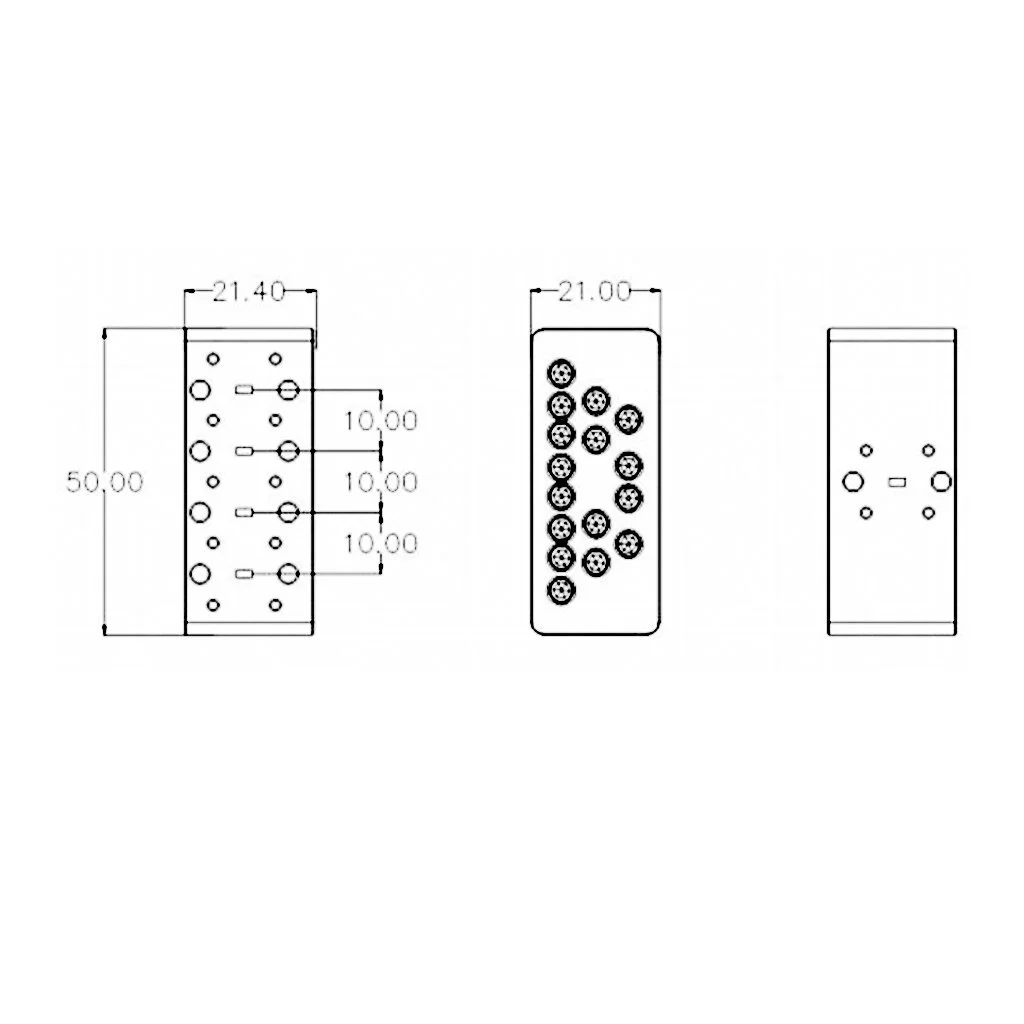
J30J Interface Pin Definitions
| Pin | Description | Remarks |
|---|---|---|
| 1 | GND | Power Ground |
| 2 | GTR_IN | Transmit/Receive Switching |
| 3 | GND | Power Ground |
| 4 | +28V | Power Supply |
| 5 | +28V | Power Supply |
| 6 | GTR_IN | Transmit/Receive Switching |
| 7 | GND | Power Ground |
| 8 | GND | Power Ground |
| 9 | +28V | Power Supply |