 Image 1 of 6
 Image 2 of 6
 Image 3 of 6
 Image 4 of 6
 Image 5 of 6
 Image 6 of 6
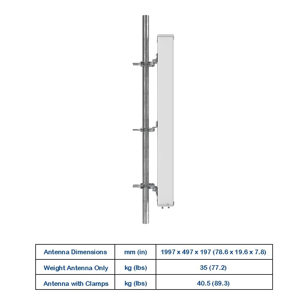
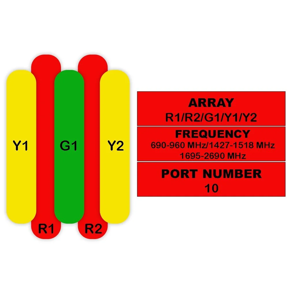
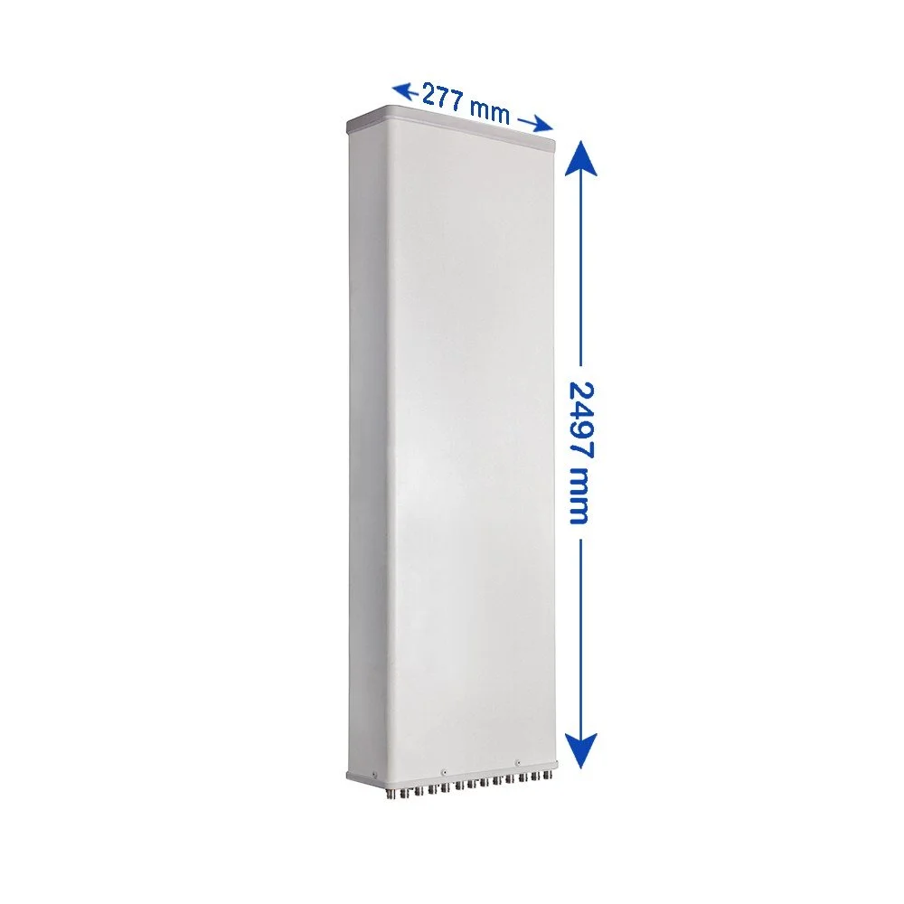
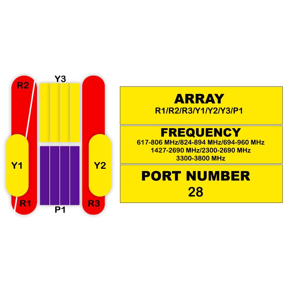
| Electrical Specifications | R1/R2 | Y1/Y4 | Y2/Y3 | |||||||||||||
|---|---|---|---|---|---|---|---|---|---|---|---|---|---|---|---|---|
| 690-960 | 1695-2690 | 1695-2690 | ||||||||||||||
| 690-806 | 790-894 | 1695-1880 | 1880-1990 | 1920-2170 | 2300-2400 | 2490-2690 | 1880-1990 | 1920-2170 | 2300-2400 | 2490-2690 | ||||||
| Polarization | ... | ±45° | ||||||||||||||
| Gain | dBi | 16 | 16.4 | 16.8 | 16.2 | 16.6 | 17 | 17.4 | 16.3 | 16.6 | 17.1 | 17.3 | 17.2 | |||
| Over all Tilts | dBi | 15.8±0.6 | 16.2±0.6 | 16.6±0.6 | 16.0±0.5 | 16.4±0.5 | 16.8±0.5 | 17.0±0.5 | 16.1±0.5 | 16.4±0.5 | 16.9±0.5 | 17.1±0.5 | 17.0±0.5 | |||
| Horizontal Beamwidth | degree | 68±5 | 66±4.5 | 64±6.5 | 66±6.5 | 68±7.5 | 66±7.5 | 62±6.5 | 66±6.5 | 64±7.5 | 61±7.5 | 61±6.5 | 63±7.0 | |||
| Vertical Beamwidth | degree | 8.8±0.9 | 7.8±0.7 | 7.2±0.6 | 6.8±0.8 | 6.4±0.5 | 6.0±0.4 | 5.2±0.5 | 6.8±0.8 | 6.4±0.5 | 6.0±0.4 | 5.2±0.5 | 4.8±0.5 | |||
| Electrical Downtilt | degree | 2-12 | 2-12 | 2-12 | ||||||||||||
| Continuously Adjustable | ... | |||||||||||||||
| Tilt Accuracy | degree | <1 | <1 | <1 | <1 | <1 | <1 | <1 | <1 | <1 | <1 | <1 | <1 | |||
| First Upper Side Lobe Suppression | dB | >16 | >16 | >16 | >16 | >16 | >16 | >16 | >16 | >16 | >16 | >16 | >16 | |||
| 20 Sector Above Main Beam | dB | >15 | >15 | >15 | >15 | >15 | >15 | >15 | >15 | >15 | >15 | >15 | >15 | |||
| Front-to-Back Ratio ±30° | dB | >23 | >24 | >25 | >23 | >24 | >24 | >25 | >25 | >24 | >25 | >25 | >25 | >25 | ||
| Cross-Polar Discrimination | dB | >17 | >18 | >17 | >16 | >17 | >16 | >17 | >17 | >16 | >16 | >16 | >16 | >17 | ||
| In Boresight | dB | >7 | >8 | >8 | >7 | >6 | >6 | >4 | >3 | >7 | >6 | >6 | >4 | >3 | ||
| Over Sector | dB | >26 | >26 | >26 | ||||||||||||
| Cross-Polar | dB | >28 | >28 | >28 | ||||||||||||
| Isolation | dB | >14 | >14 | >14 | ||||||||||||
| Interband (Typical) | dB | >0.6 | >0.6 | >0.6 | ||||||||||||
| Impedance | Ohm | 50 | 50 | 50 | ||||||||||||
| VSWR | ... | <1.5 | <1.5 | <1.5 | ||||||||||||
| Return Loss | dB | >14 | >14 | >14 | ||||||||||||
| PIM3 (2x43 dBm Carrier) | dBc | <-150 | <-150 | <-150 | ||||||||||||
| Lightning Protection | ... | DC Ground | DC Ground | DC Ground | ||||||||||||
| Maximum Average Input Power per Port @ 50°C | Watts | 250 | 200 | 200 | ||||||||||||
| Electrical Specifications | Y5 | P1 | |||
|---|---|---|---|---|---|
| MHz | MHz | MHz | MHz | ||
| Frequency Range | MHz | 2300-2690 | 3300-3800 | ||
| ... | ... | 2300-2400 | 2490-2690 | 3300-3800 | 3600-3800 |
| Polarization | ... | ||||
| Electrical Downtilt, Continuously Adjustable |
degree | 2-12 | 2-12 | ||
| ... | |||||
| Gain | dBi | 16.5 ± 1 | 17.5 ± 1 | 15.5 ± 1 | 15.7 ± 1 |
| Horizontal Beamwidth | degree | 80 ± 10 | 75 ± 10 | 75 ± 10 | 65 ± 10 |
| Vertical Beamwidth (3 dB) | degree | 5.4 ± 0.5 | 5.0 ± 0.5 | 5.8 ± 0.6 | 5.5 ± 0.6 |
| Cross-Polar Discrimination (0°) | dB | ≥16 | ≥16 | ≥15 | ≥15 |
| First Upper Side Lobe Suppression | dB | ≥15 | ≥15 | ≥15 | ≥15 |
| Front-to-Back Ratio | dB | ≥28 | ≥28 | ≥25 | ≥25 |
| Gain Of Broadcasting Pattern (Typical) | dBi | 17.5 ± 1 | 18 ± 1 | 17.0 ± 0.6 | 17.2 ± 0.6 |
| Horizontal Beamwidth | degree | 65 | 65 | 65 | 65 |
| Vertical Beamwidth | degree | 5.4 ± 0.5 | 5.0 ± 0.5 | 5.8 ± 0.6 | 5.5 ± 0.6 |
| Cross-Polar Discrimination At Boresight | dB | ≥16 | ≥16 | ≥15 | ≥15 |
| dB | ≥28 | ≥28 | ≥27 | ≥27 | |
| Front-to-Back Ratio | dB | ≥22 ± 1 | ≥22 ± 1 | ≥21 ± 0.5 | ≥21.2 ± 0.5 |
| Direct Beam Gain | dBi | 22 ± 3 | 21 ± 3 | 24 ± 2 | 25 ± 2 |
| Horizontal 3 Db Beamwidth | degree | 20 ± 1 | 20 ± 1 | 18 | 18.2 |
| ±30 Direction Beam Gain | dBi | 20 ± 1 | 20 ± 1 | ||
| Beam Cross Polar Ratio | dB | ≥20 | ≥20 | ||
| Horizontal Sidelobe Suppression | dB | ≥12 | ≥12 | ||
| Front-to-Back Ratio | dB | ≥30 | ≥30 | ||
| Gain | dBi | 20.5 ± 1 | 21 ± 1 | ||
| Horizontal Beamwidth | degree | 30 ± 3 | 28 ± 3 | ||
| Vertical Beamwidth (3 dB) | degree | 5.4 ± 0.5 | 5.0 ± 0.5 | ||
| First Upper Sidelobe Suppression | dB | ≥17 | ≥17 | ||
| Front-to-Back Ratio | dB | ≥28 | ≥28 | ||
| Coupling Factor Between Calibration Port And Each Antenna Port | dB | ≤ -26 ± 2 | |||
| ... | |||||
| Max. Amplitude Tolerance From Calibration Port To Input Ports | dB | ≤0.9 | |||
| Max. Phase Tolerance From Calibration Port To Input Ports | degree | ≤5.7 | |||
| Port-to-Port VSWR | ... | ≤1.5 | |||
| Return Loss | dB | ≥14 | |||
| Max. Average Input Power per RF Port | Watts | 150 | |||
| Co-Polarization Isolation Between Ports | dB | ≥25 | |||
| Cross-Polar Isolation Between Ports | dB | ≥25 | |||
Hello, World!