 Image 1 of 6
 Image 2 of 6
 Image 3 of 6
 Image 4 of 6
 Image 5 of 6
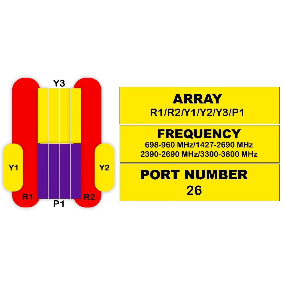 Image 6 of 6
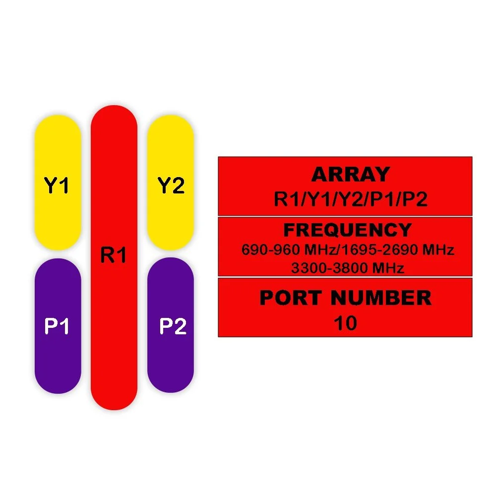
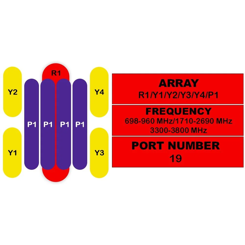
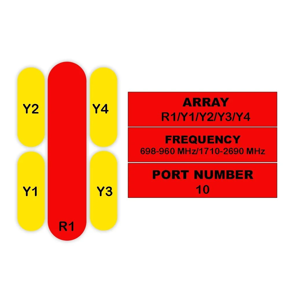
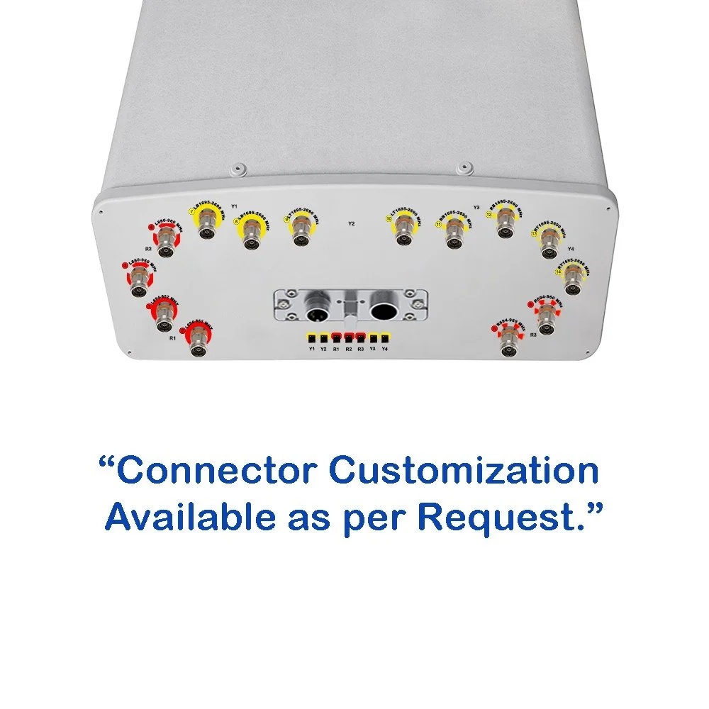
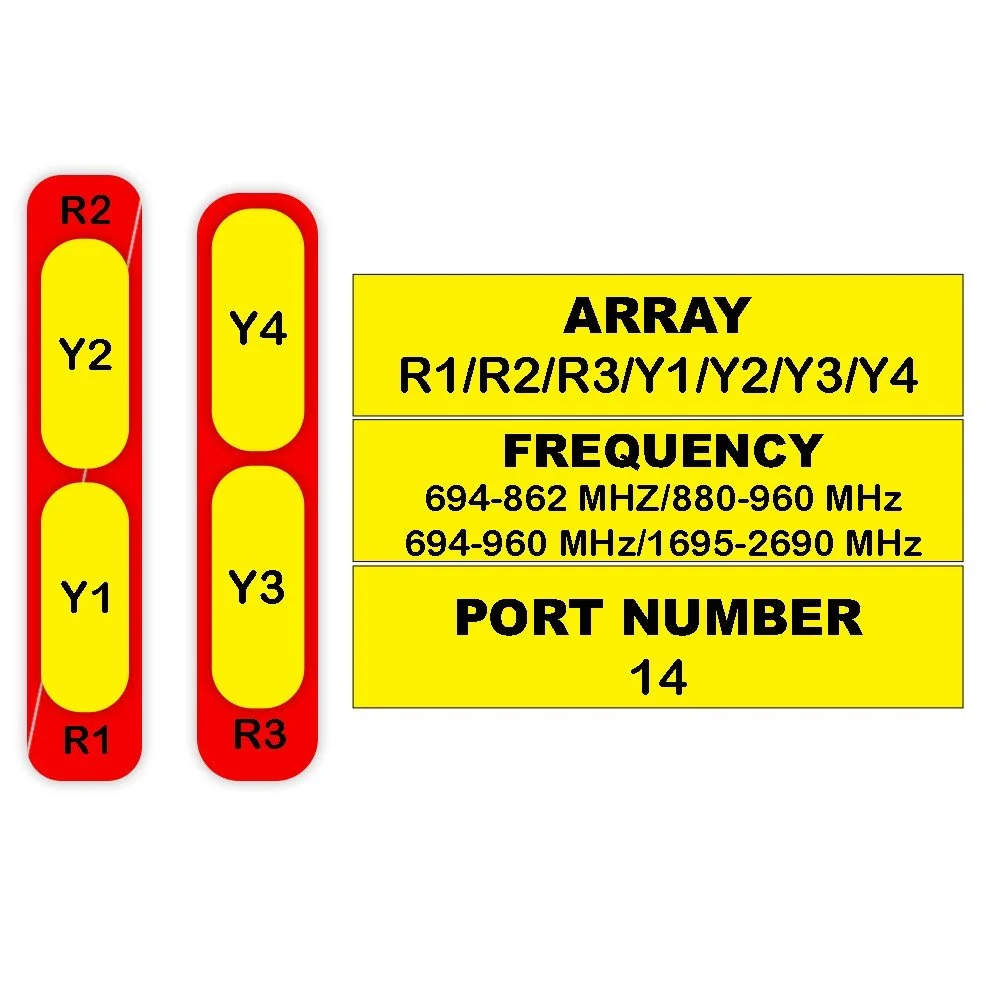
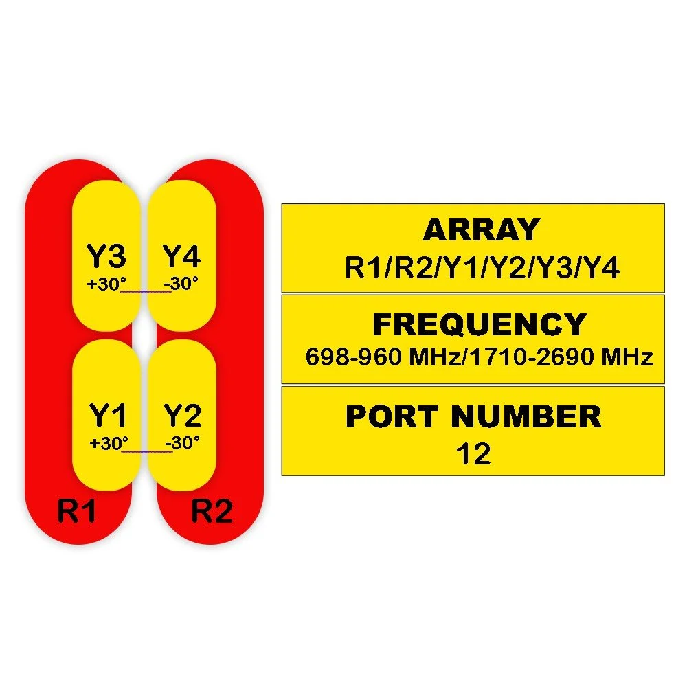
| R1 / R2 | Y1 / Y2 | ||||||||
|---|---|---|---|---|---|---|---|---|---|
| 698-806 | 790-894 | 880-960 | 1427-1518 | 1695-1920 | 1920-2170 | 2300-2400 | 2500-2690 | ||
| Frequency Range | MHz | 698-960 | 1427-2690 | ||||||
| MHz | 698-806 | 790-894 | 880-960 | 1427-1518 | 1695-1920 | 1920-2170 | 2300-2400 | 2500-2690 | |
| Polarization | — | ±45° | ±45° | ||||||
| Gain | at Mid Tilt (dBi) | 15.8 | 16.1 | 16.4 | 15.7 | 16.6 | 17.2 | 17.4 | 17.4 |
| Over All Tilts (dBi) | 15.6 ± 0.5 | 15.9 ± 0.5 | 16.2 ± 0.5 | 15.5 ± 0.6 | 16.4 ± 0.5 | 17.0 ± 0.5 | 17.2 ± 0.5 | 17.2 ± 0.5 | |
| Horizontal Beamwidth | degree | 66 ± 6.5 | 62 ± 6.0 | 58 ± 6.5 | 70 ± 8.0 | 66 ± 8.0 | 65 ± 7.0 | 61 ± 6.5 | 61 ± 8.0 |
| Vertical Beamwidth | degree | 8.4 ± 0.8 | 7.8 ± 0.6 | 7.2 ± 0.6 | 8.1 ± 0.6 | 6.6 ± 0.8 | 5.9 ± 0.6 | 5.2 ± 0.5 | 4.8 ± 0.6 |
| Electrical Downtilt, Continuously Adjustable | degree | 2-12 | 2-12 | ||||||
| First Upper Side Lobe Suppression | dB | > 15 | > 15 | > 15 | > 15 | > 15 | > 15 | > 15 | > 15 |
| Front-To-Back Ratio Co-Polar ±30° | dB | > 23 | > 24 | > 25 | > 22 | > 24 | > 25 | > 23 | > 23 |
| Cross Polar Discrimination At Boresight | dB | > 17 | > 18 | > 17 | > 15 | > 16 | > 16 | > 16 | > 16 |
| Isolation | Cross-Polar (dB) | > 25 | > 25 | ||||||
| Interband (typical, dB) | > 25 | > 25 | |||||||
| Impedance | Ohm | 50 | 50 | ||||||
| VSWR | — | < 1.5 | < 1.5 | ||||||
| Return Loss | dB | > 14 | > 14 | ||||||
| PIM3 (2x43 dBm Carrier) | dBc | < -150 | < -150 | ||||||
| Lightning Protection | — | DC Ground | DC Ground | ||||||
| Maximum Average Input Power per Port, at 50°C Ambient Temperature | Watts | 250 | 200 | ||||||
| Specification | Unit | 2300-2400 MHz | 2490-2690 MHz |
|---|---|---|---|
| Frequency Range | MHz | 2300-2690 | |
| Polarization | — | ±45° | |
| Electrical Downtilt, Continuously Adjustable | degree | 2–12 | |
| Single Column Beam | |||
| Gain | dBi | 15.5 ± 1 | 16 ± 1 |
| Horizontal Beamwidth | degree | 80 ± 15 | 75 ± 15 |
| Vertical Beamwidth (3 dB) | degree | 6.0 ± 0.6 | 5.5 ± 0.6 |
| Cross-Polar Discrimination At Boresight (0°) | dB | 16 | 16 |
| First Upper Side Lobe Suppression | dB | ≥ 16 | ≥ 16 |
| Front-To-Back Ratio, Co-Pol ±30° | dB | ≥ 25 | ≥ 25 |
| 65° Broadcast Beam | |||
| Gain | dB | 16.5 | 17 |
| Horizontal Beamwidth (10 dB) | degree | 115 | 108 |
| Vertical Beamwidth (3 dB) | degree | 6.0 ± 0.6 | 5.5 ± 0.6 |
| Cross-Polar Discrimination At Boresight (0°) | dB | 16 | 16 |
| First Upper Side Lobe Suppression | dB | ≥ 16 | ≥ 16 |
| Front-To-Back Ratio | dB | ≥ 25 | ≥ 25 |
| Service Beam | |||
| 0° Direct Beam Gain | dBi | 20 | 20.5 |
| 0° Direct Beam Horizontal 3 dB Beamwidth | degree | 26 | 24 |
| 0° Direct Beam Cross-Polar Ratio | dB | 18 | 18 |
| 0° Direct Beam Front-To-Back Ratio, Co-Polar | dB | ≥ 28 | ≥ 28 |
| 0° Direct Beam Horizontal Sidelobe Suppression | dB | 12 | 12 |
| ±30° Direction Beam Gain | dBi | 18.5 | 19 |
| ±30° Direction Beam Horizontal 3 dB Beamwidth | degree | 29 | 26 |
| ±30° Direction Beam Front-To-Back Ratio, Co-Polar | dB | ≥ 28 | ≥ 28 |
| Soft Split Multi-Beam | |||
| Gain | dBi | 19 | 19.5 |
| Horizontal Beamwidth (3 dB) | degree | 30 | 28 |
| Vertical Beamwidth (3 dB) | degree | 6.0 ± 0.6 | 5.5 ± 0.6 |
| First Upper Side Lobe Suppression | dB | ≥ 16 | ≥ 16 |
| Front-To-Back Ratio, Co-Polar | dB | ≥ 25 | ≥ 25 |
| Calibration & Electrical Parameter | |||
| Coupling Factor Between Calibration And Each Antenna Port | dB | -26 ± 2 | |
| Maximum Amplitude Tolerance From Calibration Port To Input Ports | dB | ≤ 1.0 | |
| Maximum Phase Tolerance From Calibration Port To Input Ports | degree | ≤ 9 | |
| Ports VSWR | — | < 1.5 | |
| Return Loss | dB | > 14 | |
| Average Power Capacity | W | 50 | |
| Co-Polar Isolation Between Ports | dB | ≥ 25 | |
| Inter-band Isolation | dB | ≥ 25 | |
| PIM3 (2x43 dBm Carrier) | dBc | < -143 | |
| Impedance | Ohms | 50 | |
| Lightning Protection | — | DC Ground | |
| TDD LTE Electrical Specifications | Unit | P1 | ||
|---|---|---|---|---|
| 3300-3600 MHz | 3600-3800 MHz | |||
| Frequency Range | MHz | 3300-3800 | ||
| Polarization | -- | ±45° | ||
| Electrical Downtilt, Continuously Adjustable | degree | 2-12 | ||
| Single Column Beam | Gain | dBi | 15.1 ± 1 | 15.5 ± 1 |
| Horizontal Beamwidth | degree | 75 ± 15 | 70 ± 15 | |
| Vertical Beamwidth (3 dB) | degree | 6.6 ± 0.8 | 6.0 ± 0.6 | |
| Cross-Polar At Boresight (0°) | dB | ≥ 15 | ≥ 15 | |
| Discrimination Over Sector | dB | ≥ 8 | ≥ 8 | |
| First Upper Side Lobe Suppression | dB | ≥ 15 | ≥ 15 | |
| Front-To-Back Ratio | dB | ≥ 23 | ≥ 23 | |
| 65° Broadcast Beam | Gain | dB | 16.5 | 17 |
| Horizontal Beamwidth (10 dB) | degree | 115 | 108 | |
| First Upper Side Lobe Suppression | dB | ≥ 15 | ≥ 15 | |
| Front-To-Back Ratio, Co-Polar | dB | ≥ 25 | ≥ 25 | |
| Service Beam | 0° Direct Beam Gain | dBi | 20.5 | 21 |
| 0° Direct Beam Horizontal 3 dB Beamwidth | degree | 26 | 24 | |
| 0° Direct Beam Cross-Polar Ratio at Beampeak | dB | ≥ 16 | ≥ 17 | |
| 0° Direct Beam Front-To-Back Ratio, Co-Polar | dB | ≥ 27 | ≥ 28 | |
| 0° Direct Beam Horizontal Sidelobe Suppression | dB | 12 | 12 | |
| ±30° Direction Beam Gain | dBi | 19 | 19.5 | |
| ±30° Direction Beam Horizontal 3 dB Beamwidth | degree | 28 | 25 | |
| ±30° Direction Beam Front-To-Back Ratio, Co-Polar | dB | ≥ 25 | ≥ 25 | |
| Soft Split Multi-Beam | Gain | dBi | 19.3 | 19.8 |
| Horizontal Beamwidth (3 dB) | degree | 31 | 29 | |
| Front-To-Back Ratio, Co-Polar | dB | ≥ 25 | ≥ 25 | |
| Coupling Factor Between Calibration And Each | dB | -26 ± 2 | ||
| Calibration and Electrical Parameter | Antenna Port | |||
| Maximum Amplitude Tolerance From Calibration Port To Input Ports | dB | ≤ 1.0 | ||
| Maximum Phase Tolerance From Calibration Port To Input Ports | degree | ≤ 9 | ||
| Ports VSWR | -- | < 1.5 | ||
| Average Power Capacity | W | 25 | ||
| Co-Polar Isolation Between Ports | dB | ≥ 23 | ||
| Inter-band Isolation | dB | ≥ 23 | ||
| Impedance | Ohms | 50 | ||
| Lightning Protection | -- | DC Ground | ||
| 5G Electrical Specifications | Unit | P1 | ||
|---|---|---|---|---|
| 3300-3600 MHz | 3600-3800 MHz | |||
| Frequency Range | MHz | 3300-3800 | ||
| Single Column Beam | Gain | dBi | 15.1 ± 1 | 15.5 ± 1 |
| Horizontal Beamwidth (3 dB) | degree | 75 ± 15 | 70 ± 15 | |
| Vertical Beamwidth (3 dB) | degree | 6.6 ± 0.8 | 6.0 ± 0.6 | |
| Cross-Polar At Boresight (0°) | dB | ≥ 15 | ≥ 15 | |
| Discrimination Over Sector | dB | ≥ 8 | ≥ 8 | |
| First Upper Side Lobe Suppression | dB | ≥ 15 | ≥ 15 | |
| Broadcast Beam (±13°, ±43° Service Beam) | Gain | dB | ≥ 15 | ≥ 15 |
| Horizontal Beamwidth | dB | 20 | 20.5 | |
| First Upper Side Lobe Suppression | degree | 65 | 65 | |
| Front-To-Back Ratio | dB | ≥ 15 | ≥ 15 | |
| Service Beam | 0° Direct Beam Gain | dB | ≥ 25 | ≥ 25 |
| 0° Direct Beam Horizontal 3 dB Beamwidth | dBi | 20.5 | 21 | |
| 0° Direct Beam Cross-Polar Ratio at Beampeak | degree | 26 | 24 | |
| dB | ≥ 16 | ≥ 17 | ||
| 0° Direct Beam Front-To-Back Ratio, Co-Polar | dB | ≥ 27 | ≥ 28 | |
| 0° Direct Beam Horizontal Sidelobe | dB | 12 | 12 | |