 Image 1 of 6
 Image 2 of 6
 Image 3 of 6
 Image 4 of 6
 Image 5 of 6
 Image 6 of 6
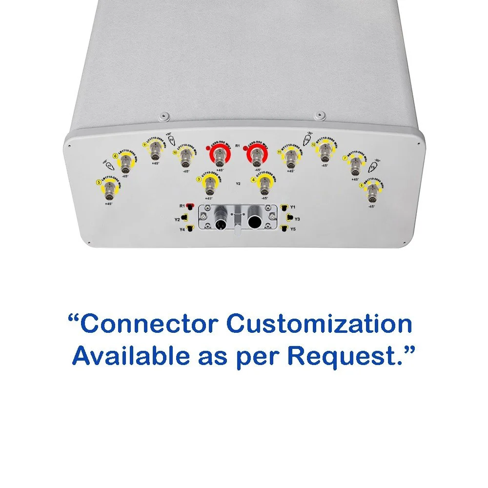
| Electrical Specifications | R1 / R2 | B1 / B2 | Y1 / Y4 | |
|---|---|---|---|---|
| Frequency Range | MHz | 694-960 | 1695-2180 | 1695-2180 |
| MHz | 694-806 / 790-894 / 880-960 | 1695-1880 / 1850-1990 / 1920-2180 | 2490-2690 | |
| Polarization | --- | ±45° | ±45° | ±45° |
| Gain | Typical (dBi) | 15.1 / 15.4 / 15.8 | 16.8 / 17.1 / 17.5 | 17.7 |
| Over All Tilts (dBi) | 14.5±0.6 / 14.8±0.6 / 15.2±0.6 | 16.2±0.6 / 16.6±0.5 / 17.0±0.5 | 17.2±0.5 | |
| Horizontal Beamwidth | degree | 68±5.4 / 65±5.6 / 62±4.6 | 66±6.5 / 66±6.5 / 64±8.1 | 58±9.0 |
| Vertical Beamwidth | degree | 11.6±1.1 / 10.3±0.6 / 9.2±0.7 | 6.2±0.6 / 5.6±0.8 / 5.2±0.8 | 4.4±0.5 |
| Electrical Downtilt, Continuously Adjustable | degree | 2-12 | 2-12 | 2-12 |
| Tilt Accuracy | degree | < 1 | < 1 | < 1 |
| Upper Side Lobe | First Upper Lobe (dB) | > 15 | > 15 | > 15 |
| Suppression | Peak to 20° (dB) | > 14 | > 15 | > 14 |
| Front-To-Back Ratio ±30° | dB | > 22 / > 23 / > 24 | > 24 / > 24 / > 25 | > 24 |
| Cross Polar | At Boresight (dB) | > 16 | > 18 | > 18 |
| Discrimination | Over Sector (dB) | > 7.0 / > 7.0 / > 6.0 | > 6.0 / > 7.0 / > 7.0 | > 2.0 |
| Isolation | Cross-Polar (dB) | > 25 | > 26 | > 26 |
| Interband (typical, dB) | > 25 | > 25 | > 25 | |
| Impedance | Ohm | 50 | 50 | 50 |
| VSWR | --- | < 1.5 | < 1.5 | < 1.5 |
| Return Loss | dB | > 14 | > 14 | > 14 |
| PIM3 (2x43 dBm Carrier) | dBc | < -150 | < -150 | < -150 |
| Lightning Protection | --- | DC Ground | DC Ground | DC Ground |
| Maximum Average Input Power per Port, at 50°C Ambient Temperature | Watts | 250 | 200 | 200 |
| Electrical Specifications | Y2 / Y3 | |||||
|---|---|---|---|---|---|---|
| Frequency Range (MHz) | 1427-1518 | 1695-1920 | 1920-2170 | 2300-2400 | 2500-2690 | |
| Polarization | --- | ±45° | ||||
| Gain | at Mid Tilt (dBi) | 15.4 | 16.6 | 17.2 | 17.6 | 17.6 |
| Over All Tilts (dBi) | 14.8 ± 0.6 | 16.0 ± 0.6 | 16.6 ± 0.6 | 17.0 ± 0.6 | 17.0 ± 0.6 | |
| Horizontal Beamwidth | degree | 71 ± 9.5 | 66 ± 8.5 | 59 ± 6.5 | 58 ± 6.0 | 57 ± 8.0 |
| Vertical Beamwidth | degree | 9.4 ± 0.6 | 7.9 ± 0.8 | 6.6 ± 0.6 | 6.0 ± 0.5 | 5.4 ± 0.6 |
| Electrical Downtilt, Continuously Adjustable | degree | 2-12 | ||||
| Tilt Accuracy | degree | < 1 | < 1 | < 1 | < 1 | < 1 |
| Upper Side Lobe Suppression | First Upper Side Lobe (dB) | > 15 | > 15 | > 15 | > 15 | > 15 |
| Peak to 20° (dB) | > 14 | > 14 | > 14 | > 14 | > 14 | |
| Front-To-Back Ratio ±30° | dB | > 23 | > 25 | > 25 | > 25 | > 25 |
| Cross Polar | At Boresight (dB) | > 16 | > 16 | > 16 | > 17 | > 17 |
| Discrimination | Over Sector (dB) | > 4.0 | > 6.0 | > 5.0 | > 3.0 | > 2.0 |
| Cross-Polar (dB) | > 25 | |||||
| Isolation | Port-to-Port (dB) | > 25 | ||||
| Impedance | Ohm | 50 | ||||
| VSWR | --- | < 1.5 | ||||
| Return Loss | dB | > 14 | ||||
| PIM3 (2x43 dBm Carrier) | dBc | < -150 | ||||
| Lightning Protection | --- | DC Ground | ||||
| Maximum Average Input Power per Port, at 50°C Ambient Temperature | Watts | 200 | ||||
| Parameter | Unit | P1 (3300-3800 MHz) |
3300-3600 | 3600-3800 |
|---|---|---|---|---|
| Frequency Range | MHz | 3300-3800 | 3300-3600 | 3600-3800 |
| Polarization | --- | ±45° | ||
| Electrical Downtilt, Continuously Adjustable | degree | 2-12 | ||
| Single Column Beam Gain | dBi | 15.0 ± 1 | 15.2 ± 1 | |
| Horizontal Beamwidth | degree | 80 ± 10 | 70 ± 10 | |
| Vertical Beamwidth (3 dB) | degree | 5.8 ± 0.6 | 5.5 ± 0.6 | |
| Cross-Polar Discrimination (0°) | dB | ≥ 15 | ≥ 15 | |
| First Upper Side Lobe Suppression | dB | ≥ 15 | ≥ 15 | |
| Front-To-Back Ratio | dB | ≥ 25 | ≥ 25 | |
| 65° Broadcast Beam Gain | dB | 16.5 ± 0.6 | 16.7 ± 0.6 | |
| Horizontal Beamwidth | degree | 65 | 65 | |
| Vertical Beamwidth (3 dB) | degree | 5.8 ± 0.6 | 5.5 ± 0.6 | |
| Cross-Polar Discrimination (0°) | dB | ≥ 15 | ≥ 15 | |
| First Upper Side Lobe Suppression | dB | ≥ 15 | ≥ 15 | |
| Front-To-Back Ratio | dB | ≥ 27 | ≥ 27 | |
| Service Beam 0° Direct Beam Gain | dBi | 20.5 ± 0.5 | 20.7 ± 0.5 | |
| 0° Direct Beam Horizontal 3 dB Beamwidth | degree | < 25 | < 25 | |
| ±30° Direction Beam Gain | dBi | 17.5 | 17.7 | |
| ±30° Direction Beam Horizontal 3 dB Beamwidth | degree | < 30 | < 30 | |
| 0° Direct Beam Cross-Polar Ratio | dB | ≥ 18 | ≥ 18 | |
| 0° Direct Beam Front-To-Back Ratio | dB | ≥ 30 | ≥ 30 | |
| Coupling Factor Between Calibration And Each Antenna Port | dB | -26 ± 2 | ||
| Maximum Amplitude Tolerance From Calibration Port To Input Ports | dB | ≤ 0.7 | ||
| Maximum Phase Tolerance From Calibration Port To Input Ports | degree | ≤ 9 | ||
| Ports VSWR | --- | < 1.5 | ||
| Average Power Capacity | Watts | 25 | ||
| Co-Polar Isolation Between Ports | dB | ≥ 20 | ||
| Cross-Polar Isolation Between Ports | dB | ≥ 25 | ||
| Impedance | Ohm | 50 | ||
| VSWR | --- | < 1.5 | ||
| Return Loss | dB | > 14 | ||
| PIM3 (2×43 dBm Carrier) | dBc | < -140 | ||
| Lightning Protection | --- | DC Ground | ||