 Image 1 of 6
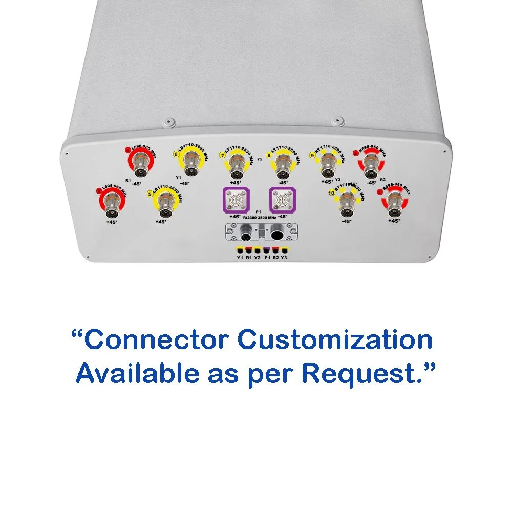 Image 2 of 6
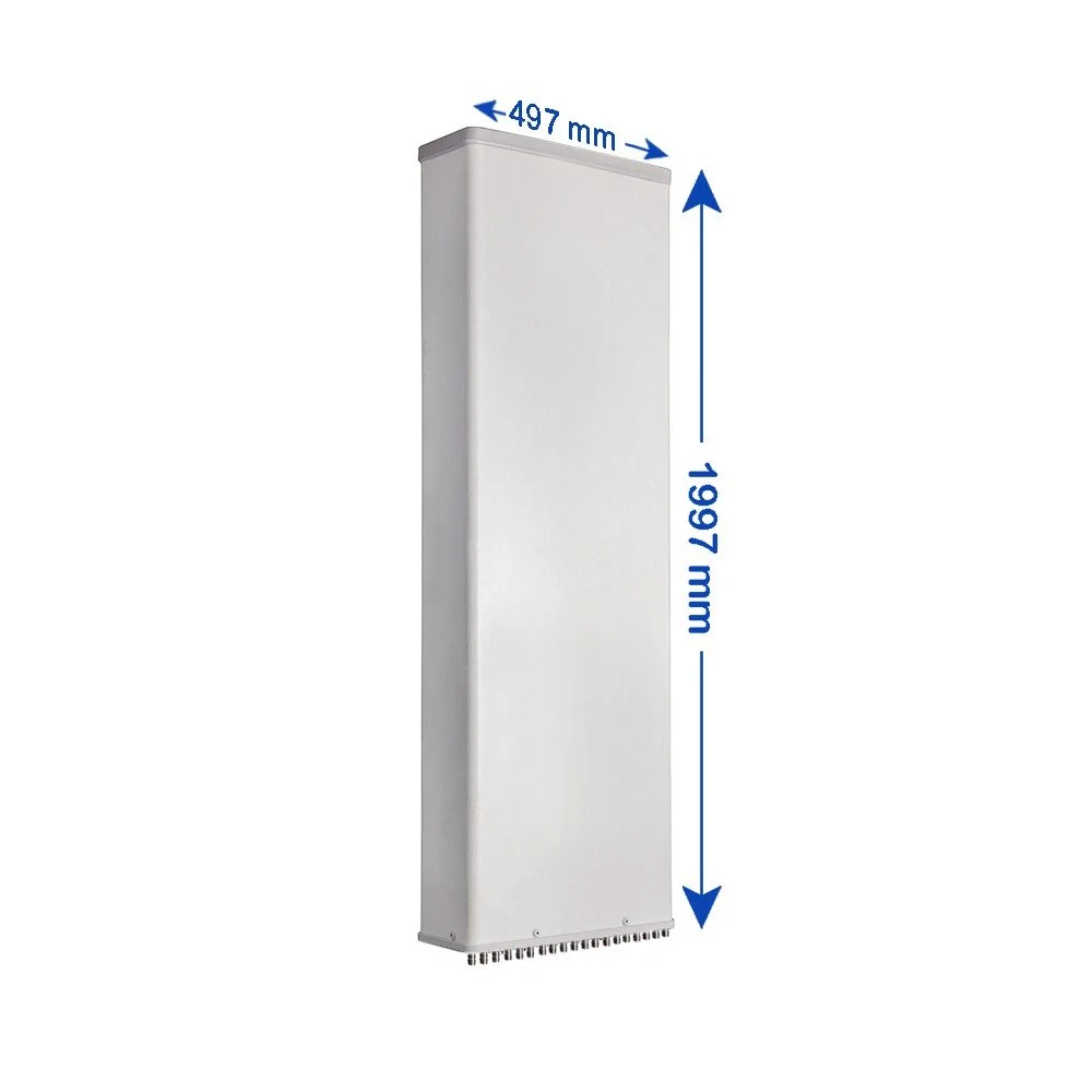 Image 3 of 6
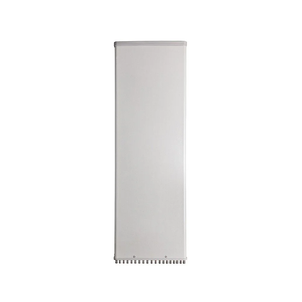 Image 4 of 6
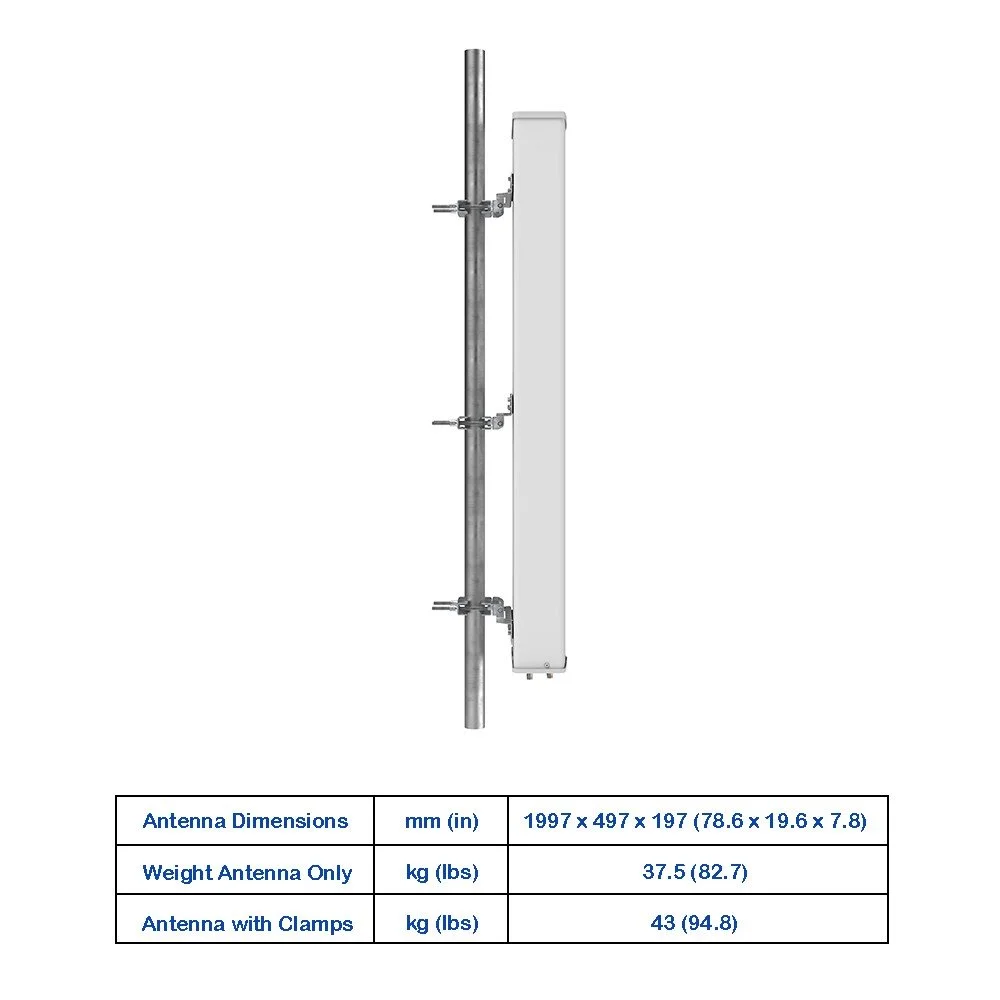 Image 5 of 6
 Image 6 of 6
Electrical Specifications
| Parameter | Unit | 698-806 | 790-894 | 880-960 | 1695-1880 | 1850-1990 | 1920-2170 | 2300-2400 | 2490-2690 |
|---|---|---|---|---|---|---|---|---|---|
| Gain at Mid Tilt (dBi) | dBi | 14.8 | 15.3 | 15.6 | 16.6 | 17.0 | 17.4 | 17.4 | 17.4 |
| Gain Over All Tilts (dBi) | dBi | 14.7 ± 0.6 | 15.2 ± 0.6 | 15.5 ± 0.6 | 16.4 ± 0.5 | 16.8 ± 0.5 | 17.2 ± 0.5 | 17.2 ± 0.5 | 17.2 ± 0.5 |
| Horizontal Beamwidth | degree | 66 ± 5 | 63 ± 5 | 59 ± 5 | 67 ± 7.5 | 65 ± 7.5 | 62 ± 7.0 | 63 ± 7.0 | 62 ± 7.5 |
| Vertical Beamwidth | degree | 10.5 ± 1 | 9.6 ± 1.0 | 9.0 ± 0.9 | 6.8 ± 0.6 | 6.4 ± 0.6 | 6.0 ± 0.6 | 5.2 ± 0.5 | 4.8 ± 0.4 |
| Electrical Downtilt (Adjustable) | degree | 2-12 | 2-12 | 2-12 | 2-12 | 2-12 | 2-12 | 2-12 | 2-12 |
| First Upper Side Lobe Suppression | dB | > 15 | > 15 | > 15 | > 16 | > 16 | > 16 | > 16 | > 16 |
| Front-To-Back Ratio ±30° | dB | > 23 | > 24 | > 25 | ≥ 23 | ≥ 23 | > 24 | ≥ 25 | ≥ 24 |
| Cross Polar Discrimination (Boresight) | dB | > 17 | > 17 | > 17 | > 16 | > 16 | > 17 | > 17 | > 17 |
| Cross Polar Discrimination (Sector) | dB | > 8 | > 8 | > 8 | > 4 | > 6 | > 6 | > 5 | > 3 |
| Impedance | Ohm | 50 | |||||||
| VSWR | --- | < 1.5 | |||||||
| Return Loss | dB | > 14 | |||||||
| PIM3 (2x43 dBm Carrier) | dBc | < -153 | < -150 | ||||||
| Lightning Protection | --- | DC Ground | |||||||
| Max Avg Input Power per Port (50°C) | Watts | 250 | 200 | ||||||
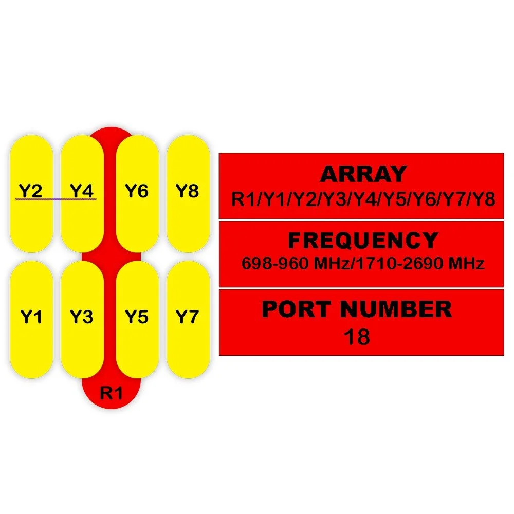
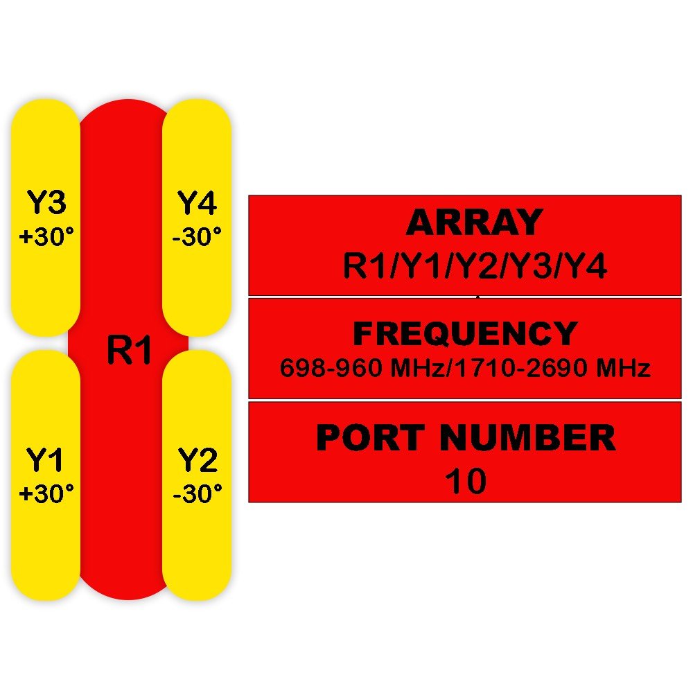
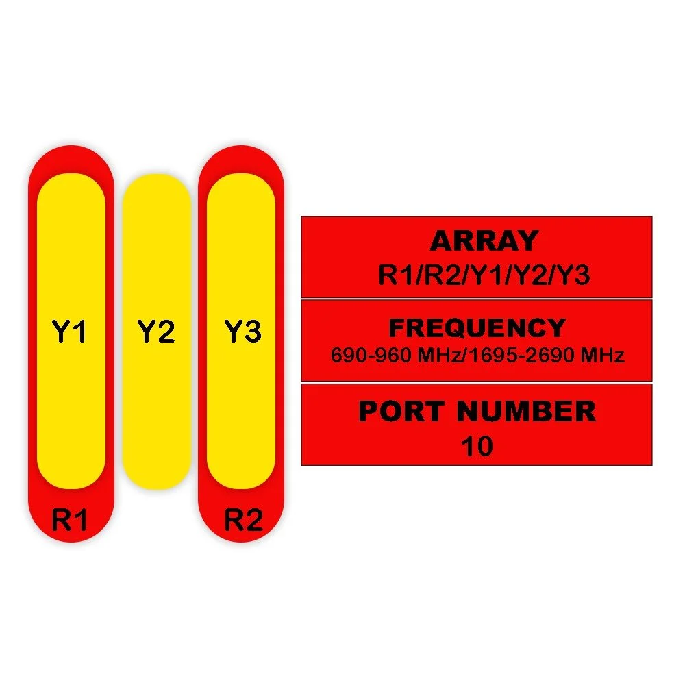
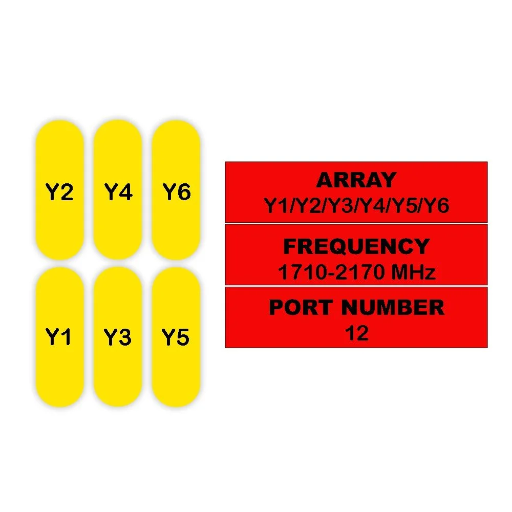
Y1 / Y2 / Y3
| Parameter | Sub Item | Unit | 1710-1880 | 1850-1990 | 1920-2170 | 2300-2500 | 2500-2690 |
|---|---|---|---|---|---|---|---|
| Frequency Range | MHz | 1710-2690 | |||||
| MHz | 1710-1880 | 1850-1990 | 1920-2170 | 2300-2500 | 2500-2690 | ||
| Polarization | --- | ±45° | |||||
| Gain | at Mid Tilt | dBi | 15.2 | 15.6 | 15.8 | 16.1 | 16.1 |
| Over All Tilts | dBi | 15.1 ± 0.6 | 15.5 ± 0.6 | 15.7 ± 0.6 | 16.0 ± 0.6 | 15.9 ± 0.6 | |
| Horizontal Beamwidth | degree | 67 ± 5 | 65 ± 5 | 64 ± 5 | 62 ± 5 | 60 ± 5 | |
| Vertical Beamwidth | degree | 9.7 ± 1.0 | 9.1 ± 0.9 | 8.5 ± 0.9 | 7.1 ± 0.7 | 6.6 ± 0.7 | |
| Electrical Downtilt (Adjustable) | degree | 2–12 | |||||
| First Upper Side Lobe Suppression | dB | > 15 | > 15 | > 15 | > 15 | > 15 | |
| Front-To-Back Ratio ±30° | dB | ≥ 23 | ≥ 23 | > 24 | ≥ 25 | ≥ 25 | |
| Cross Polar Discrimination | At Boresight | dB | > 18 | > 18 | > 18 | > 18 | > 18 |
| Over Sector | dB | > 8 | > 8 | > 8 | > 8 | > 8 | |
| Squint | degree | 3.5 | 3.5 | 3.5 | 3.5 | 3.5 | |
| Tracking | dB | 3 | 3 | 3 | 3 | 3 | |
| Isolation | Cross-Polar | dB | ≥ 25 | ||||
| Port-To-Port | dB | ≥ 25 | |||||
| Impedance | Ohm | 50 | |||||
| VSWR | --- | < 1.5 | |||||
| Return Loss | dB | > 14 | |||||
| PIM3 (2x43 dBm Carrier) | dBc | < -153 | |||||
| Lightning Protection | --- | DC Ground | |||||
| Maximum Avg Input Power per Port (50°C) | Watts | 200 | |||||
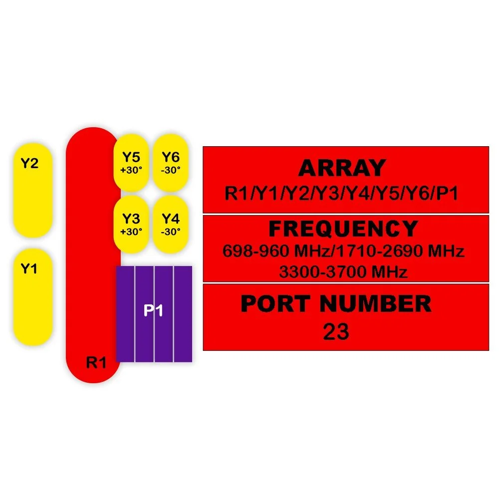
TDD LTE – P1
| Parameter | Sub Item | Unit | 2300–2690 MHz | 3300–3800 MHz |
|---|---|---|---|---|
| Frequency Range | MHz | 2300–3800 | ||
| MHz | 2300–2690 | 3300–3800 | ||
| Polarization | --- | ±45° | ||
| Electrical Downtilt | degree | 2–12 | ||
| Single Column Beam | Gain | dBi | 15.5 | 16.5 |
| Horizontal Beamwidth | degree | 90 | 70 | |
| Vertical Beamwidth (3 dB) | degree | 8.3 ± 0.8 | 6.2 ± 0.6 | |
| Cross-Polar Ratio at Boresight | dB | ≥ 16 | ≥ 16 | |
| Cross-Polar Ratio Over Sector | dB | 10 | 10 | |
| First Upper Side Lobe Suppression | dB | ≥ 15 | ≥ 15 | |
| Front-To-Back Ratio | dB | ≥ 25 | ≥ 25 | |
| 65° Broadcast Beam | Gain | dBi | 16.5 | 17.3 |
| Horizontal Beamwidth (3 dB) | degree | 65 | 65 | |
| Vertical Beamwidth (3 dB) | degree | 8.3 ± 0.8 | 6.2 ± 0.6 | |
| Cross-Polar Ratio at Boresight | dB | ≥ 16 | ≥ 16 | |
| Cross-Polar Ratio Over Sector | dB | 10 | 10 | |
| First Upper Side Lobe Suppression | dB | ≥ 15 | ≥ 15 | |
| Front-To-Back Ratio | dB | ≥ 25 | ≥ 25 | |
| Service Beam (0°) | Direct Beam Gain | dBi | 20 | 20.5 |
| 3 dB Horizontal Beamwidth | degree | 25 | 20 | |
| Cross Polar Ratio at Beam-Peak | dB | ≥ 18 | ≥ 18 | |
| Cross Polar Discrimination over 10 dB | dB | 11 | 11 | |
| Front-To-Back Ratio | dB | ≥ 30 | ≥ 30 | |
| ±30° Direct Beam Gain | dB | 18.5 | 19.0 | |
| Soft Split Multi-Beam | Gain | dBi | 19.0 | --- |
| Horizontal Beamwidth (3 dB) | degree | 31 | --- | |
| Vertical Beamwidth (3 dB) | degree | 8.3 ± 0.8 | --- | |
| First Upper Side Lobe Suppression | dB | 18 | --- | |
| Front-To-Back Ratio | dB | ≥ 30 | --- | |
| Cross Polar Ratio at Beam-Peak | dB | ≥ 18 | --- | |
| Cross Polar Ratio Over 10 dB | dB | 11 | --- | |
| Calibration & Electrical Parameters | Coupling Factor | dB | -26 ± 2 | |
| Max. Amplitude Tolerance | dB | 1 | ||
| Max. Phase Tolerance | degree | 9 | ||
| Ports VSWR | --- | 1.5 | ||
| Average Power Capacity | W | 75 | ||
| Isolation | Intraband | dB | ≥ 25 | |
| Interband | dB | ≥ 20 | ||
| Impedance | Ohm | 50 | ||
| Lightning Protection | --- | DC Ground | ||
| Category | Parameter | Specification |
|---|---|---|
| Protocols | Standards Compliance | Compliant to AISG v2.0 and 3GPP |
| Supply Voltage | Input Range | 10–30 V DC; Compliant to AISG 2.0 and 3GPP TS25.461 V6.0.0 |
| Power Consumption | Standby | < 2 W |
| Power Consumption | In Motion | < 10 W |
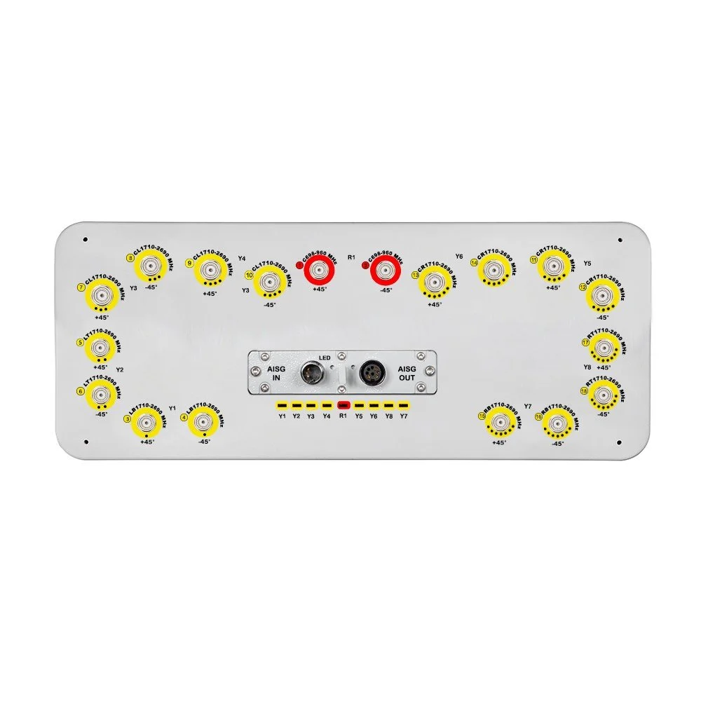
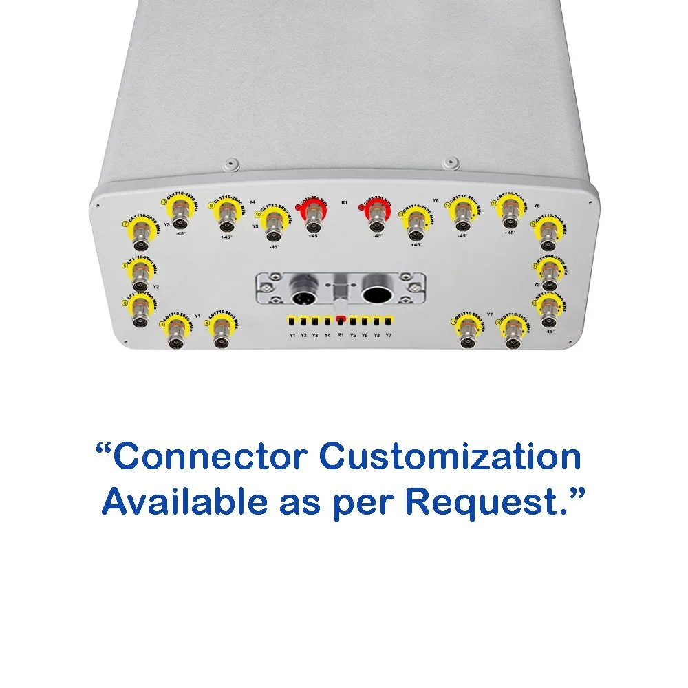
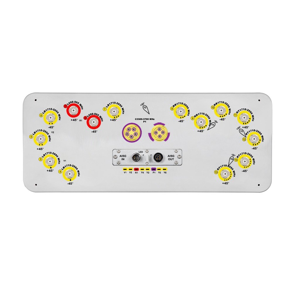
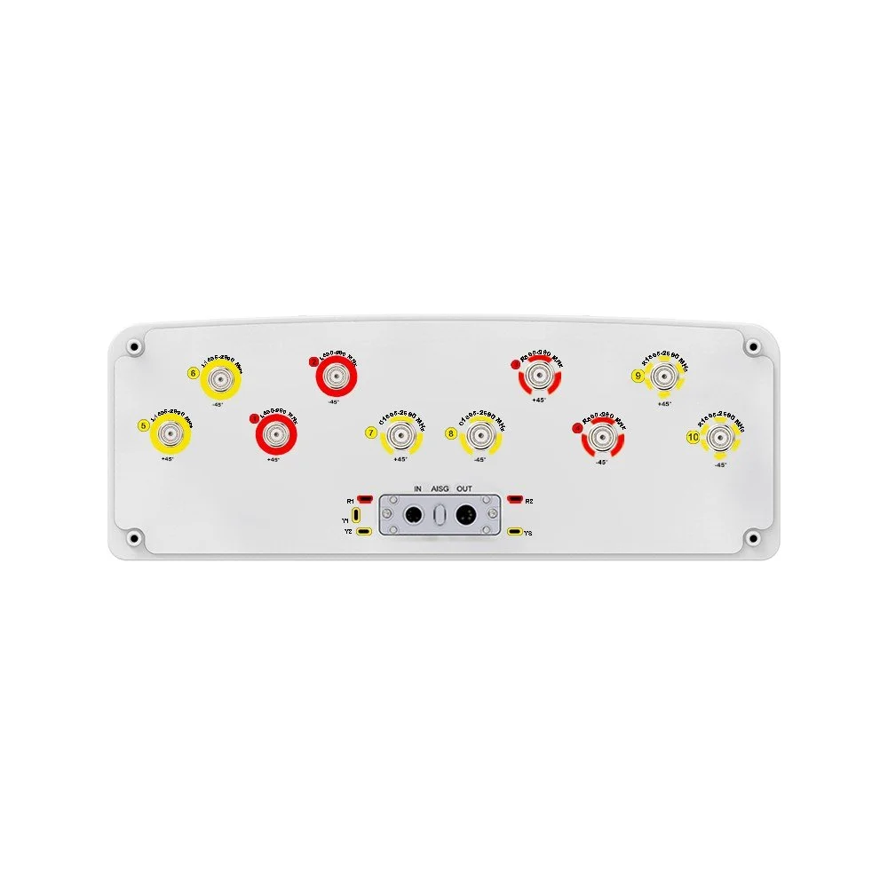
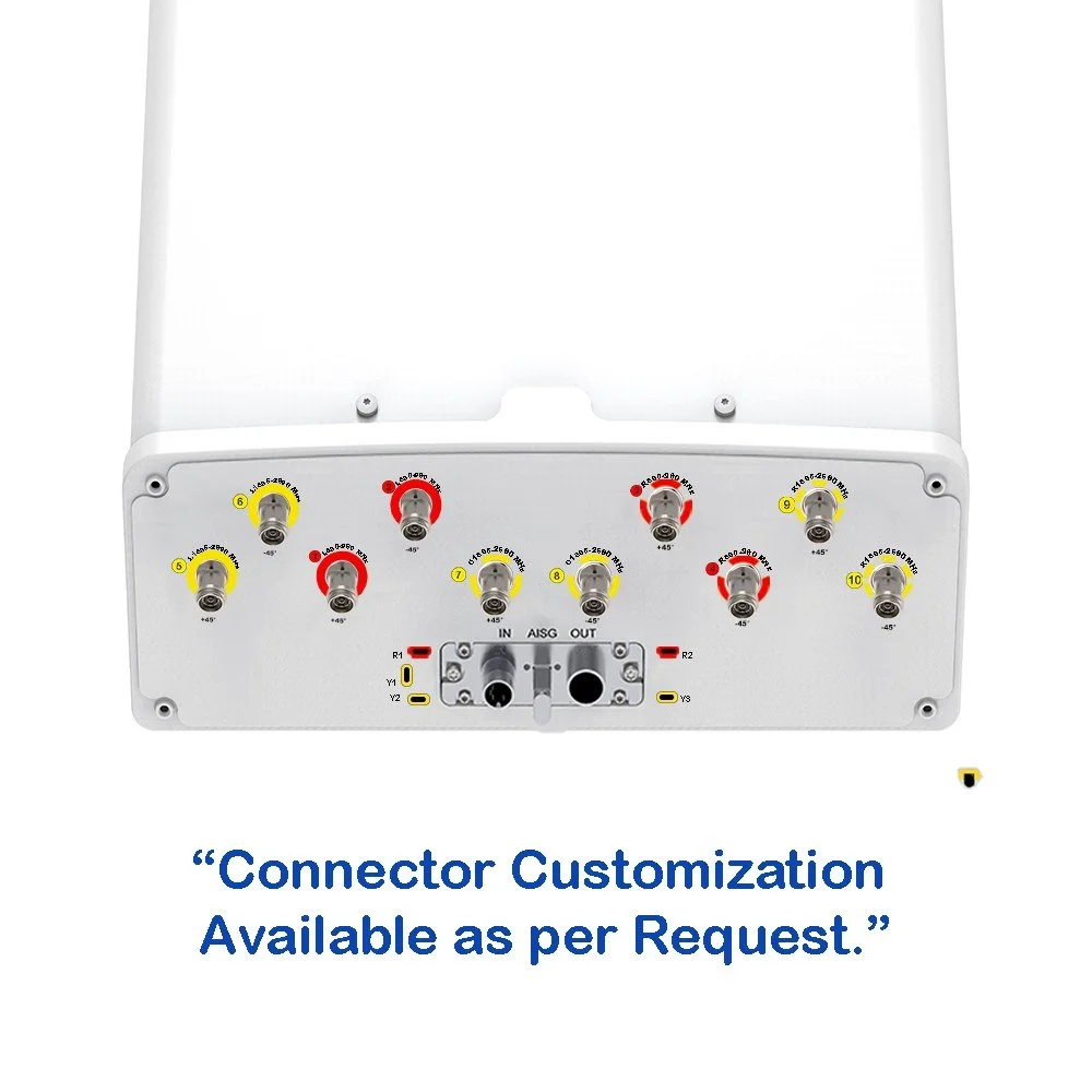
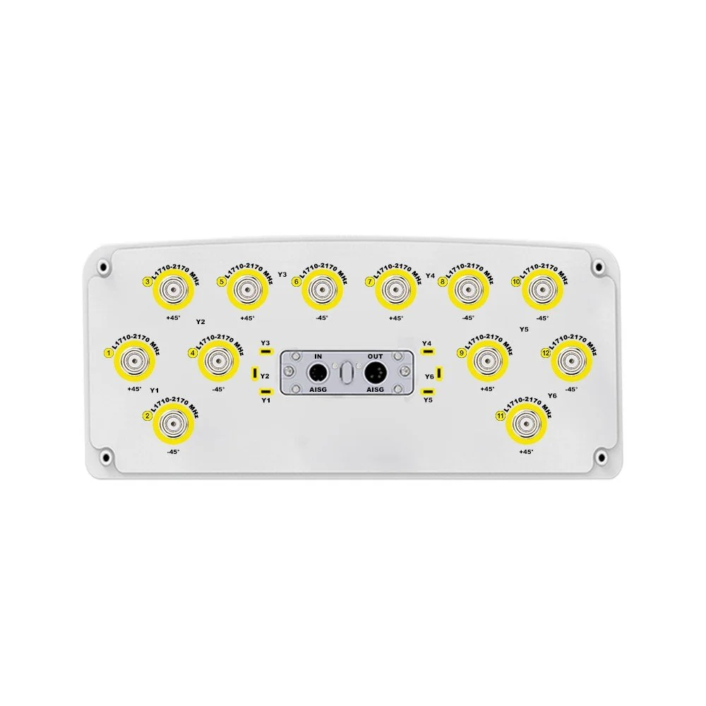
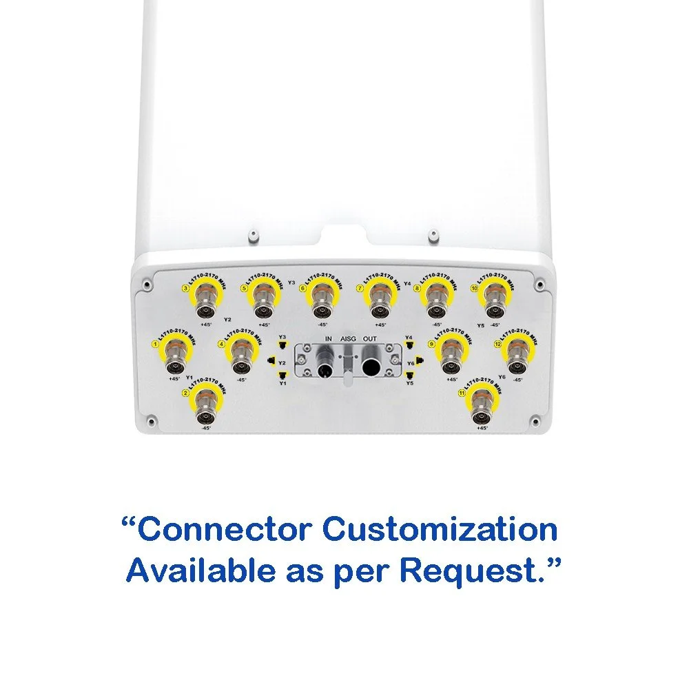
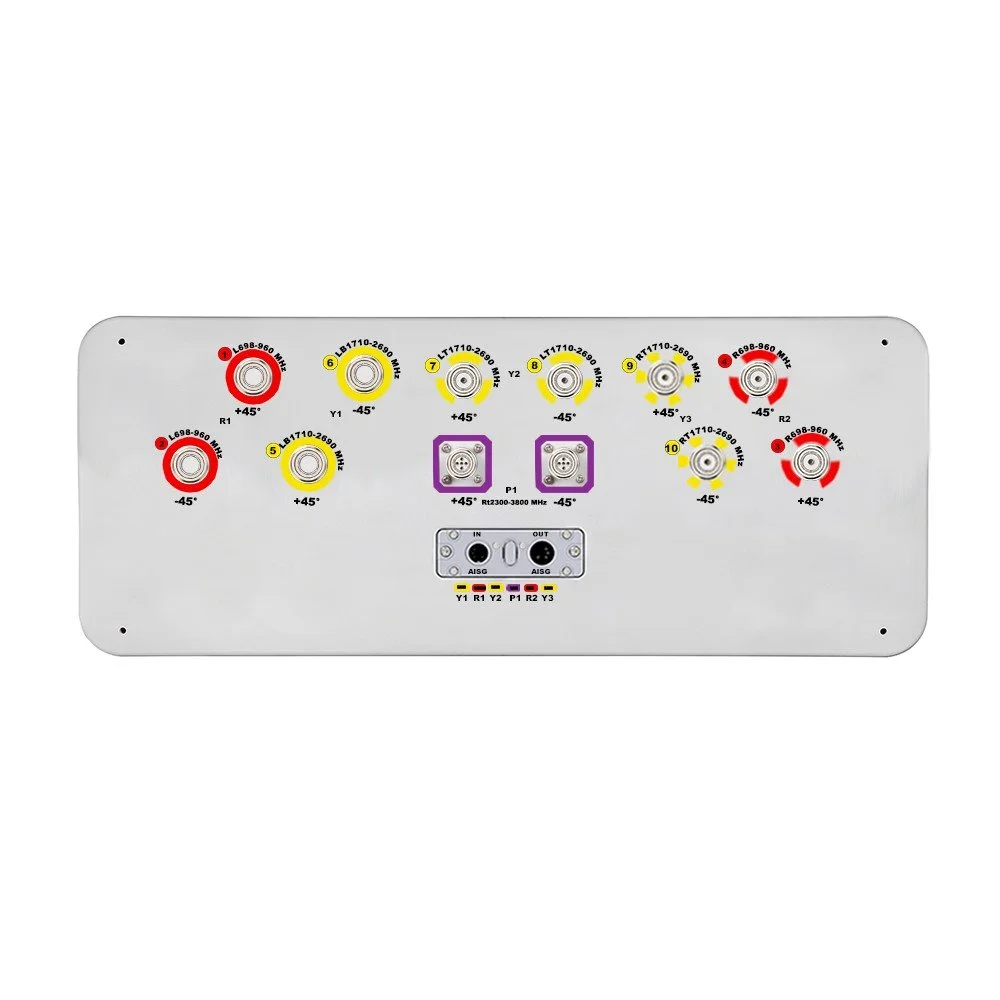
| Connectors | Type | 2 × 8 Pin Circular Connector according to IEC 60130-9; AISG Daisy Chain (In: Male, Out: Female) |
| Connectors | Pin Assignment | Pin 3: RS485B; Pin 5: RS485A; Pin 6: 10–30 V; Pin 7: DC Return |
| Connectors | Connector Details | Female Connector: 8 Pins; Male Connector: 4 Pins |
| Lightning Protection | IEC 61000-4-5 Current Pulse Profile |
Line to Ground: 8/20 µs @ 8 kA ≥ ±5 Repetitions Line to Line: 8/20 µs @ 3 kA ≥ ±5 Repetitions |
| Safety Standard | Compliance | Compliant to EN 60950 / UL 60950 / RoHS / CE |
| Parameter | Unit | Specification |
|---|---|---|
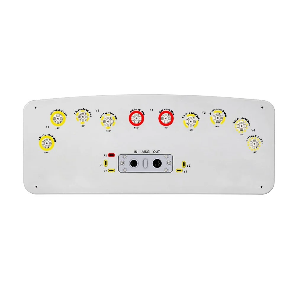
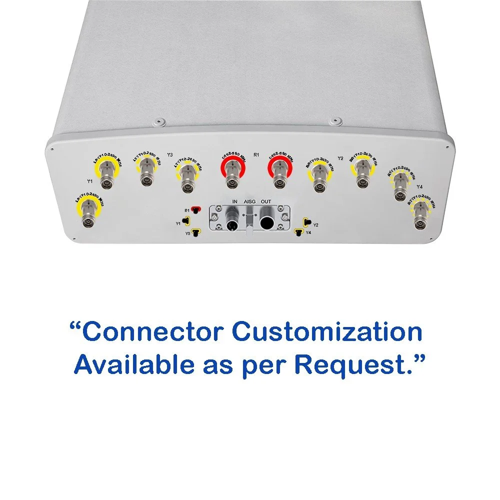
| Connector Type | — | (10×) 4.3/10 Female + (2×) Cluster |
| Connector Position | — | Bottom |
| Electrical Tilt Control | — |
FDD: Integrated RET, Each Band Individually Adjustable TDD: Integrated RET, Single Internal RET Control for All Four Antenna Arrays |
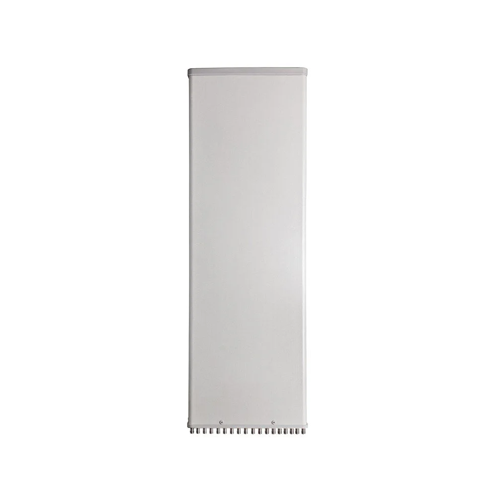
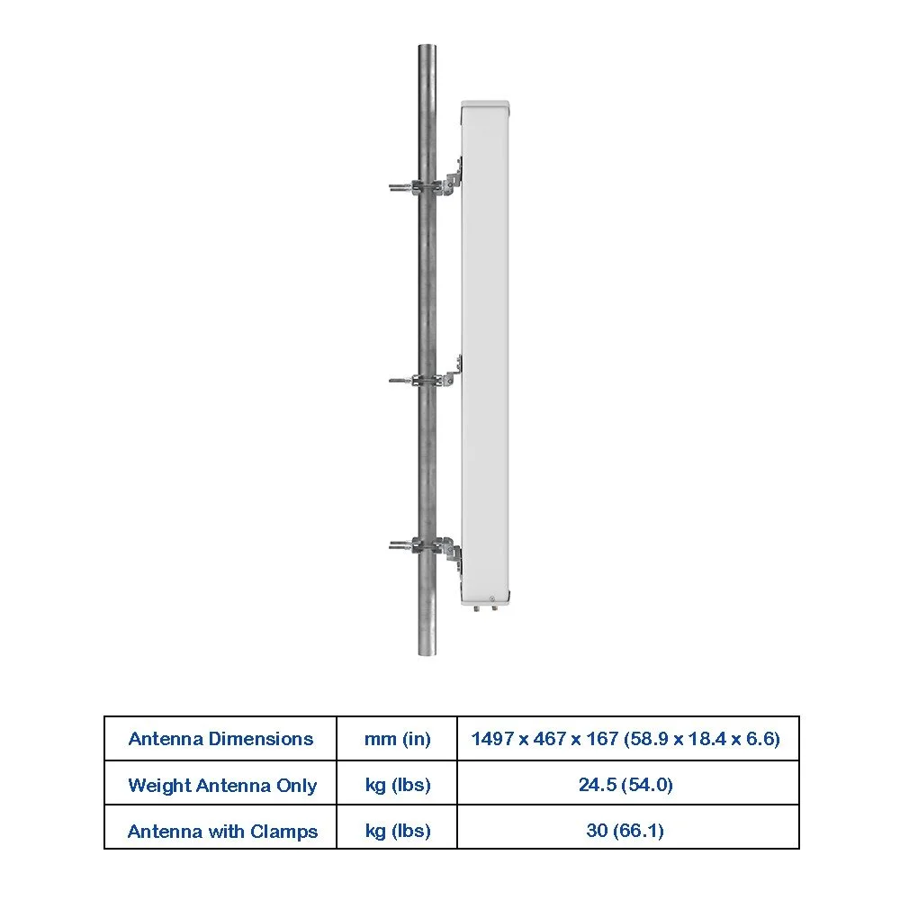
| Radome Material | — | Fiberglass |
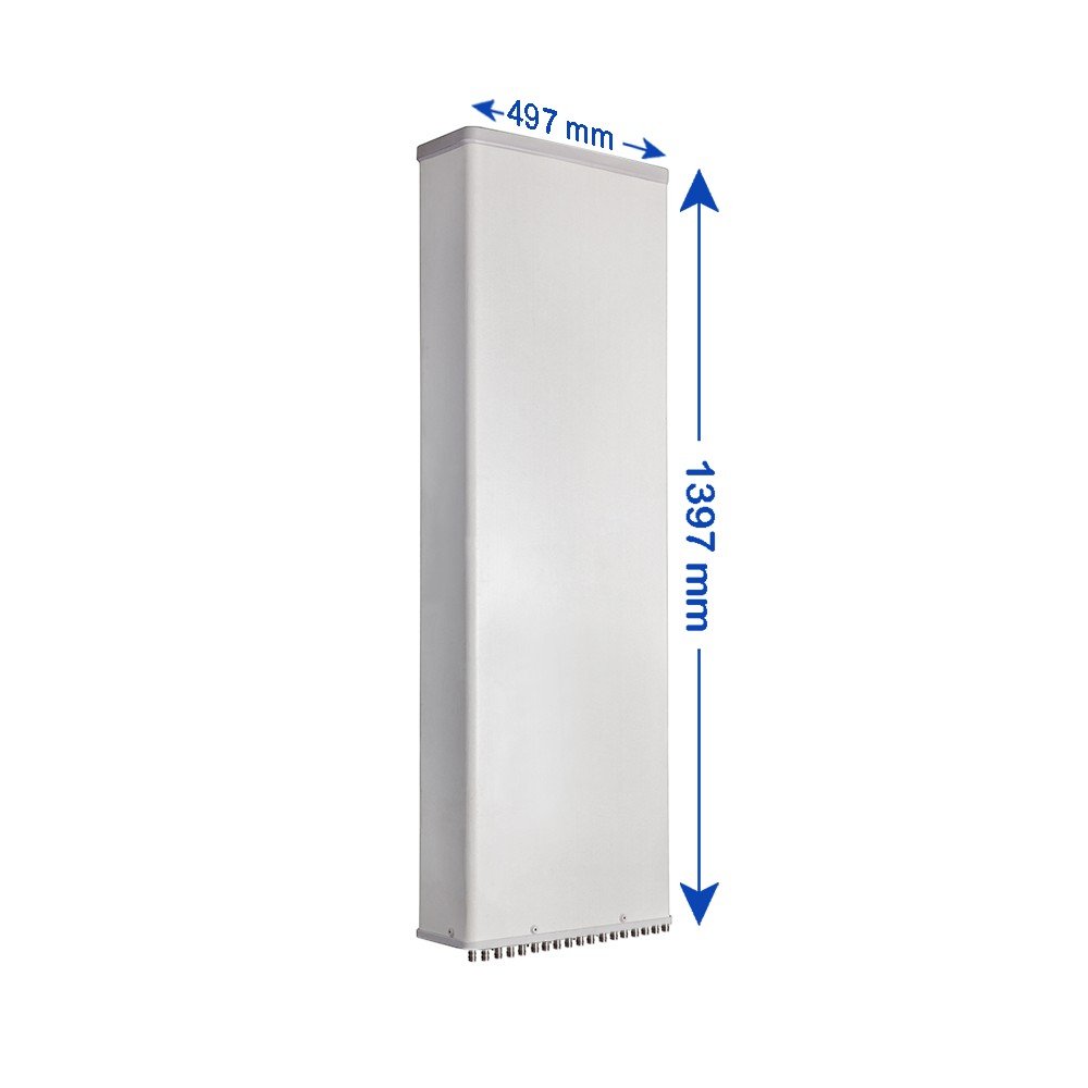
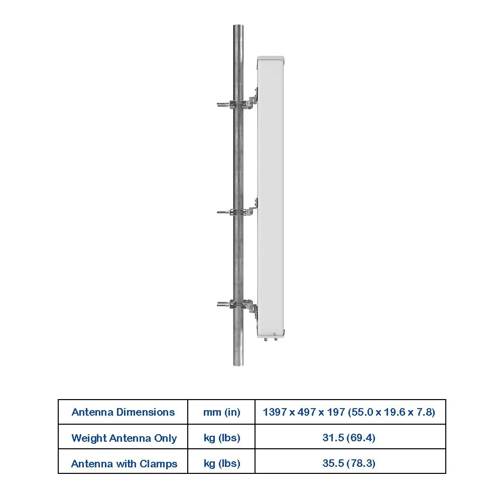
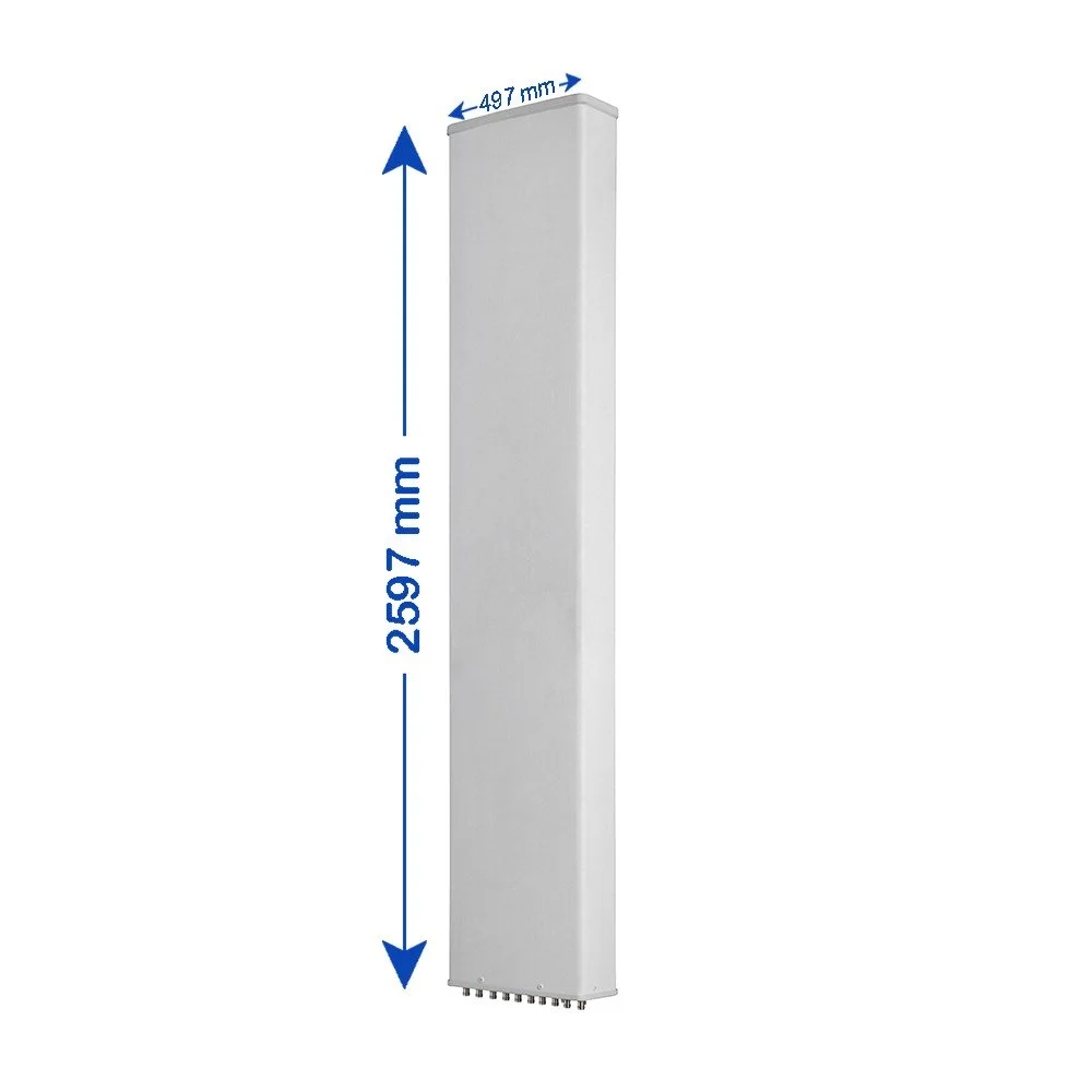
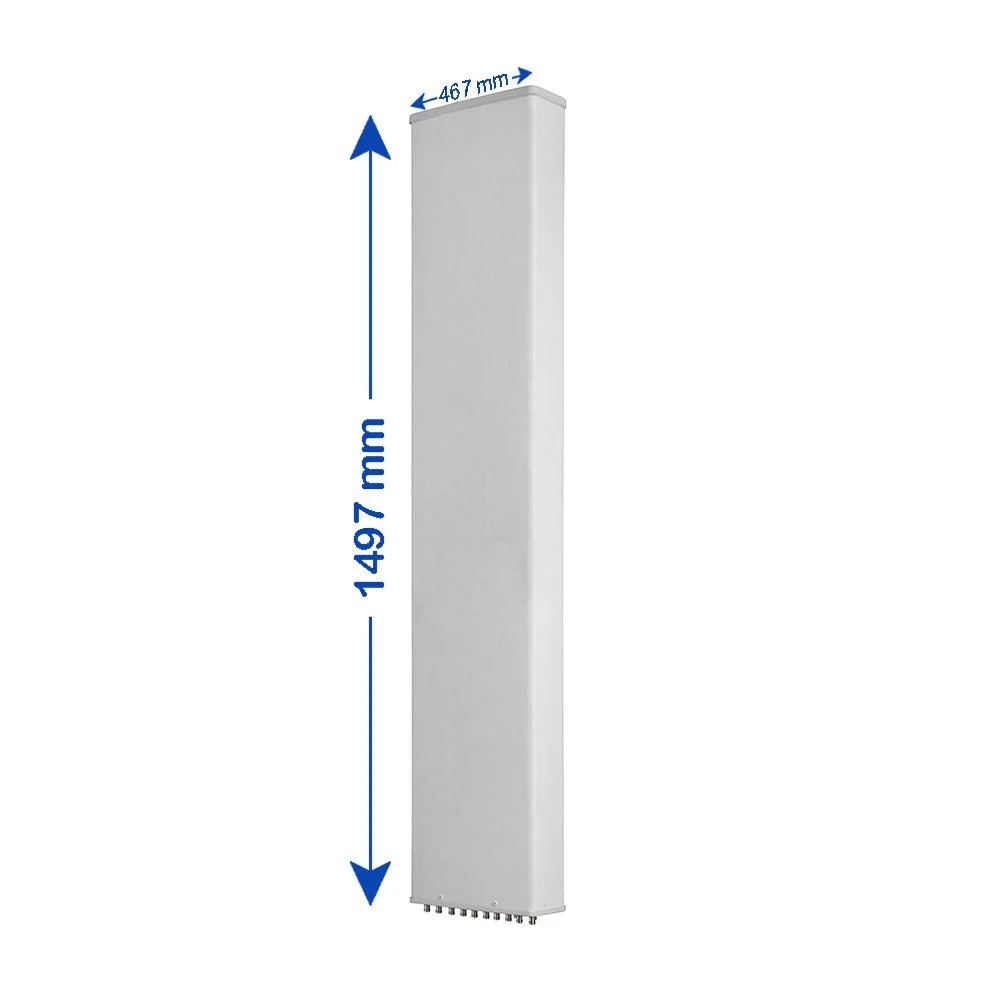
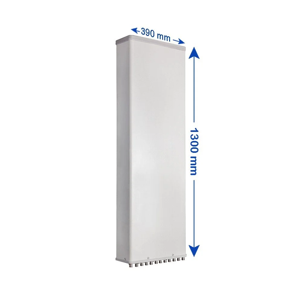
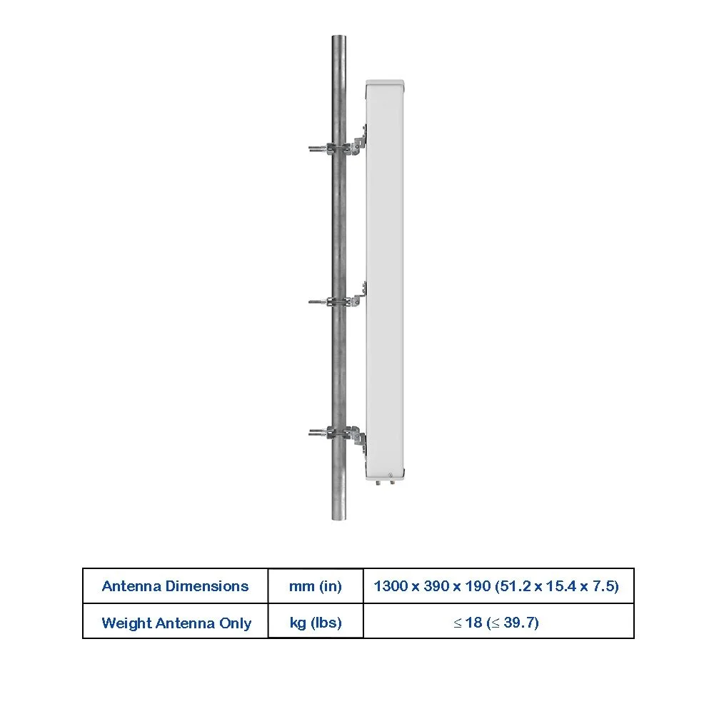
| Antenna Dimensions (H × W × D) | mm (in) | 1997 × 497 × 197 (78.6 × 19.6 × 7.8) |
| Antenna Weight (Antenna Only) | kg (lbs) | 37.5 (82.7) |
| Antenna Weight (with Clamps) | kg (lbs) | 43 (94.8) |
| Maximum Wind Speed | km/h (mph) | 200 (124.3) |
| Wind Load at 150 km/h (Frontal) | N (lbf) | 915 (205.7) |
| Wind Load at 150 km/h (Rear) | N (lbf) | 1025 (230.4) |
| Wind Load at 150 km/h (Lateral) | N (lbf) | 450 (101.2) |
| Operating Temperature | °C (°F) | -40 to +60 (-40 to 140) |