 Image 1 of 6
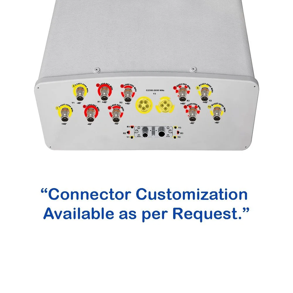 Image 2 of 6
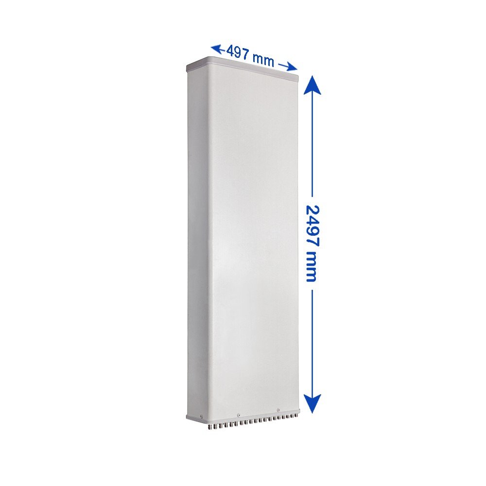 Image 3 of 6
 Image 4 of 6
 Image 5 of 6
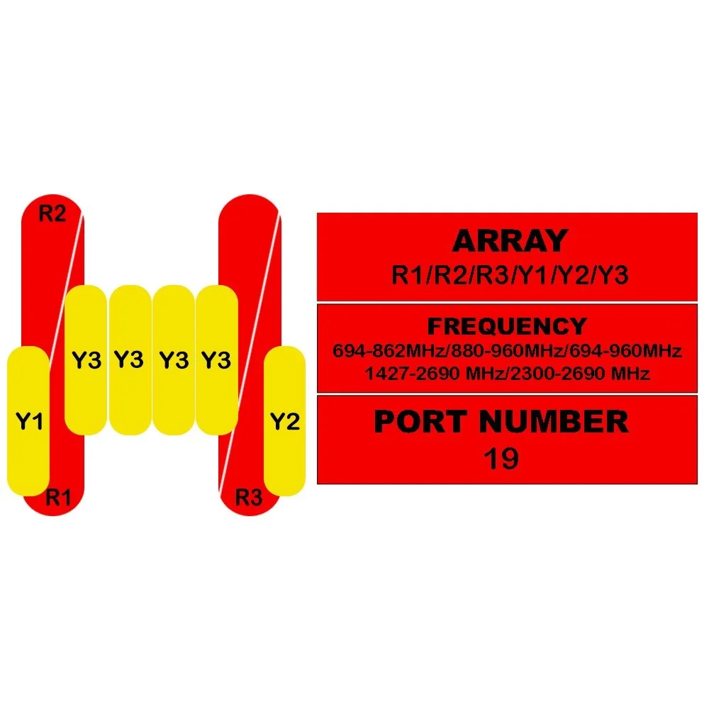 Image 6 of 6
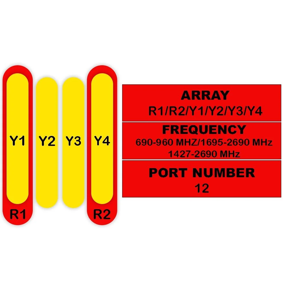
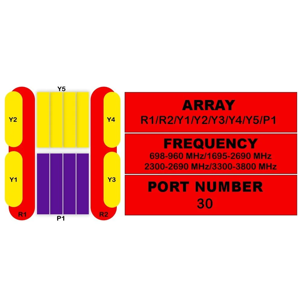
| Electrical Specifications | |||||||
|---|---|---|---|---|---|---|---|
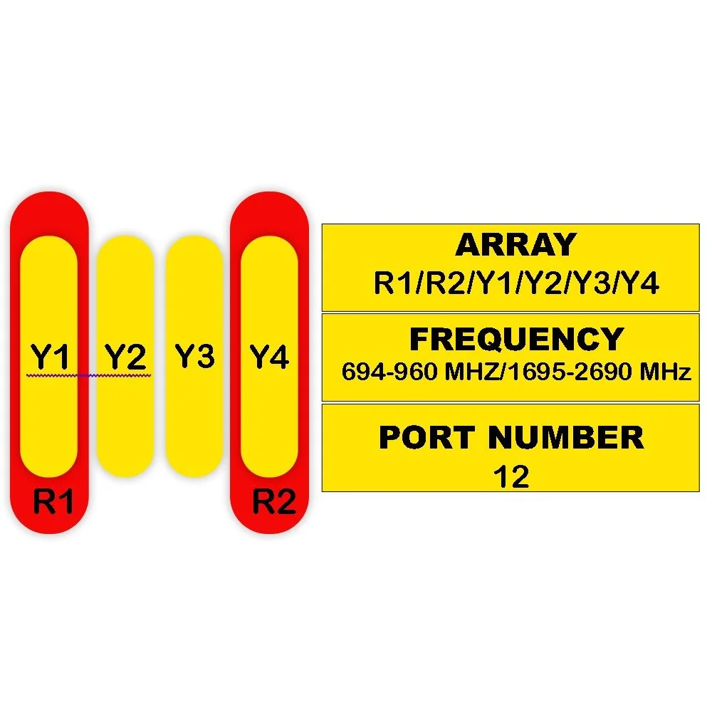
| Parameter | Unit | R1 | R2 | R3 | R1 (Alt) | R2 (Alt) | R3 (Alt) |
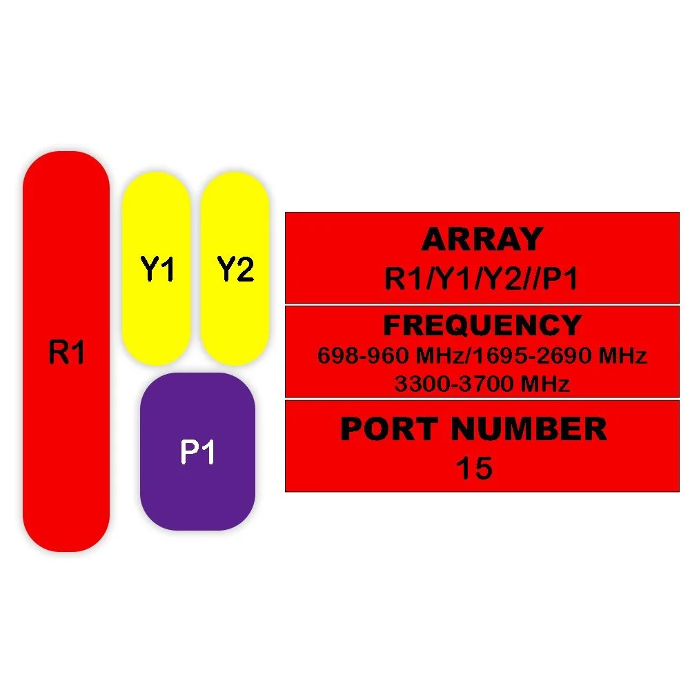
| Frequency Range | MHz | 694–862 | 880–960 | 694–960 | 694–806 | 790–894 | 880–960 |
| Polarization | — | ±45° | ±45° | ±45° | ±45° | ±45° | ±45° |
| Gain (at Mid Tilt) | dBi | 15.8 | 16.2 | 16.6 | 16.2 | 16.6 | 17.0 |
| Gain (Over All Tilts) | dBi | 15.2 ± 0.6 | 15.6 ± 0.6 | 16.0 ± 0.6 | 15.6 ± 0.6 | 16.0 ± 0.6 | 16.4 ± 0.6 |
| Horizontal Beamwidth | degree | 68 ± 6.5 | 64 ± 6.5 | 61 ± 6.5 | 68 ± 6.5 | 64 ± 6.5 | 61 ± 6.5 |
| Vertical Beamwidth | degree | 8.8 ± 0.8 | 7.8 ± 0.6 | 7.2 ± 0.7 | 8.8 ± 0.8 | 7.8 ± 0.6 | 7.2 ± 0.7 |
| Electrical Downtilt (Continuous) | degree | 2–12 | 2–12 | 2–12 | 2–12 | 2–12 | 2–12 |
| Tilt Accuracy | degree | < 1 | < 1 | < 1 | < 1 | < 1 | < 1 |
| Upper Side Lobe Suppression (First Upper Lobe) | dB | > 15 | > 15 | > 15 | > 15 | > 15 | > 15 |
| Upper Side Lobe Suppression (Peak to 20°) | dB | > 14 | > 14 | > 14 | > 14 | > 14 | > 14 |
| Front-To-Back Ratio ±30° | dB | > 23 | > 24 | > 25 | > 23 | > 24 | > 25 |
| Cross Polar Discrimination (At Boresight) | dB | > 17 | > 17 | > 18 | > 17 | > 17 | > 18 |
| Cross Polar Discrimination (Over Sector) | dB | > 9 | > 7 | > 6 | > 9 | > 7 | > 6 |
| Isolation (Cross-Polar) | dB | > 26 | > 26 | > 26 | > 26 | > 26 | > 26 |
| Isolation (Port-To-Port) | dB | > 25 | > 25 | > 25 | > 25 | > 25 | > 25 |
| Impedance | Ohm | 50 | 50 | 50 | 50 | 50 | 50 |
| VSWR | — | < 1.5 | < 1.5 | < 1.5 | < 1.5 | < 1.5 | < 1.5 |
| Return Loss | dB | > 14 | > 14 | > 14 | > 14 | > 14 | > 14 |
| PIM3 (2×43 dBm Carrier) | dBc | < -150 | < -150 | < -150 | < -150 | < -150 | < -150 |
| Lightning Protection | — | DC Ground | DC Ground | DC Ground | DC Ground | DC Ground | DC Ground |
| Max Avg Input Power per Port @ 50°C | Watts | 200 | 200 | 250 | 200 | 200 | 250 |
| Electrical Specifications – Y1 / Y2 | ||||||
|---|---|---|---|---|---|---|
| Parameter | Unit | 1427–1518 | 1695–1920 | 1920–2170 | 2300–2400 | 2490–2690 |
| Frequency Range | MHz | 1427–2690 | ||||
| Polarization | — | ±45° | ||||
| Gain (at Mid Tilt) | dBi | 16.0 | 16.9 | 17.7 | 18.0 | 18.0 |
| Gain (Over All Tilts) | dBi | 15.4 ± 0.6 | 16.4 ± 0.5 | 17.2 ± 0.5 | 17.4 ± 0.6 | 17.4 ± 0.6 |
| Horizontal Beamwidth | degree | 73 ± 6.5 | 70 ± 5.5 | 66 ± 6.0 | 65 ± 8.0 | 63 ± 9.0 |
| Vertical Beamwidth | degree | 7.8 ± 0.6 | 6.0 ± 0.8 | 5.4 ± 0.6 | 4.9 ± 0.5 | 4.4 ± 0.6 |
| Electrical Downtilt (Continuous) | degree | 2–12 | ||||
| Tilt Accuracy | degree | < 1 | < 1 | < 1 | < 1 | < 1 |
| Upper Side Lobe Suppression (First Upper Lobe) | dB | > 15 | > 15 | > 15 | > 15 | > 15 |
| Upper Side Lobe Suppression (Peak to 20°) | dB | > 14 | > 14 | > 14 | > 14 | > 14 |
| Front-To-Back Ratio ±30° | dB | > 22 | > 24 | > 25 | > 25 | > 24 |
| Cross Polar Discrimination (At Boresight) | dB | > 16 | > 16 | > 16 | > 16 | > 16 |
| Cross Polar Discrimination (Over Sector) | dB | > 6 | > 6 | > 5 | > 3 | > 2 |
| Isolation (Cross-Polar) | dB | > 25 | ||||
| Isolation (Port-To-Port) | dB | > 25 | ||||
| Impedance | Ohm | 50 | ||||
| VSWR | — | < 1.5 | ||||
| Return Loss | dB | > 14 | ||||
| PIM3 (2×43 dBm Carrier) | dBc | < -150 | ||||
| Lightning Protection | — | DC Ground | ||||
| Max Avg Input Power per Port @ 50°C | Watts | 200 | ||||
| Electrical Specifications – Y3 | ||||
|---|---|---|---|---|
| Parameter | Unit | 2300–2400 MHz | 2490–2690 MHz | Notes |
| Frequency Range | MHz | 2300–2690 | Band Split: 2300–2400 / 2490–2690 | |
| Polarization | — | ±45° | ||
| Electrical Downtilt (Continuous) | degree | 2–12 | ||
| Beamforming Electrical Properties – Single Column Beam | ||||
| Gain | dBi | 15.6 ± 1 | 16.1 ± 1 | |
| Horizontal Beamwidth | degree | 85 ± 10 | 80 ± 10 | |
| Vertical Beamwidth | degree | 5.4 ± 0.5 | 5.0 ± 0.5 | |
| Cross-Polar Discrimination (Boresight) | dB | ≥ 16 | ≥ 16 | |
| First Upper Side Lobe Suppression | dB | ≥ 15 | ≥ 15 | |
| Front-To-Back Ratio (Co-Pol, ±30°) | dB | ≥ 28 | ≥ 28 | |
| Broadcast Beam (65°) | ||||
| Gain | dBi | 16.0 ± 1 | 17.1 ± 1 | |
| Horizontal Beamwidth | degree | 65 | 65 | |
| Vertical Beamwidth | degree | 5.4 ± 0.5 | 5.0 ± 0.5 | |
| Cross-Polar Discrimination (Boresight) | dB | ≥ 16 | ≥ 16 | |
| First Upper Side Lobe Suppression | dB | ≥ 15 | ≥ 15 | |
| Front-To-Back Ratio | dB | ≥ 28 | ≥ 28 | |
| Service Beam (0°) | ||||
| Direct Beam Gain (0°) | dBi | 21.1 ± 1 | 21.1 ± 1 | |
| ±30° Direct Beam Gain | dBi | 19.5 ± 1 | 19.5 ± 1 | |
| Direct Beam Horizontal Beamwidth | degree | 23 ± 3 | 22 ± 3 | |
| Direct Beam Cross-Polar Ratio (0°) | dB | ≥ 20 | ≥ 20 | |
| Direct Beam Azimuth Side Lobe Suppression | dB | ≥ 12 | ≥ 12 | |
| Direct Beam Front-To-Back Ratio | dB | ≥ 30 | ≥ 30 | |
| Multi-Beam | ||||
| Gain | dBi | 19.6 ± 1 | 20.1 ± 1 | |
| Soft Split Electrical Properties | ||||
| Horizontal Beamwidth | degree | 31 ± 3 | 29 ± 3 | |
| Vertical 3 dB Beamwidth | degree | 5.4 ± 0.5 | 5.0 ± 0.5 | |
| First Upper Side Lobe Suppression | dB | ≥ 17 | ≥ 17 | |
| Front-To-Back Ratio | dB | ≥ 28 | ≥ 28 | |
| Calibration & Electrical Parameters | ||||
| Coupling Factor (Calibration to Each Port) | dB | -26 ± 2 | ||
| Max Amplitude Tolerance (Calibration to Ports) | dB | ≤ 0.9 | ||
| Max Phase Tolerance (Calibration to Ports) | degree | ≤ 7 | ||
| Isolation | ||||
| Co-Polar Isolation Between Ports | dB | ≥ 23 | ||
| Cross-Polar Isolation Between Ports | dB | ≥ 25 | ||
| VSWR | — | < 1.5 | ||
| Return Loss | dB | > 14 | ||
| PIM3 (2×43 dBm Carrier) | dBc | < -150 | ||
| Lightning Protection | — | DC Ground | ||
| Max Avg Input Power per RF Port | W | 150 | ||
| Integrated RET Specifications | |
|---|---|
| Parameter | Specification |
| Protocols | Compliant to AISG v2.0 and 3GPP |
| Supply Voltage Range | 10–30 V DC; Compliant to AISG2.0 and 3GPP TS25.461 V6.0.0 |
| Power Consumption – Standby | < 2 W |
| Power Consumption – In Motion | < 10 W |
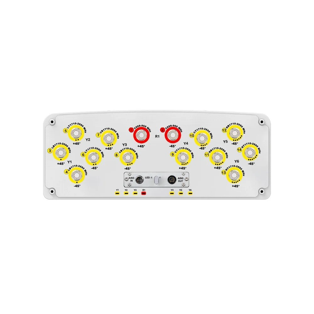
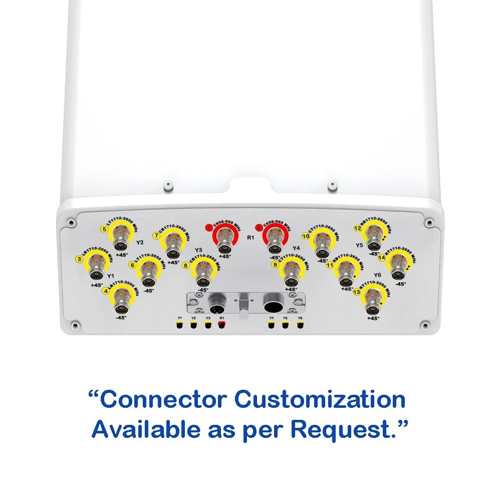
| Connectors |
2 × 8 Pin Circle Connector according to IEC 60130-9 and AISG Daisy Chain In: Male; Daisy Chain Out: Female Pin3: RS485B; Pin5: RS485A; Pin6: 10–30 V; Pin7: DC Return Female Connector: 8 PINs; Male Connector: 4 PINs |
| Hardware Interfaces | RS485 and Power |
| Adjustment Time | ≤ 90 sec (typical, depending on antenna type) |
| Adjustment Cycles | > 20,000 |
| Torque Maximum | ≥ 160 mN•m (@ 30 RPM) |
| Lightning Protection Rating |
IEC 61000-4-5 Current Pulse Profile Line to Ground: 8/20 µs @ 8 kA ≥ ±5 Repetitions Line to Line: 8/20 µs @ 3 kA ≥ ±5 Repetitions |
| Remote Control | Can be managed from OMC, BTS / Node B |
| Daisy Chaining Method | Ready for daisy-chaining |
| Safety Standard | Compliant to EN 60950 / UL 60950 / RoHS, CE |
| Housing Material / Color | Aluminum / Grey |
| Operating Temperature | -40° to +70° C (-40° to +158° F) |
| Storage Temperature | -55° to +75° C (-67° to +167° F) |
| Humidity | Up to 95% |
| IP Rating | IP65 |
| Weight | ≤ 500 g |
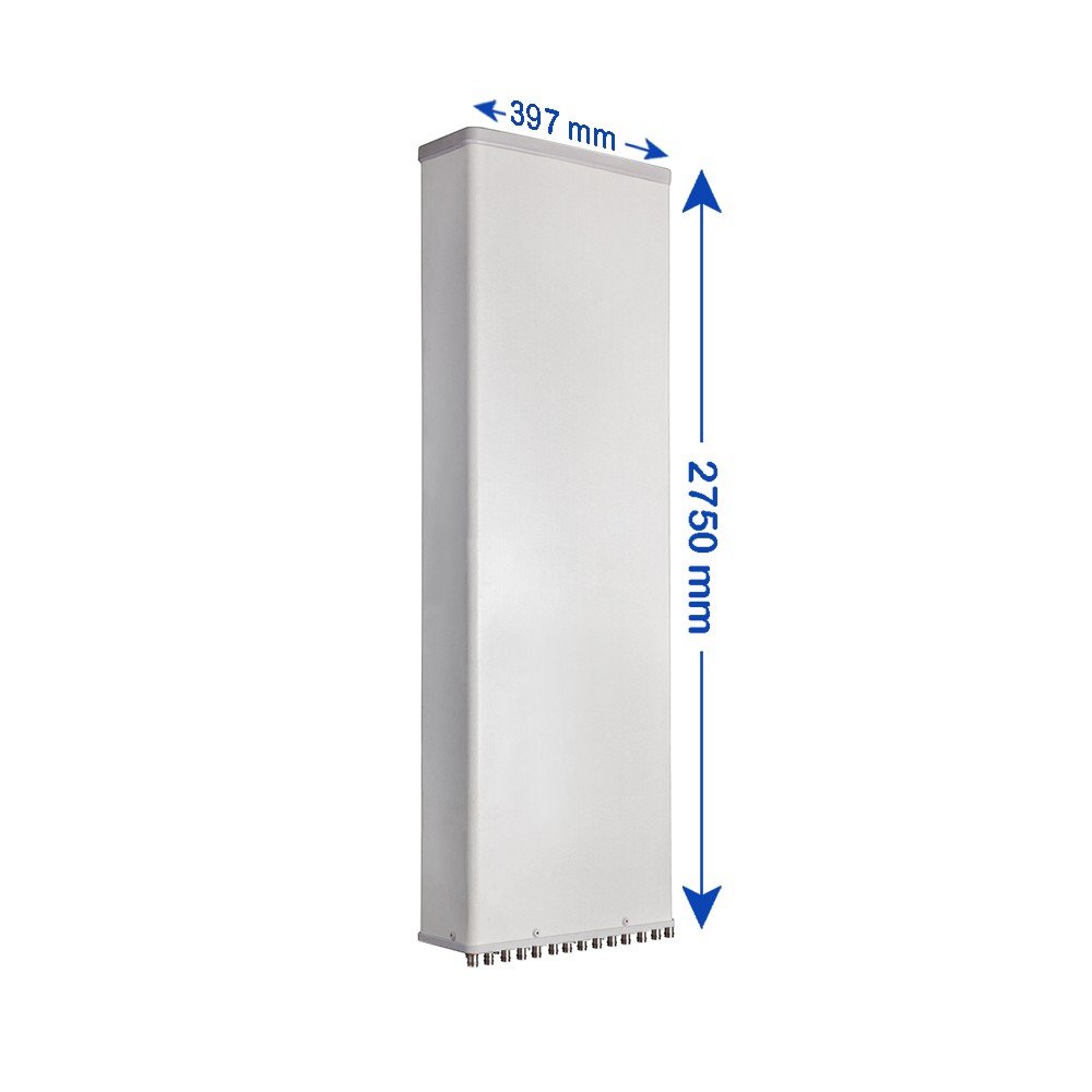
Mechanical Specifications
| Parameter | Sub Category | Unit | Specification |
|---|---|---|---|
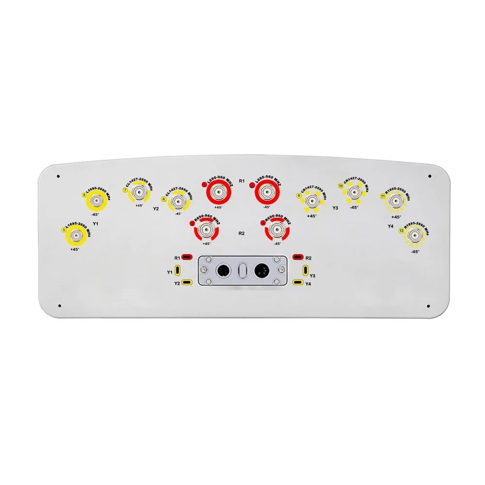
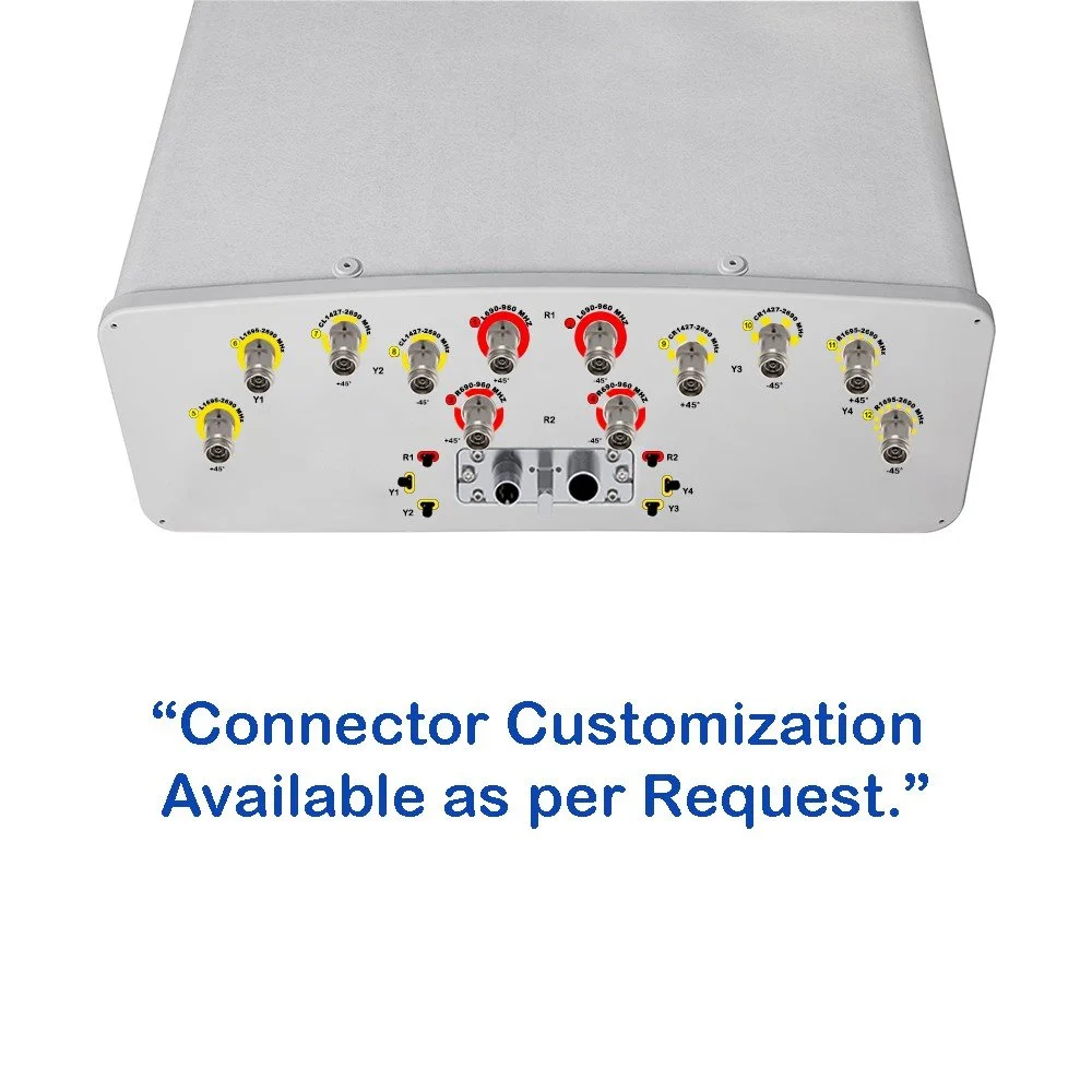
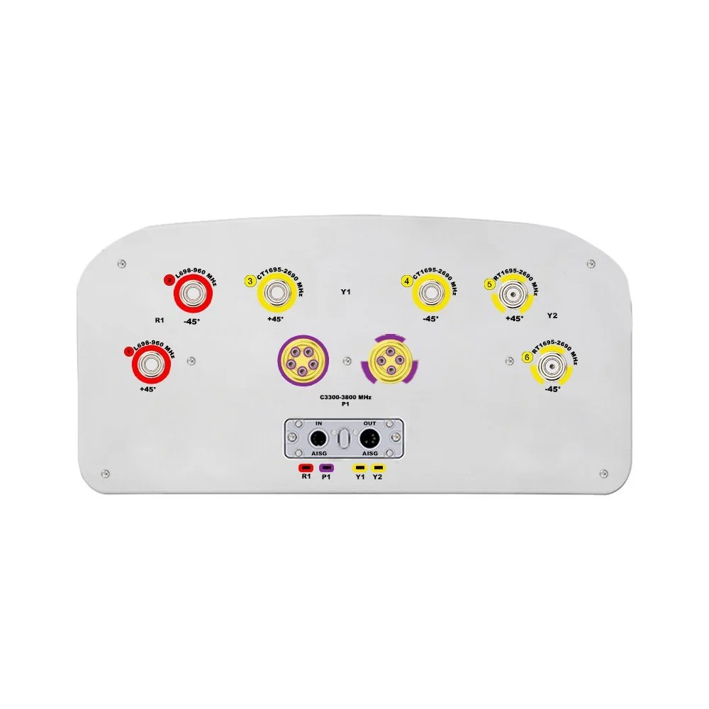
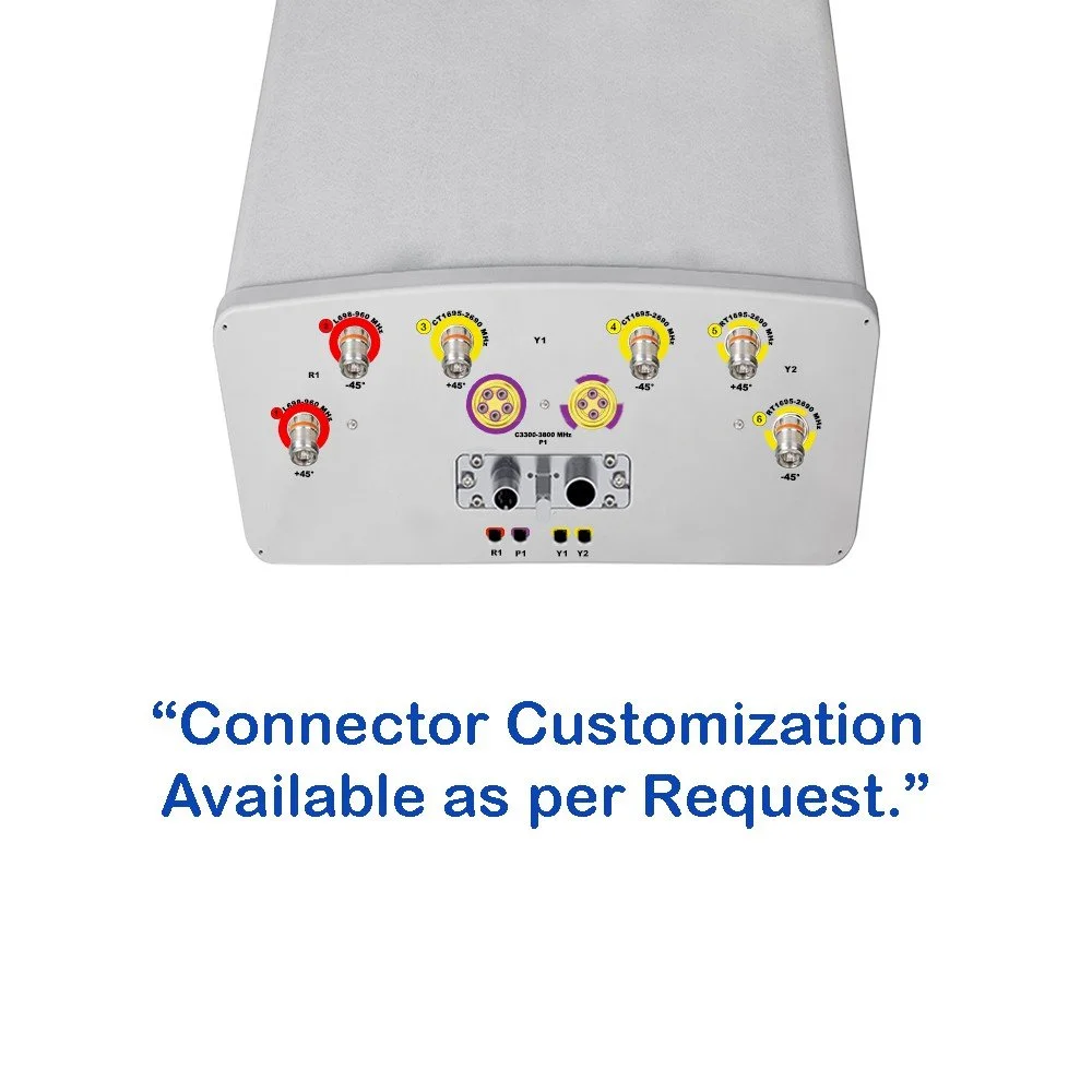
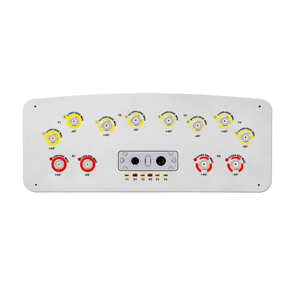
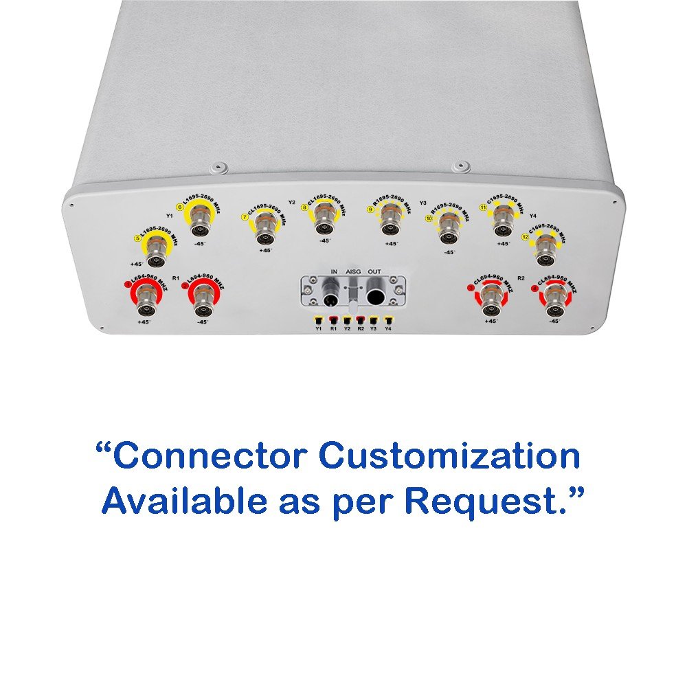
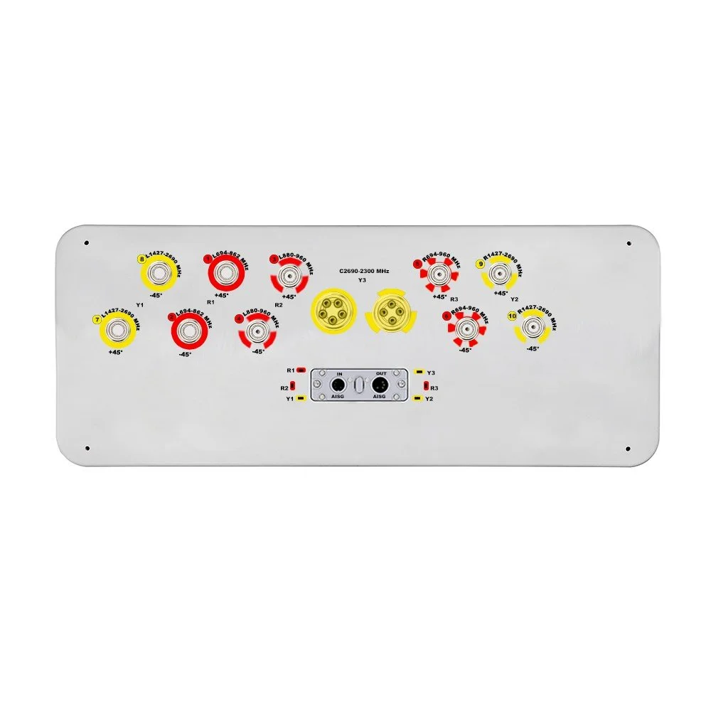
| Connector Type | --- | --- | (10x) 4.3/10 Female and (1x) MQ5 Male & (1x) MQ4 Male |
| Connector Position | --- | --- | Bottom |
| Electrical Tilt Control | --- | --- | Integrated RET |
| Radome Material | --- | --- | Fiberglass |
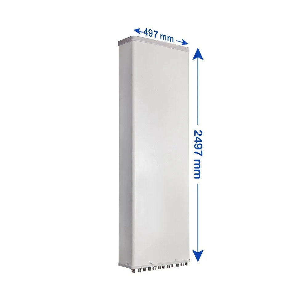
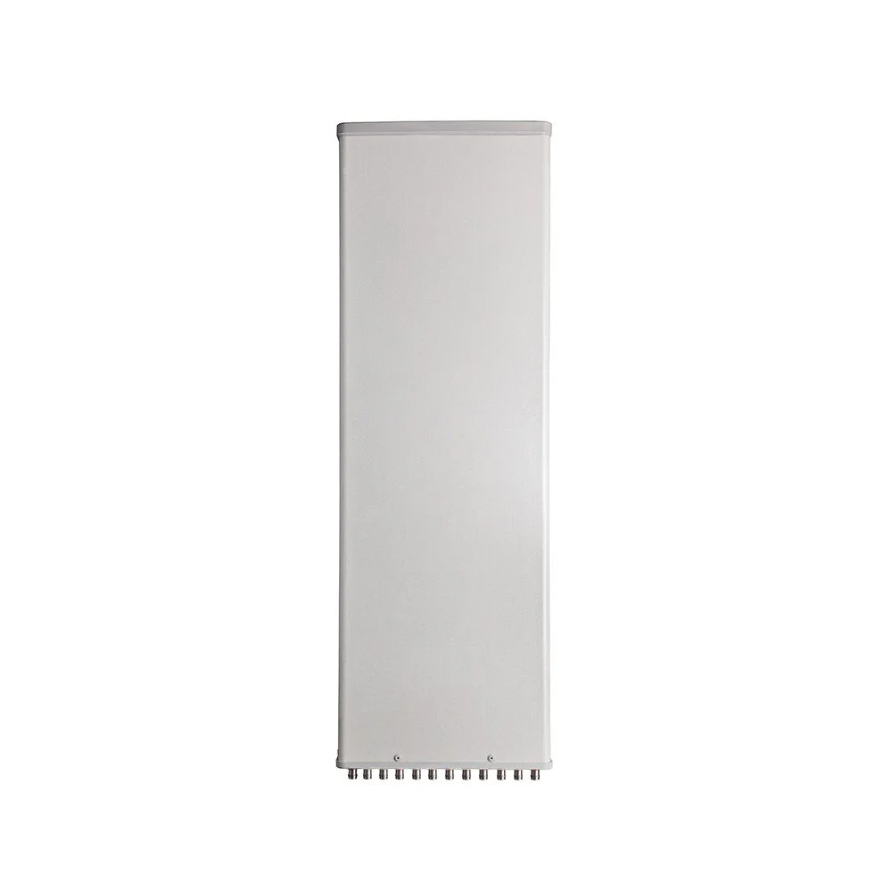
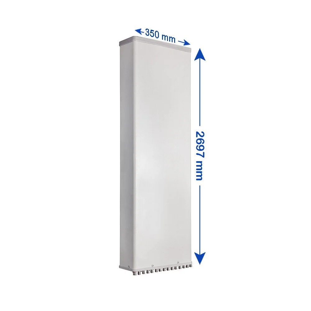
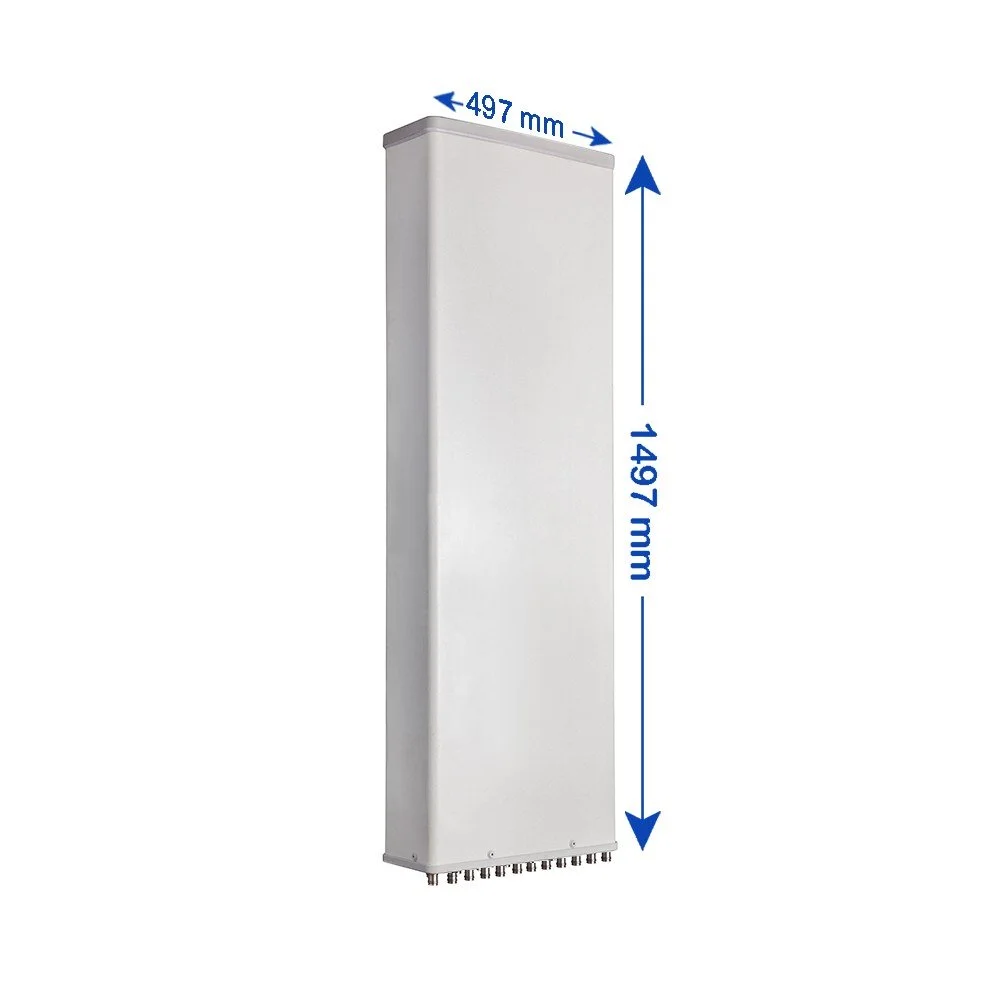
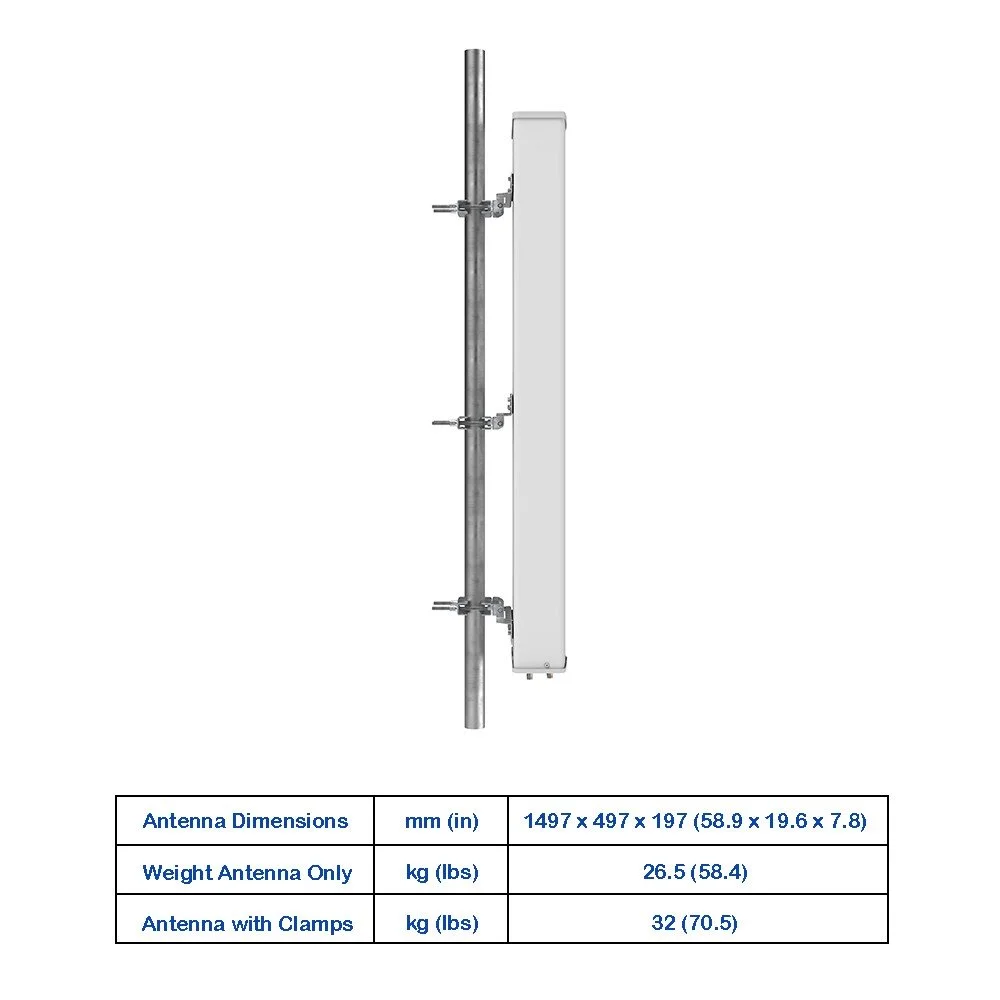
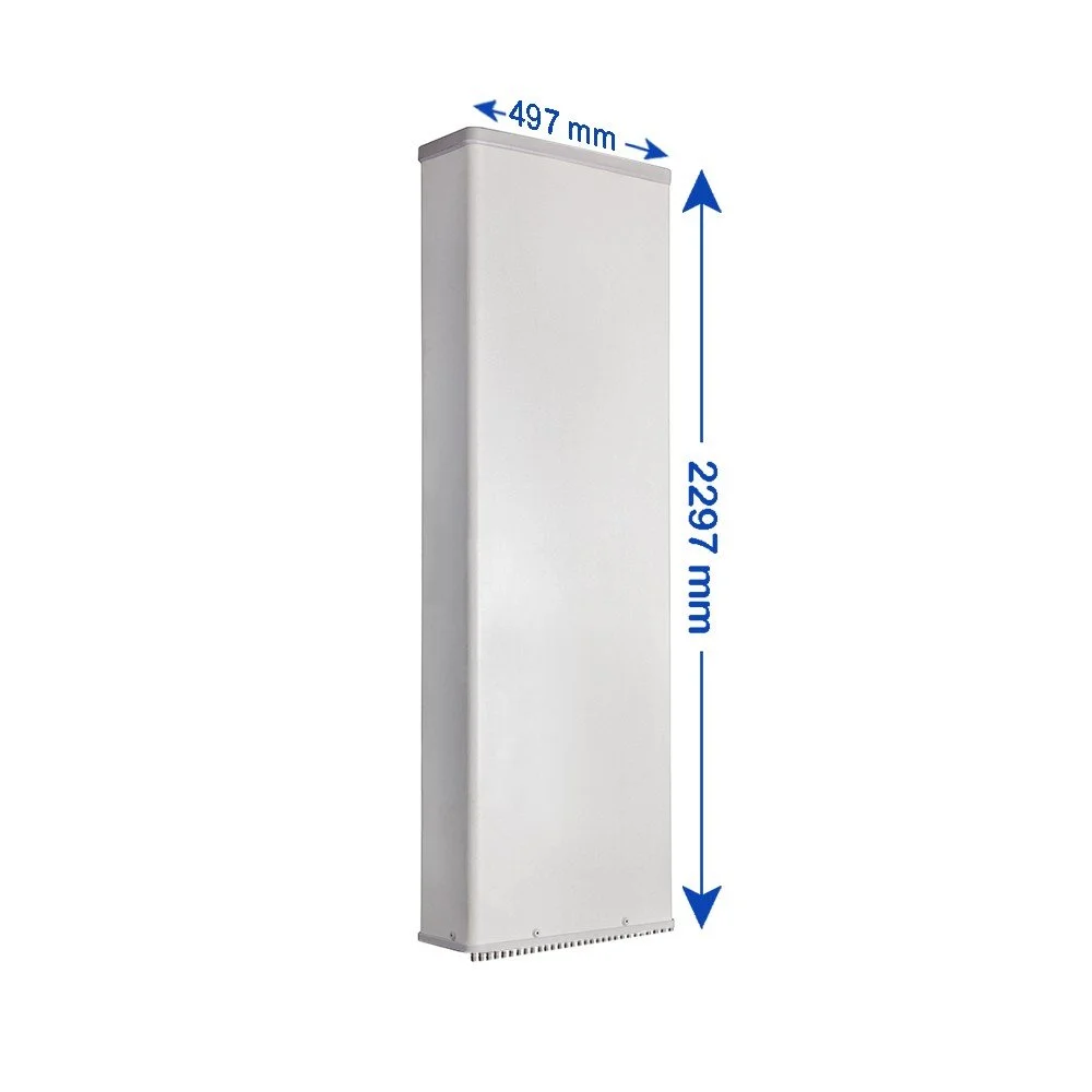
| Antenna Dimensions (H × W × D) | --- | mm (in) | 2497 × 497 × 197 (98.3 × 19.6 × 7.8) |
| Antenna Weight | Antenna Only | kg (lbs) | 52 (114.6) |
| With Clamps | kg (lbs) | 59.5 (131.2) | |
| Maximum Wind Speed | --- | km/h (mph) | 200 (124.3) |
| Wind Load at 150 km/h | Frontal | N (lbf) | 1145 (257.4) |
| Rear | N (lbf) | 1280 (287.8) | |
| Lateral | N (lbf) | 560 (125.9) | |
| Operating Temperature | --- | °C (°F) | -40 to +60 (-40 to 140) |