 Image 1 of 6
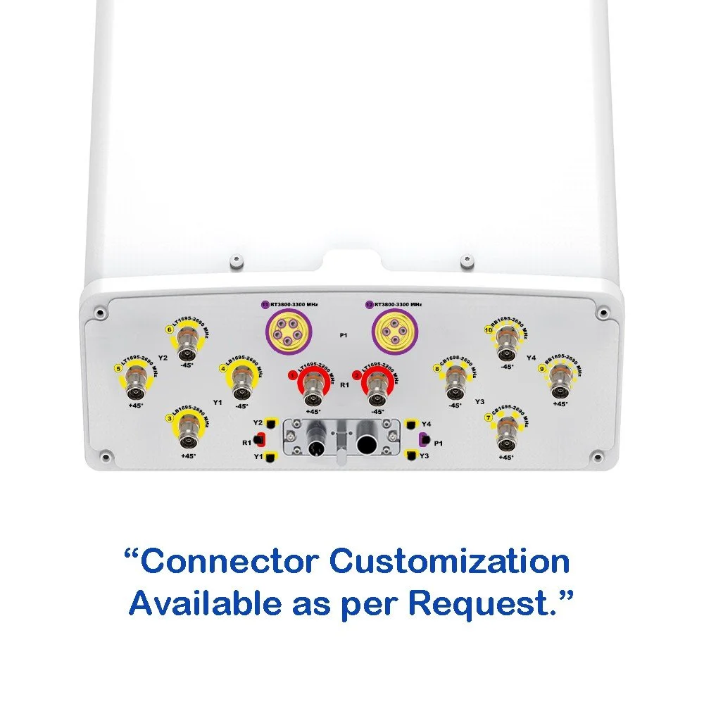 Image 2 of 6
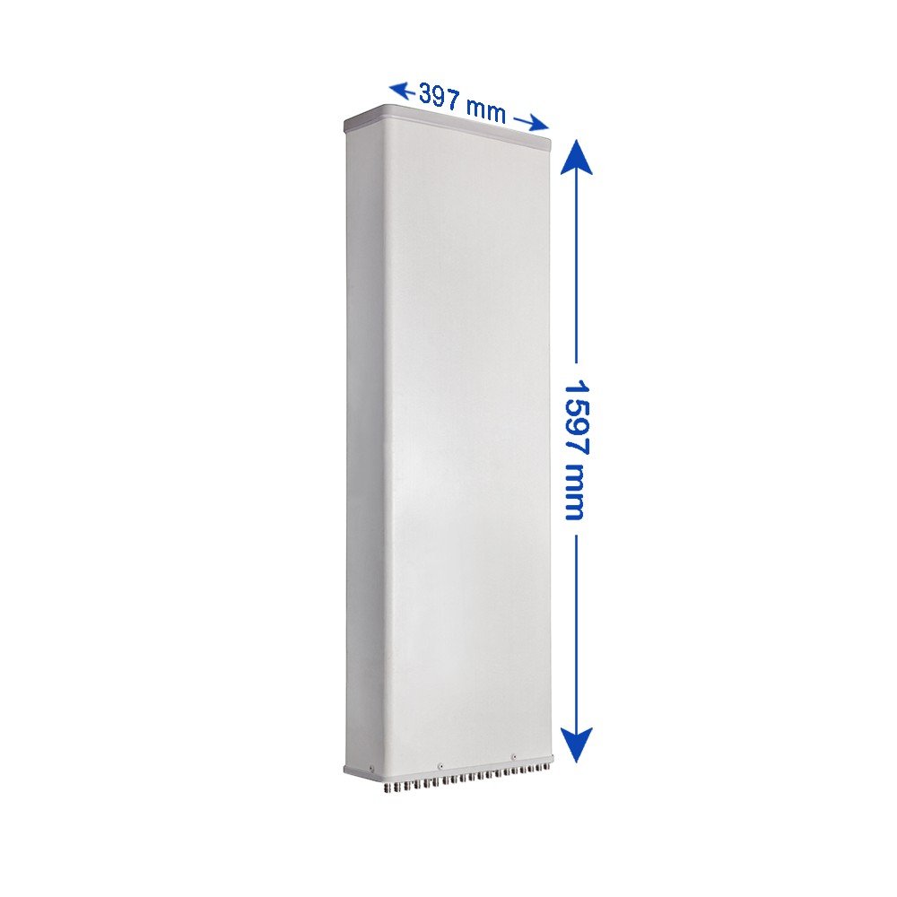 Image 3 of 6
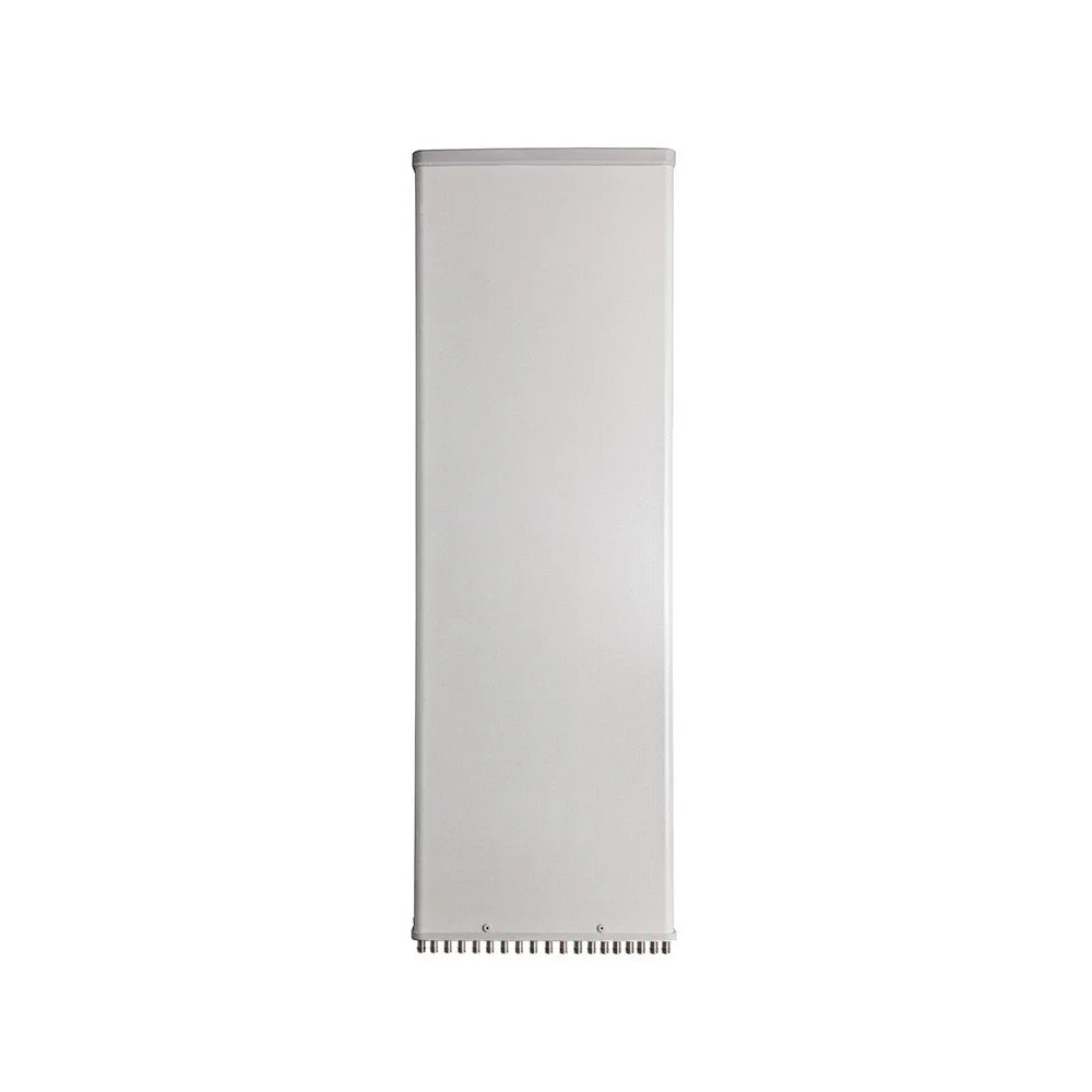 Image 4 of 6
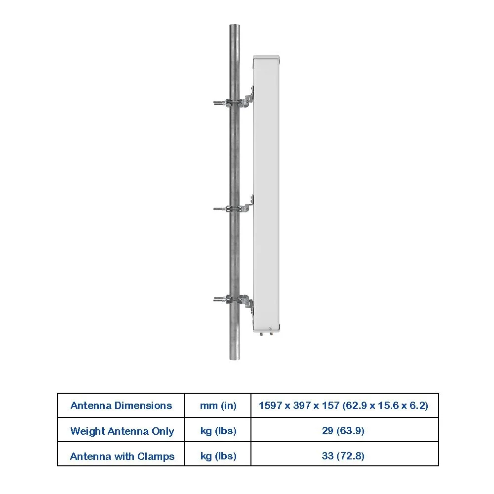 Image 5 of 6
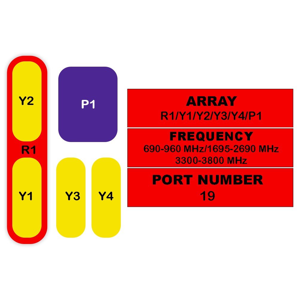 Image 6 of 6
Electrical Specifications
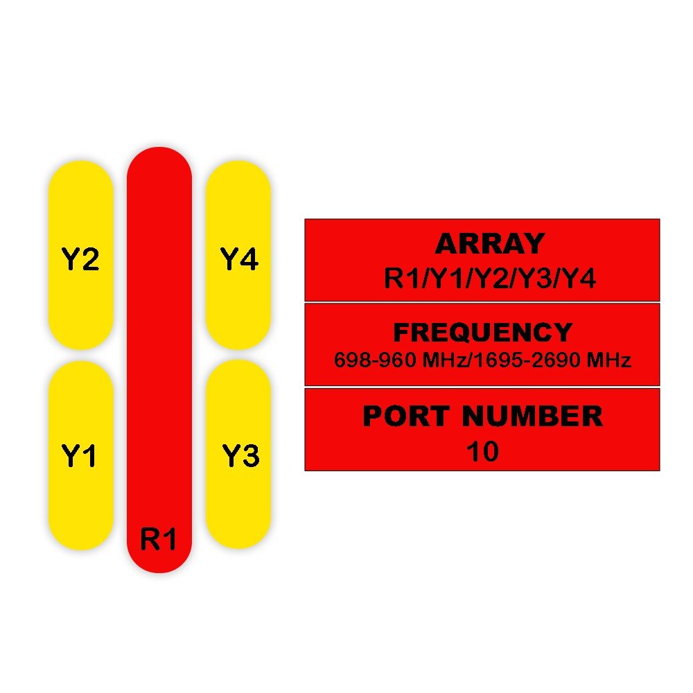
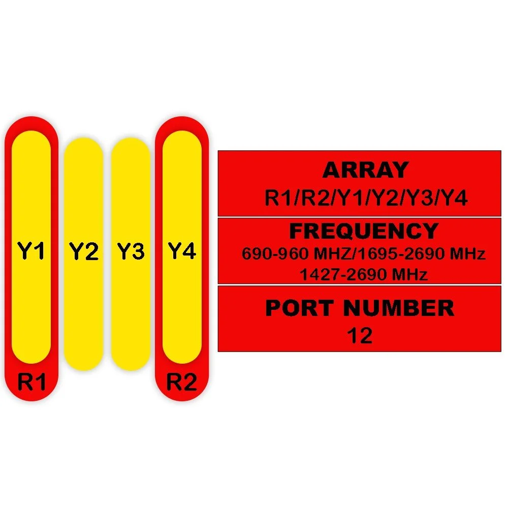
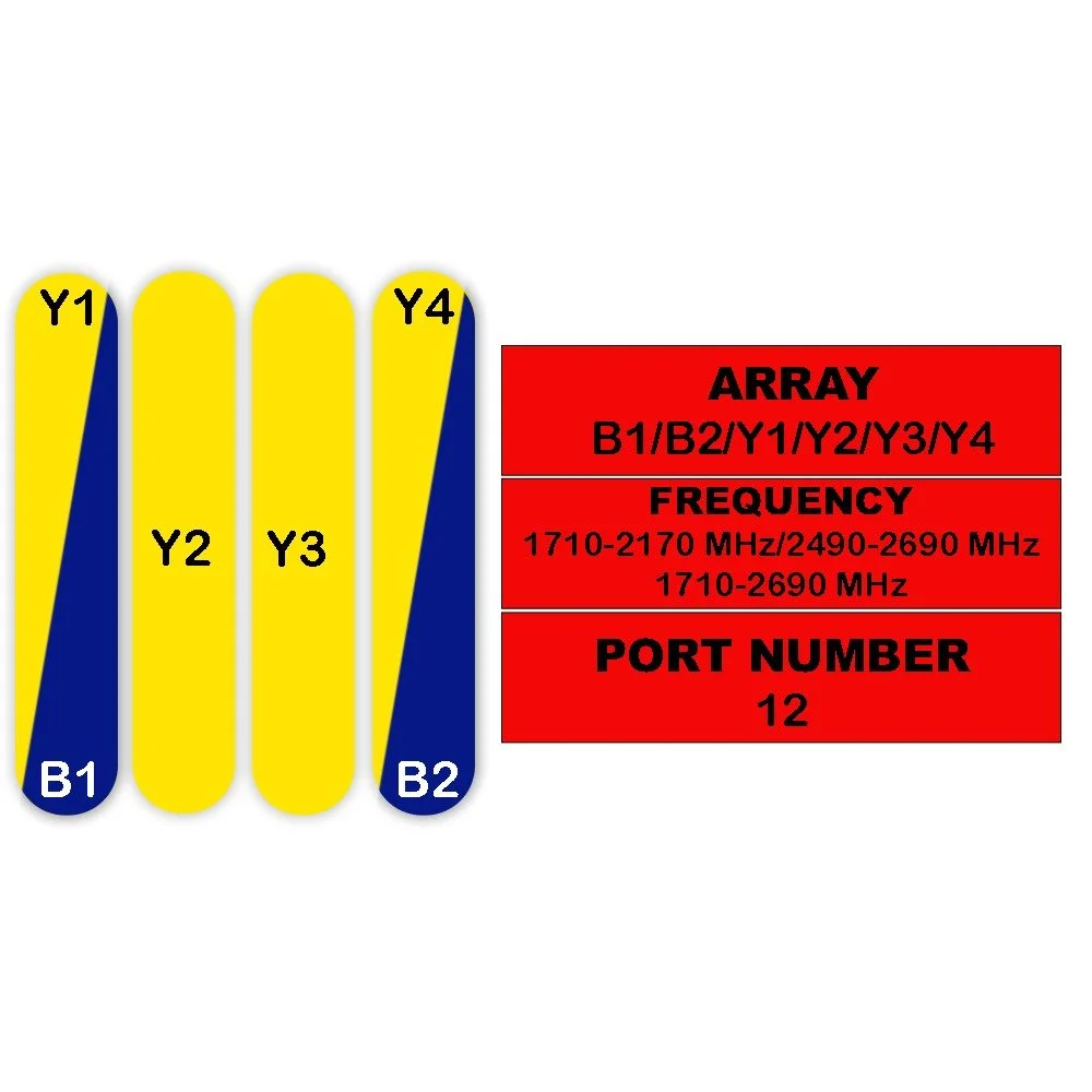
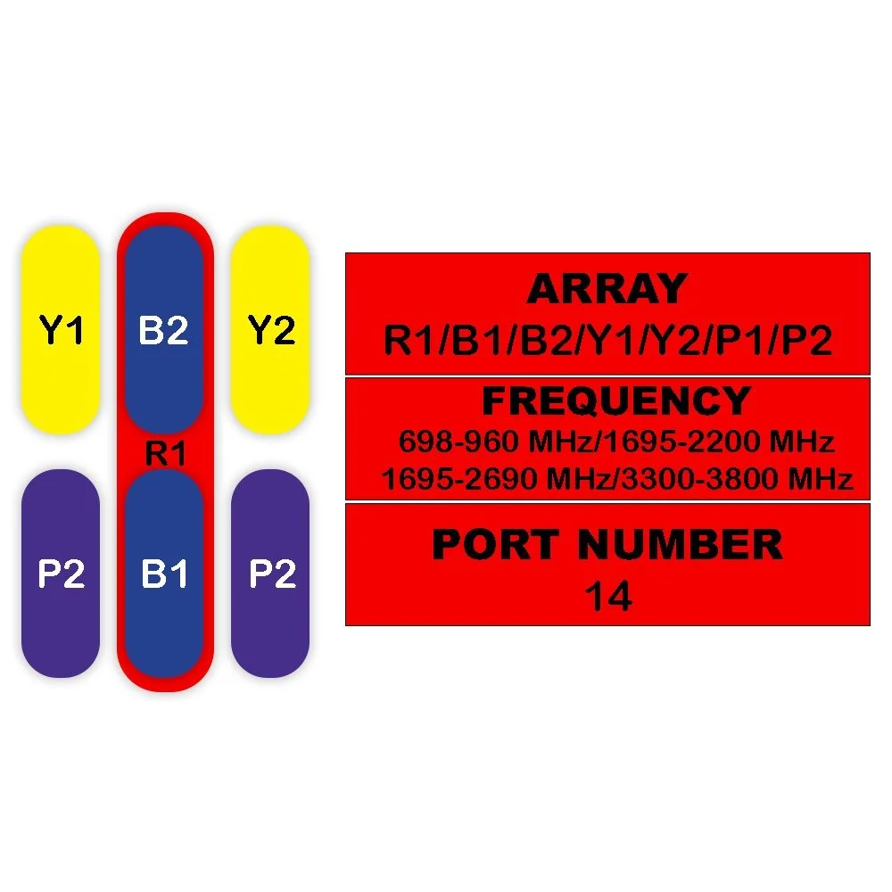
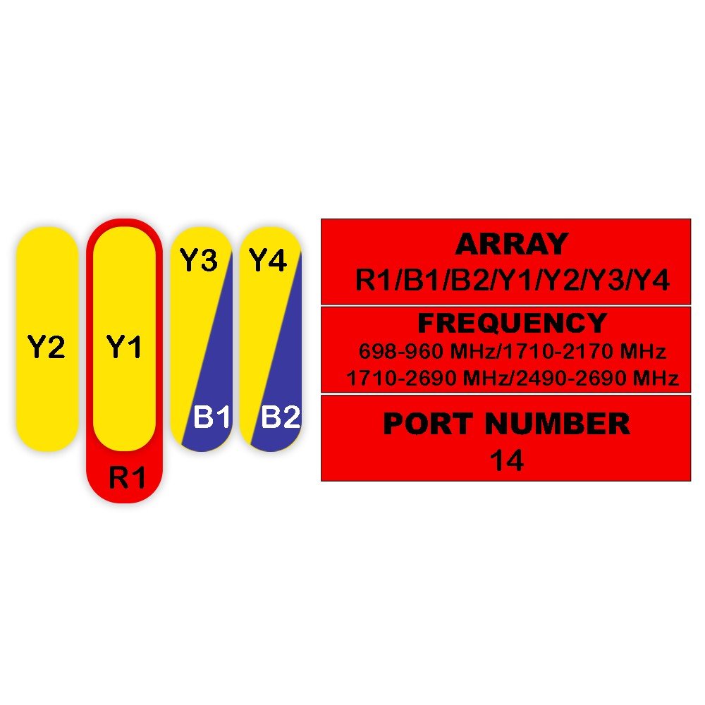
| Parameter | Unit | R1 | Y1 / Y2 | ||||||
|---|---|---|---|---|---|---|---|---|---|
| 690–960 MHz | 1695–2690 MHz | ||||||||
| 690–806 | 790–894 | 880–960 | 1695–1880 | 1850–1990 | 1920–2170 | 2300–2400 | 2490–2690 | ||
| Polarization | — | ±45° | ±45° | ||||||
| Gain (at Mid Tilt) | dBi | 13.8 | 14.2 | 14.7 | 14 | 14.2 | 14.5 | 14.7 | 14.5 |
| Gain (Over All Tilts) | dBi | 13.6 ± 0.6 | 14.0 ± 0.6 | 14.5 ± 0.6 | 13.8 ± 0.6 | 14.0 ± 0.5 | 14.3 ± 0.5 | 14.5 ± 0.5 | 14.3 ± 0.6 |
| Horizontal Beamwidth | degree | 72 ± 4.8 | 69 ± 3.9 | 67 ± 4.1 | 68 ± 4.9 | 67 ± 4.7 | 64 ± 5.1 | 62 ± 5.5 | 60 ± 5.2 |
| Vertical Beamwidth | degree | 16.5 ± 1.5 | 15.4 ± 1.1 | 14.3 ± 0.8 | 14.2 ± 1.0 | 13.4 ± 0.8 | 13 ± 0.8 | 11.2 ± 0.9 | 10.3 ± 0.9 |
| Electrical Downtilt, Continuously Adjustable | degree | 2–16 | 2–12 | ||||||
| First Upper Side Lobe Suppression (typical) | dB | > 15 | > 15 | > 15 | > 15 | > 15 | > 15 | > 15 | > 15 |
| Front-To-Back Ratio ±30° | dB | > 22 | > 23 | > 25 | ≥ 23 | ≥ 23 | > 24 | ≥ 25 | ≥ 25 |
| Isolation (Cross-Polar) | dB | > 25 | > 25 | ||||||
| Isolation (Interband, typical) | dB | > 35 | > 28 (Y1, Y2 // Y3, Y4); > 35 (Y1, Y2 // R1) | ||||||
| Impedance | Ohm | 50 | 50 | ||||||
| VSWR | — | < 1.5 | < 1.5 | ||||||
| Return Loss | dB | > 14 | > 14 | ||||||
| PIM3 (2x43 dBm Carrier) | dBc | < -153 | < -153 | ||||||
| Lightning Protection | — | DC Ground | DC Ground | ||||||
| Maximum Average Input Power per Port, at 50° C Ambient Temperature | Watts | 300 | 250 | ||||||
Electrical Specifications – Y3 / Y4
| Parameter | Unit | Y3 / Y4 | ||||
|---|---|---|---|---|---|---|
| 1695–2690 MHz | ||||||
| 1695–1880 | 1850–1990 | 1920–2170 | 2300–2400 | 2490–2690 | ||
| Polarization | — | ±45° | ||||
| Gain (at Mid Tilt) | dBi | 14.0 | 14.2 | 14.5 | 14.8 | 14.7 |
| Gain (Over All Tilts) | dBi | 13.8 ± 0.6 | 14.0 ± 0.5 | 14.3 ± 0.5 | 14.6 ± 0.5 | 14.5 ± 0.6 |
| Horizontal Beamwidth | degree | 67 ± 4.9 | 65 ± 4.7 | 63 ± 5.1 | 59 ± 5.5 | 59 ± 5.2 |
| Vertical Beamwidth | degree | 15.1 ± 1.1 | 14.1 ± 0.8 | 13.2 ± 0.8 | 11.5 ± 0.9 | 10.4 ± 0.9 |
| Electrical Downtilt, Continuously Adjustable | degree | 2–12 | ||||
| First Upper Side Lobe Suppression (typical) | dB | > 15 | > 15 | > 15 | > 15 | > 15 |
| Front-To-Back Ratio ±30° | dB | ≥ 23 | ≥ 23 | > 24 | ≥ 25 | ≥ 25 |
| Isolation (Cross-Polar) | dB | > 25 | ||||
| Isolation (Interband, typical) | dB | > 28 (Y3, Y4 // Y1, Y2); > 35 (Y3, Y4 // R1) | ||||
| Impedance | Ohm | 50 | ||||
| VSWR | — | < 1.5 | ||||
| Return Loss | dB | > 14 | ||||
| PIM3 (2x43 dBm Carrier) | dBc | < -153 | ||||
| Lightning Protection | — | DC Ground | ||||
| Maximum Average Input Power per Port, at 50° C Ambient Temperature | Watts | 250 | ||||
Electrical Specifications – Y3 / Y4
| Parameter | Unit | Y3 / Y4 | ||||
|---|---|---|---|---|---|---|
| Frequency Range: 1695–2690 MHz | ||||||
| 1695–1880 MHz | 1850–1990 MHz | 1920–2170 MHz | 2300–2400 MHz | 2490–2690 MHz | ||
| Frequency Range | MHz | 1695–1880 | 1850–1990 | 1920–2170 | 2300–2400 | 2490–2690 |
| Polarization | — | ±45° | ||||
| Gain at Mid Tilt | dBi | 14.0 | 14.2 | 14.5 | 14.8 | 14.7 |
| Gain Over All Tilts | dBi | 13.8 ± 0.6 | 14.0 ± 0.5 | 14.3 ± 0.5 | 14.6 ± 0.5 | 14.5 ± 0.6 |
| Horizontal Beamwidth | degree | 67 ± 4.9 | 65 ± 4.7 | 63 ± 5.1 | 59 ± 5.5 | 59 ± 5.2 |
| Vertical Beamwidth | degree | 15.1 ± 1.1 | 14.1 ± 0.8 | 13.2 ± 0.8 | 11.5 ± 0.9 | 10.4 ± 0.9 |
| Electrical Downtilt, Continuously Adjustable | degree | 2–12 | ||||
| First Upper Side Lobe Suppression (typical) | dB | > 15 | > 15 | > 15 | > 15 | > 15 |
| Front-To-Back Ratio ±30° | dB | ≥ 23 | ≥ 23 | > 24 | ≥ 25 | ≥ 25 |
| Isolation Cross-Polar | dB | > 25 | ||||
| Isolation Interband (typical) | dB | > 28 (Y3, Y4 // Y1, Y2); > 35 (Y3, Y4 // R1) | ||||
| Impedance | Ohm | 50 | ||||
| Voltage Standing Wave Ratio (VSWR) | — | < 1.5 | ||||
| Return Loss | dB | > 14 | ||||
| Passive Intermodulation PIM3 (2 × 43 dBm Carrier) | dBc | < -153 | ||||
| Lightning Protection | — | DC Ground | ||||
| Maximum Average Input Power per Port, at 50° C Ambient Temperature | Watts | 250 | ||||
Mechanical Specifications
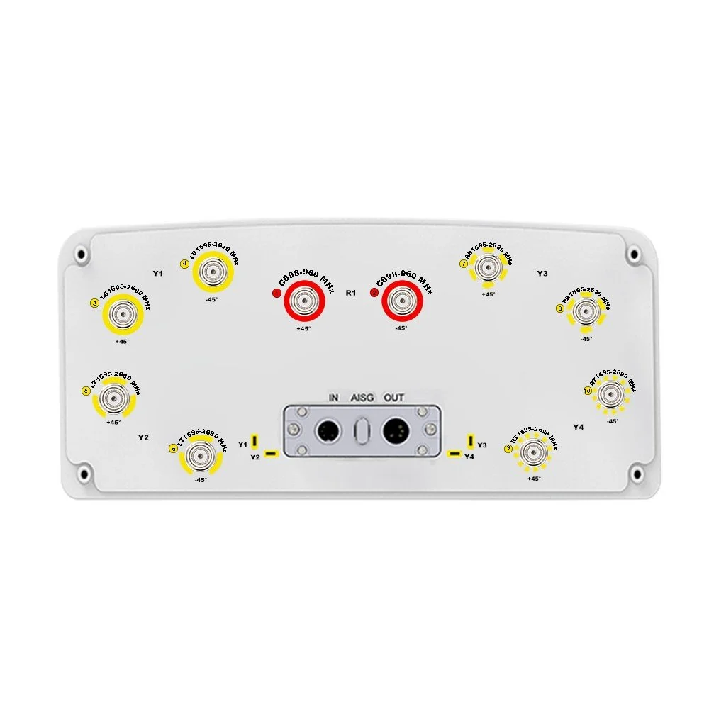
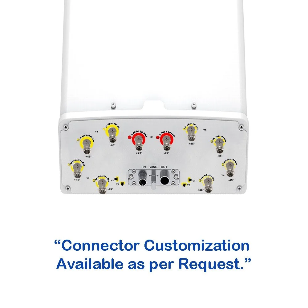
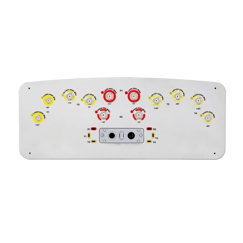
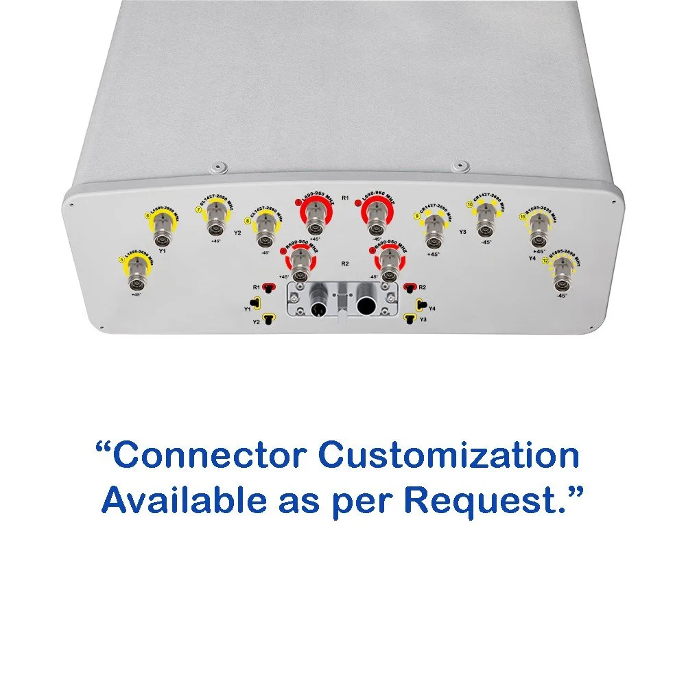
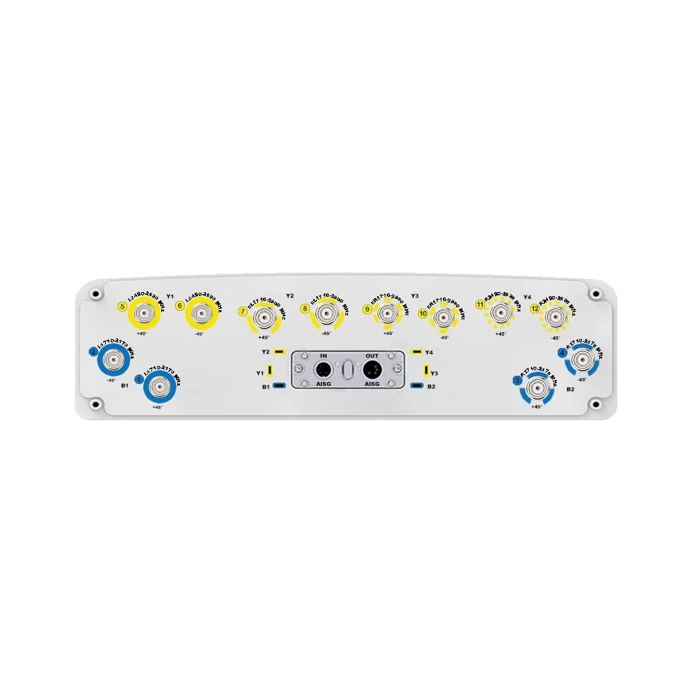
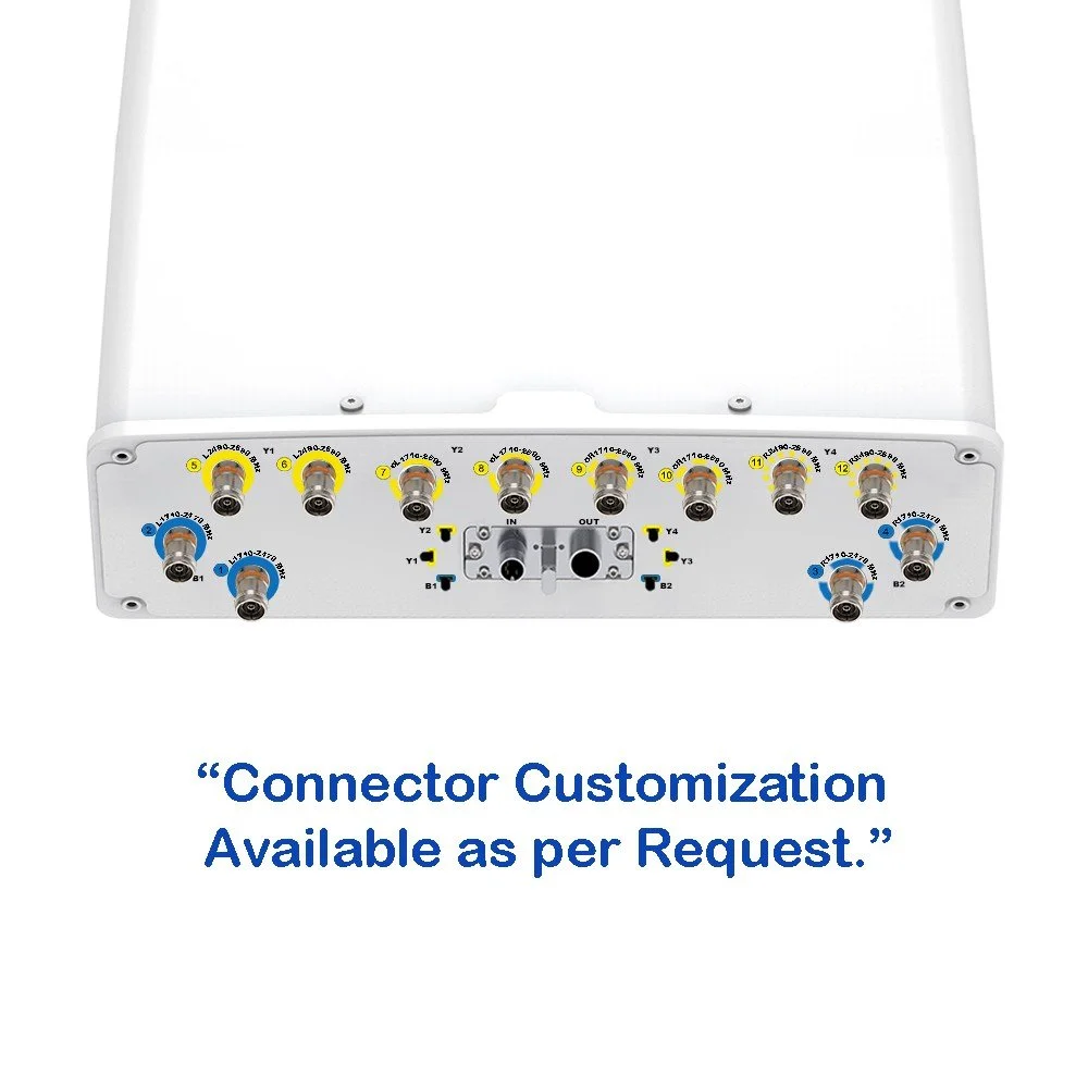
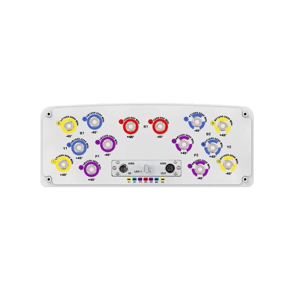
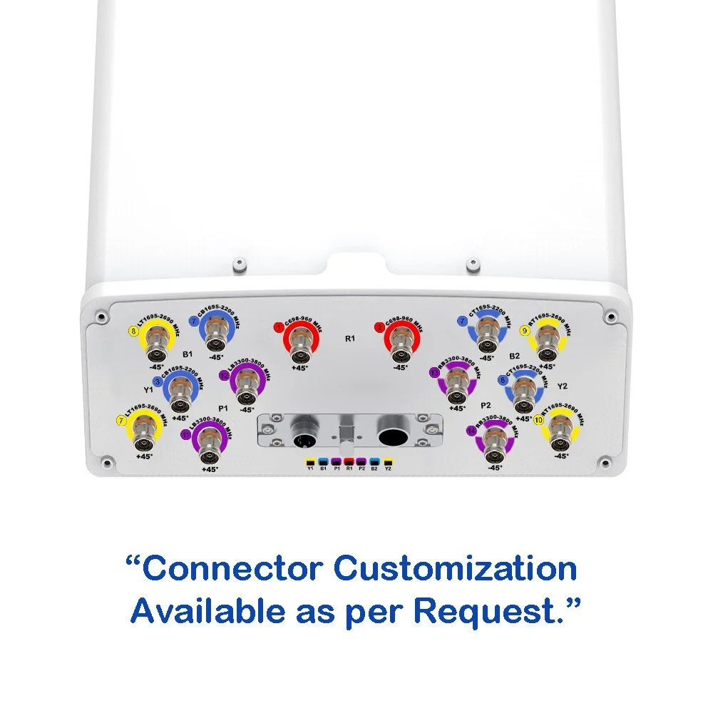
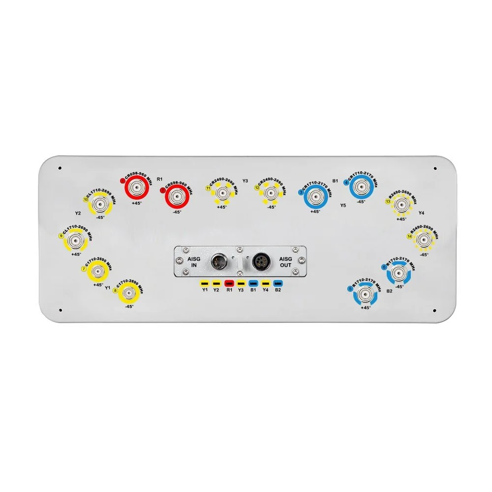
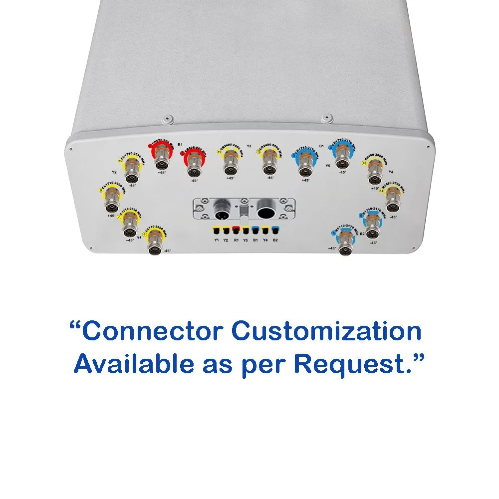
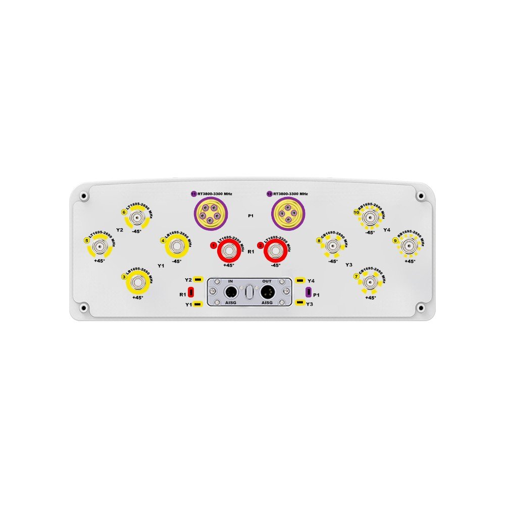
| Connector Type | — | (10 ×) 4.3/10 Female Connectors + (1 ×) MQ5 Male Connector + (1 ×) MQ4 Male Connector |
| Connector Position | — | Bottom |
| Electrical Tilt Control | — | Integrated Remote Electrical Tilt (RET) |
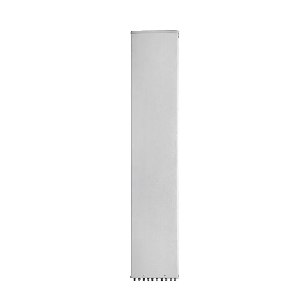
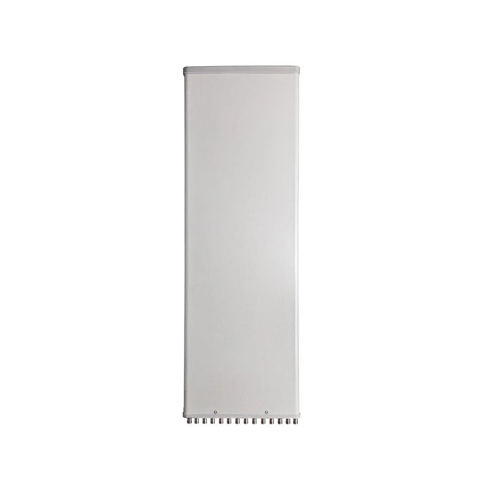
| Radome Material | — | Fiberglass |
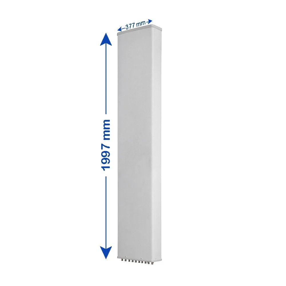
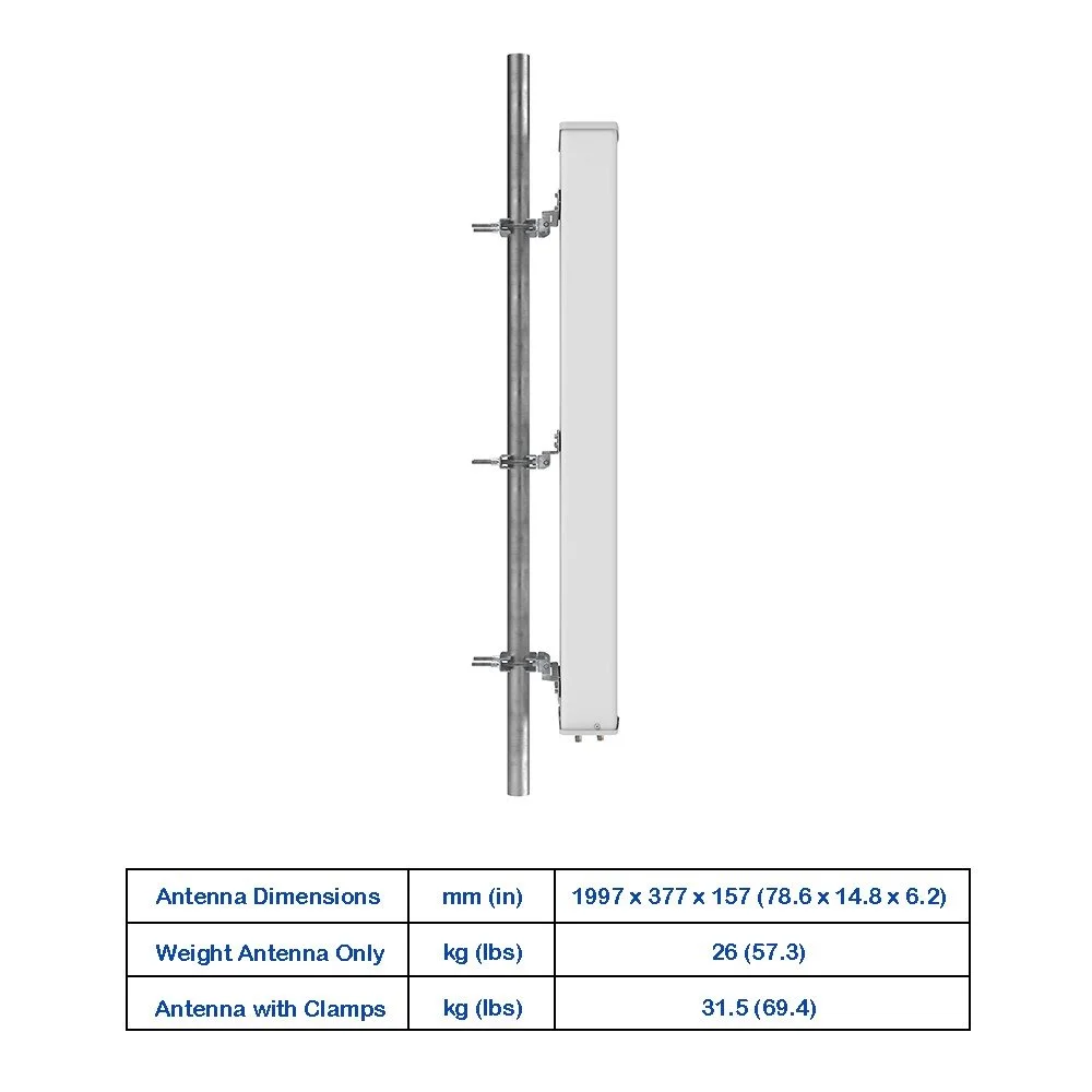
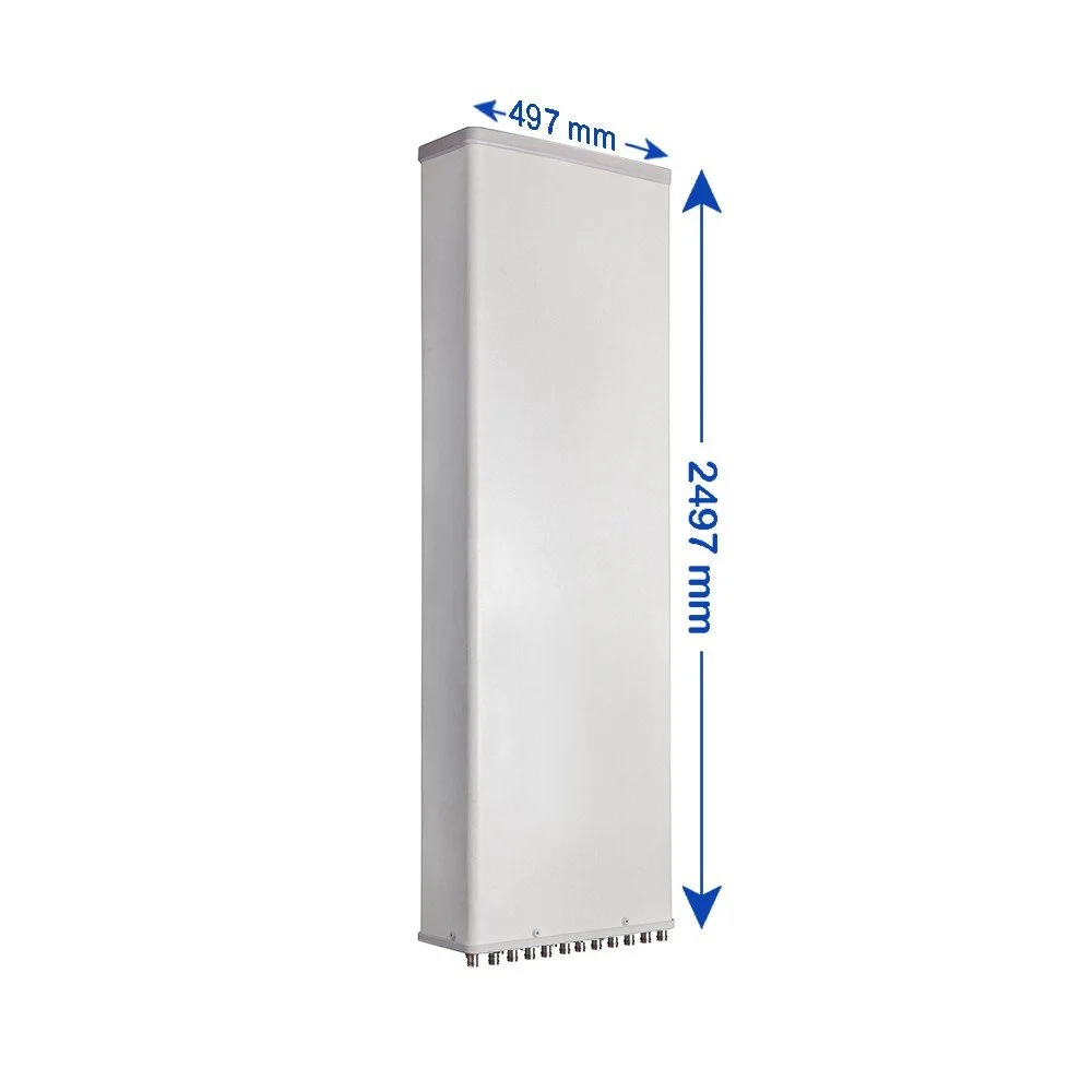
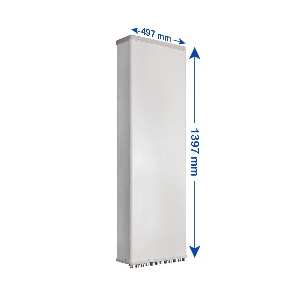
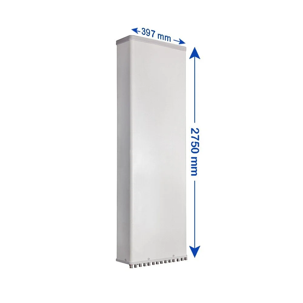
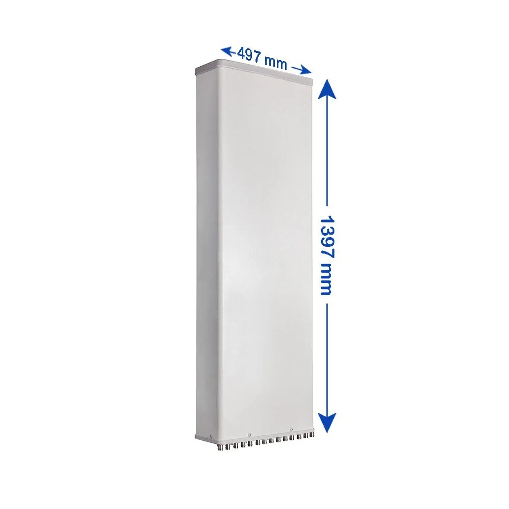
| Antenna Dimensions (Height × Width × Depth) | mm (in) | 1597 × 397 × 157 mm (62.9 × 15.6 × 6.2 inches) |
| Antenna Weight (Antenna Only) | kg (lbs) | 29 kg (63.9 lbs) |
| Antenna Weight (with Clamps) | kg (lbs) | 33 kg (72.8 lbs) |
| Maximum Wind Speed Survival | km/h (mph) | 200 km/h (124.3 mph) |
| Wind Load at 150 km/h – Frontal | N (lbf) | 585 N (131.5 lbf) |
| Wind Load at 150 km/h – Rear | N (lbf) | 655 N (147.2 lbf) |
| Wind Load at 150 km/h – Lateral | N (lbf) | 285 N (64.1 lbf) |
| Operating Temperature Range | °C (°F) | -40 °C to +60 °C (-40 °F to 140 °F) |