 Image 1 of 6
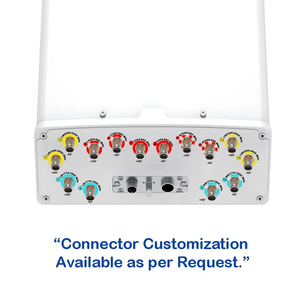 Image 2 of 6
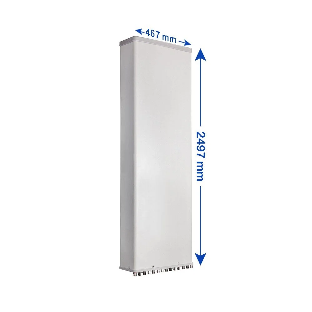 Image 3 of 6
 Image 4 of 6
Image 5 of 6
Image 4 of 6
Image 5 of 6
 Image 6 of 6
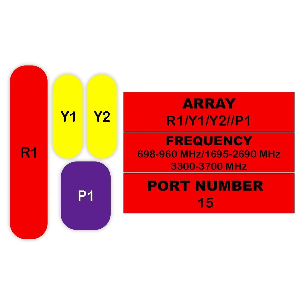
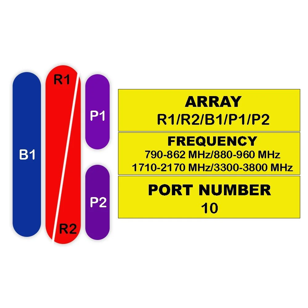
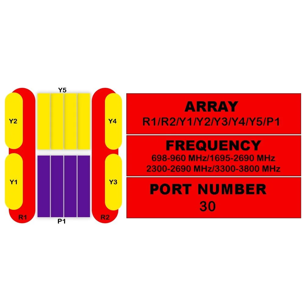
Electrical Specifications
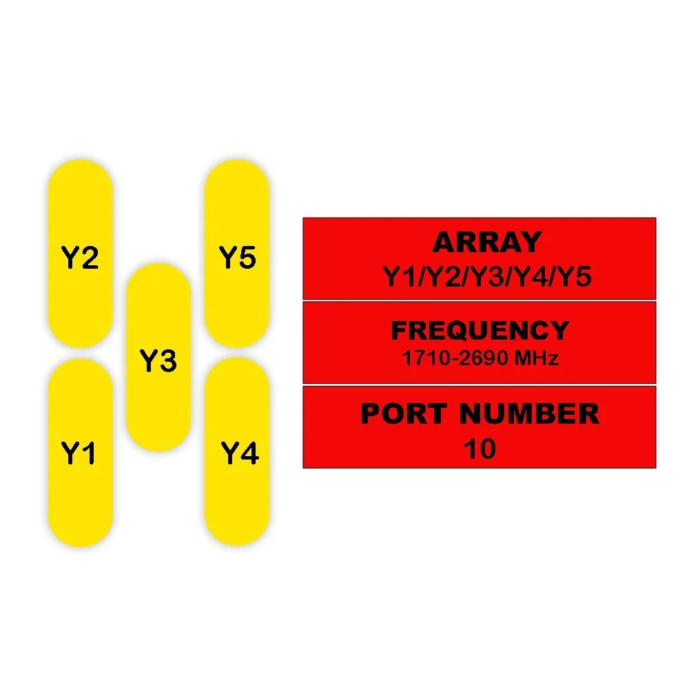
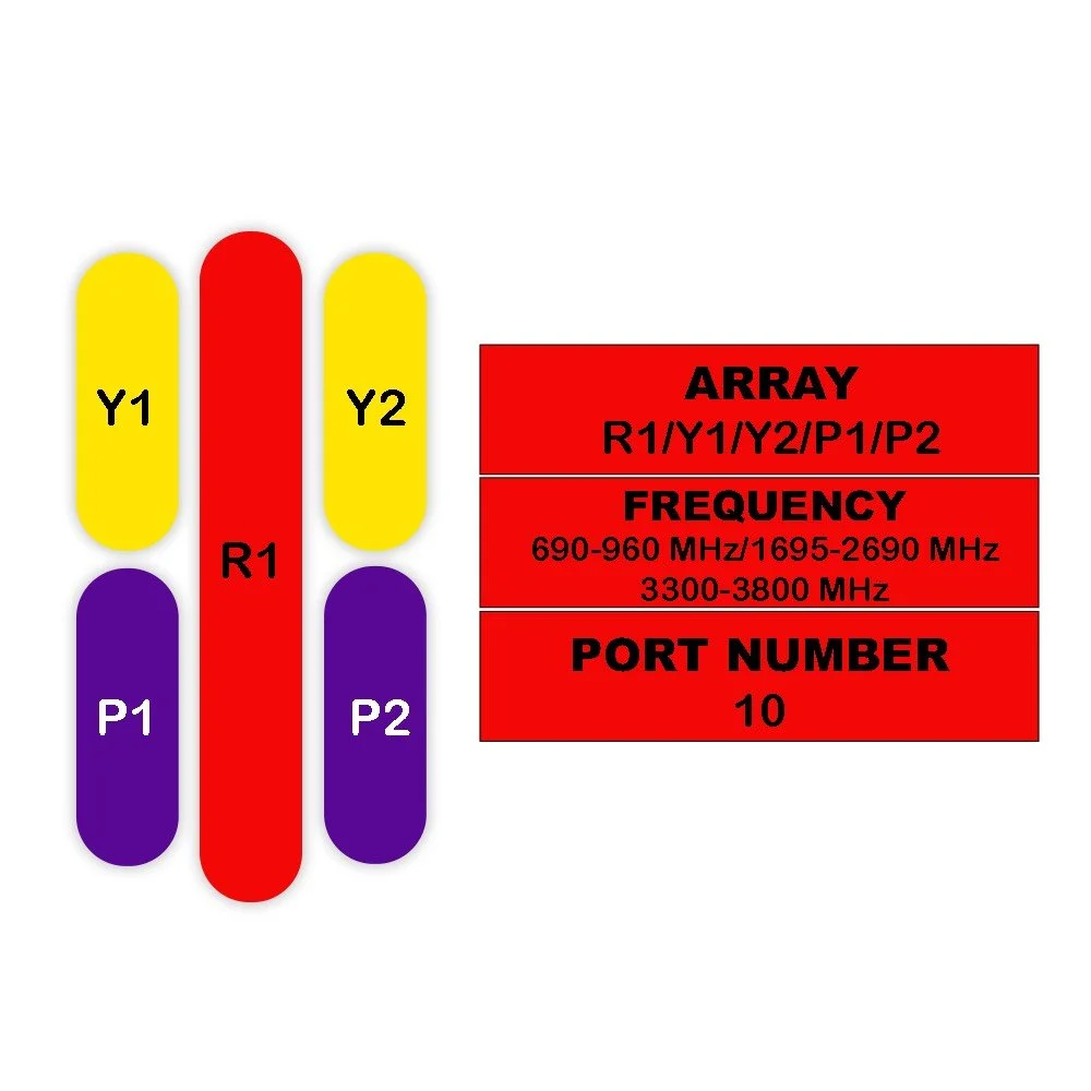
| Parameter | Unit | R1 | R2 | B1 / B2 | Y1 / Y2 |
|---|---|---|---|---|---|
| Frequency Range | MHz | 824–960 | 698–806 1710–1880 2300–2400 |
824–894 880–960 |
1710–1880 2300–2400 |
| Polarization | — | ±45° | ±45° | ±45° | ±45° |
| Gain (Mid Tilt) | dBi | 13.8 | 14.1 | 13.5 | 16.4 / 17.2 |
| Gain (All Tilts) | dBi | 13.6 ± 0.5 | 13.9 ± 0.5 | 13.3 ± 0.6 | 16.2 ± 0.6 / 17.0 ± 0.6 |
| Horizontal Beamwidth | ° | 67 ± 5.5 | 65 ± 6.5 | 64 ± 6.5 | 64 ± 5.5 / 60 ± 4.5 |
| Vertical Beamwidth | ° | 14.8 ± 0.9 | 14.2 ± 0.9 | 16.7 ± 1.1 | 7.4 ± 0.6 / 6.0 ± 0.5 |
| Electrical Downtilt (Adjustable) | ° | 2–14 | 2–14 | 0–10 | 0–10 |
| First Upper Side Lobe Suppression | dB | > 15 | > 15 | > 15 | > 15 |
| Front-To-Back Ratio (±30°) | dB | > 25 | > 25 | > 22 | > 25 |
| Cross Polar Discrimination (Boresight) | dB | > 18 | > 18 | > 18 | > 28 |
| Isolation – Cross Polar | dB | > 25 | > 25 | > 25 | > 25 |
| Isolation – Port-to-Port | dB | > 28 | > 25 (R2//R3) > 28 (R2, R3//R1, B1, B2, Y1, Y2) |
> 28 | > 28 |
| Impedance | Ohm | 50 | 50 | 50 | 50 |
| VSWR | — | < 1.5 | < 1.5 | < 1.5 | < 1.5 |
| Return Loss | dB | > 14 | > 14 | > 14 | > 14 |
| PIM3 (2×43 dBm Carrier) | dBc | < -150 | < -150 | < -150 | < -150 |
| Lightning Protection | — | DC Ground | DC Ground | DC Ground | DC Ground |
| Maximum Avg. Input Power per Port (50°C) | Watts | 500 | 500 | 600 (B1+Y1 / B2+Y2) | 600 (B1+Y1 / B2+Y2) |
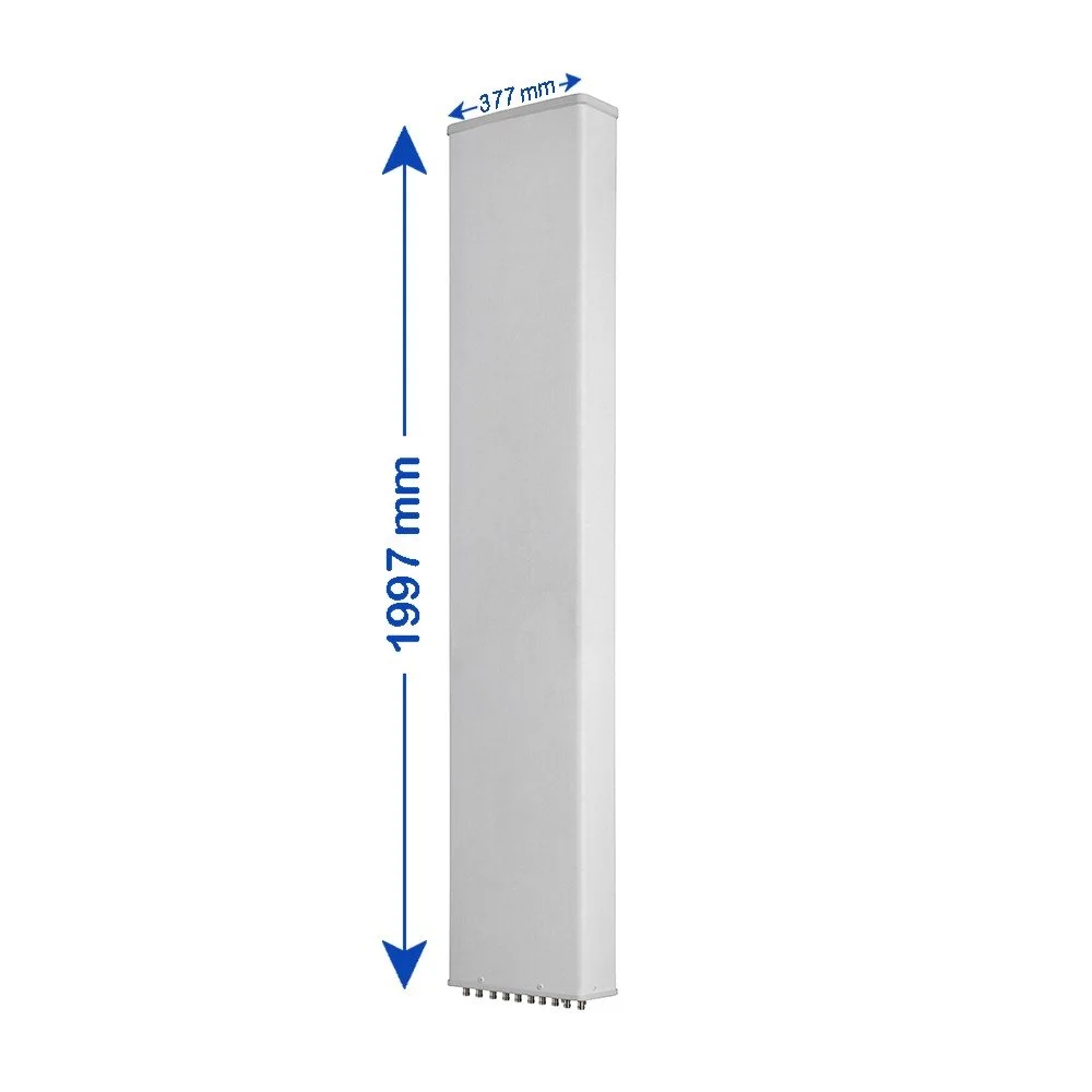
Mechanical Specifications
| Parameter | Description | Unit | Value |
|---|---|---|---|
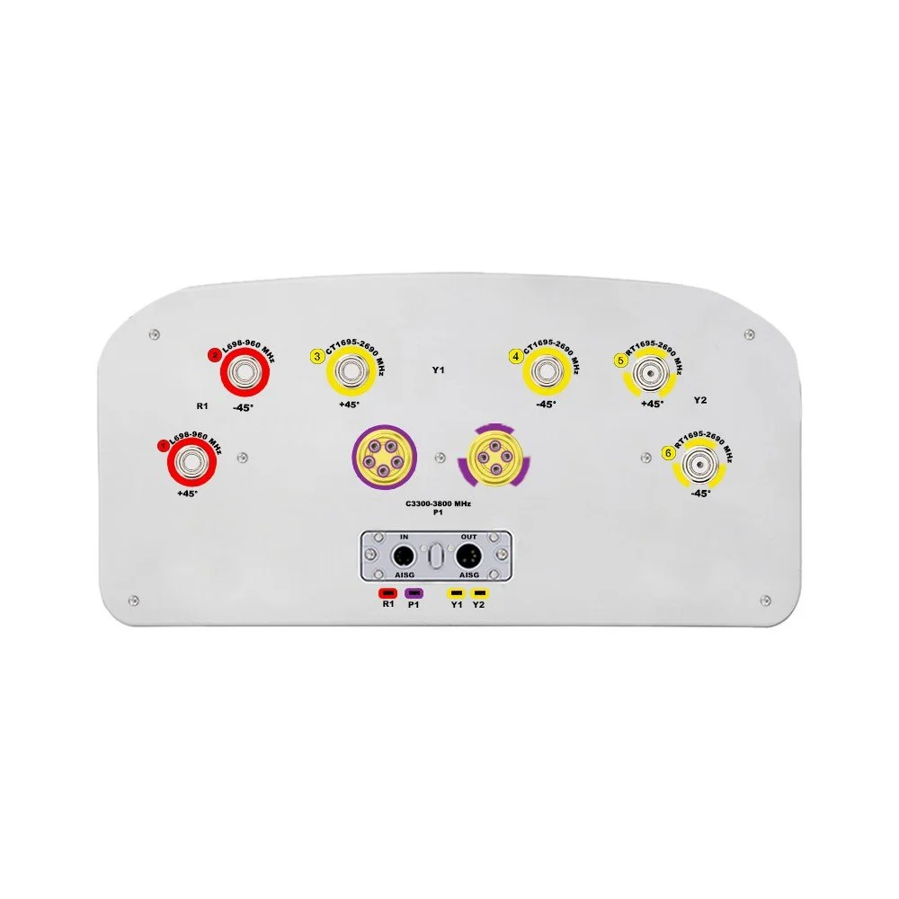
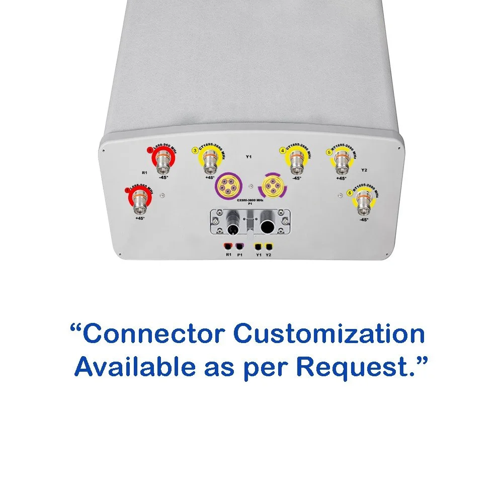
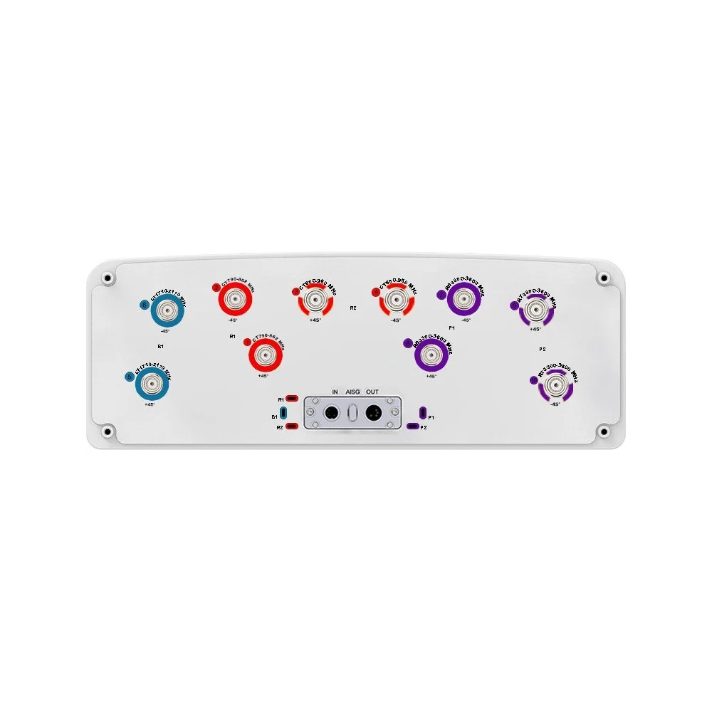
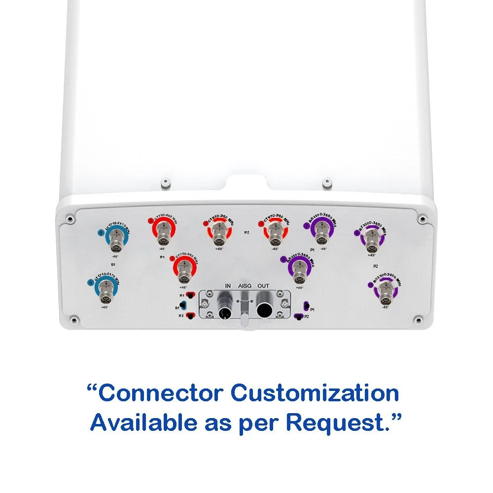
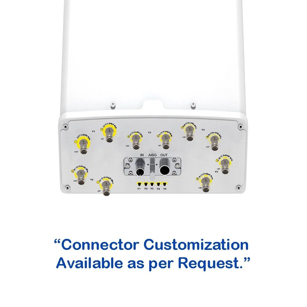
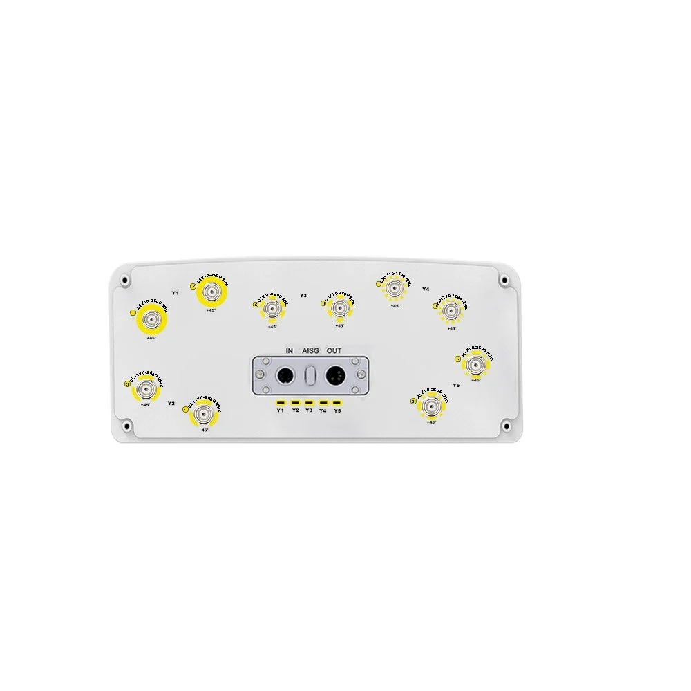
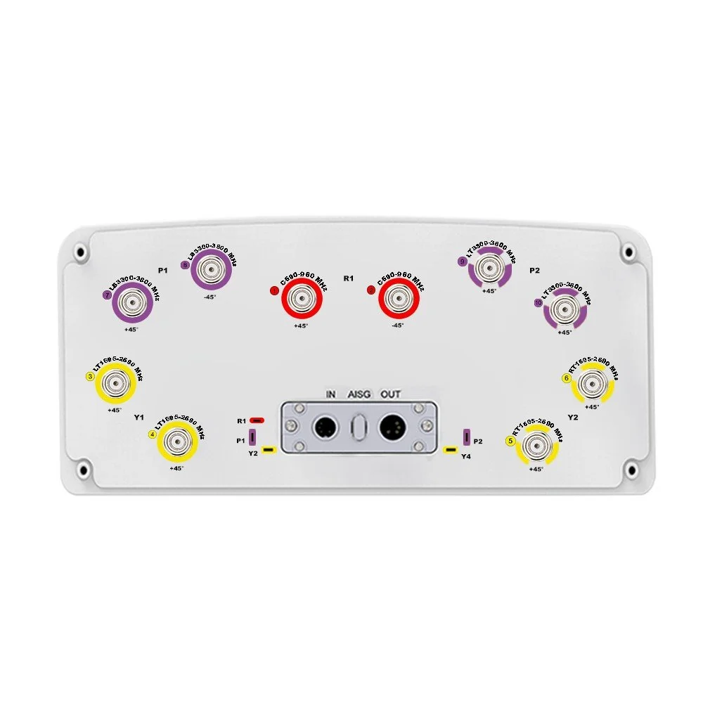
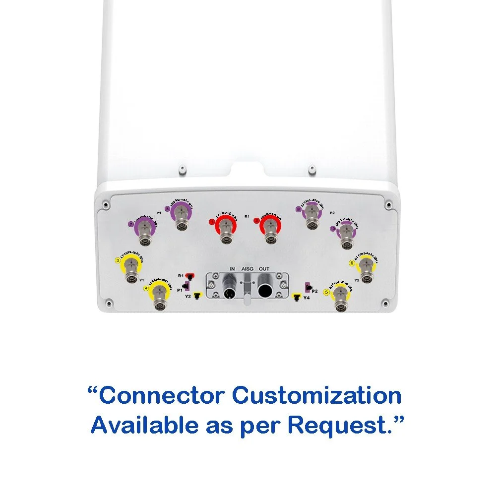
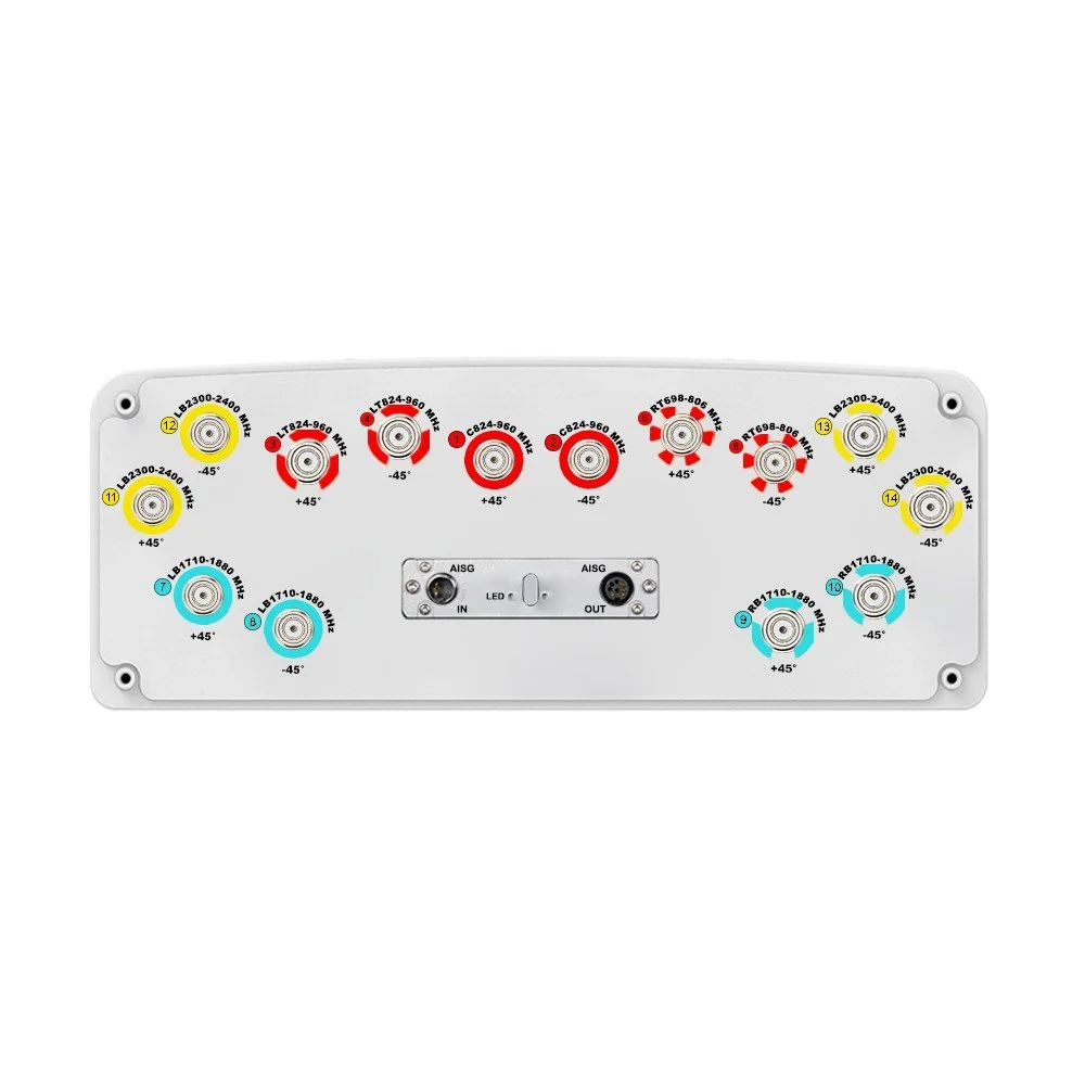
| Connector Type | — | — | (14×) 7/16-DIN Female |
| Connector Position | — | — | Bottom |
| Electrical Tilt Control | — | — | Integrated RET |
| Radome Material | — | — | Fiberglass |
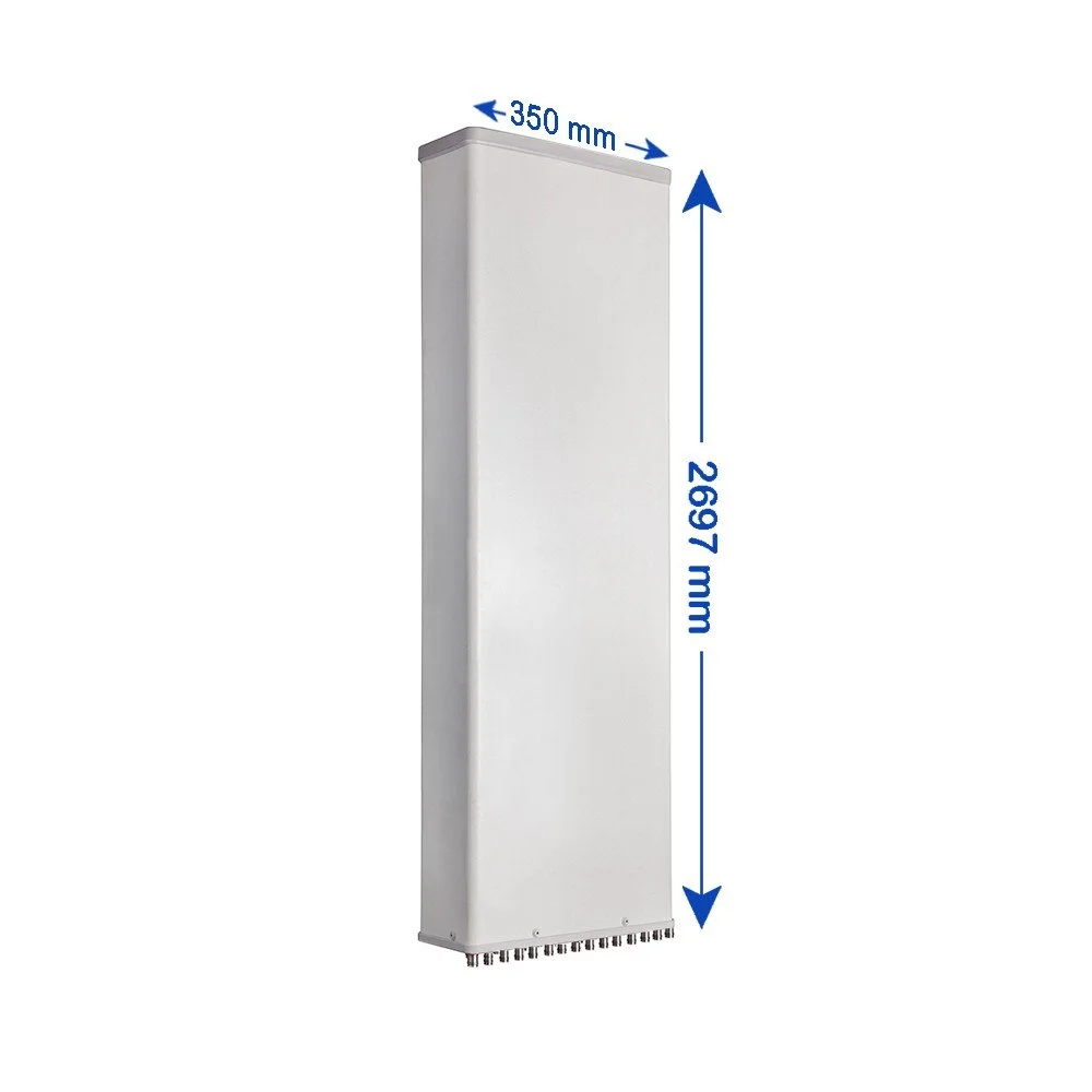
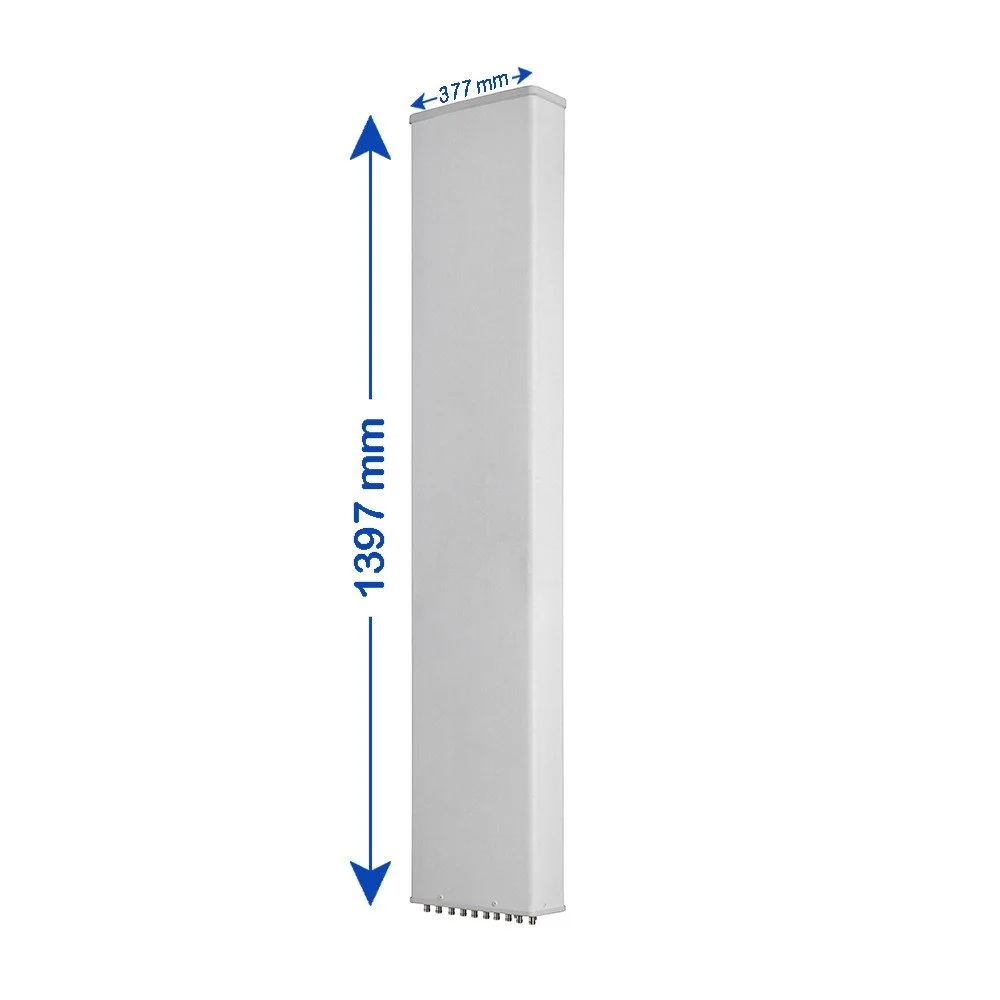
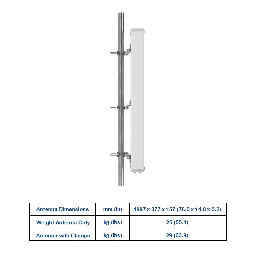
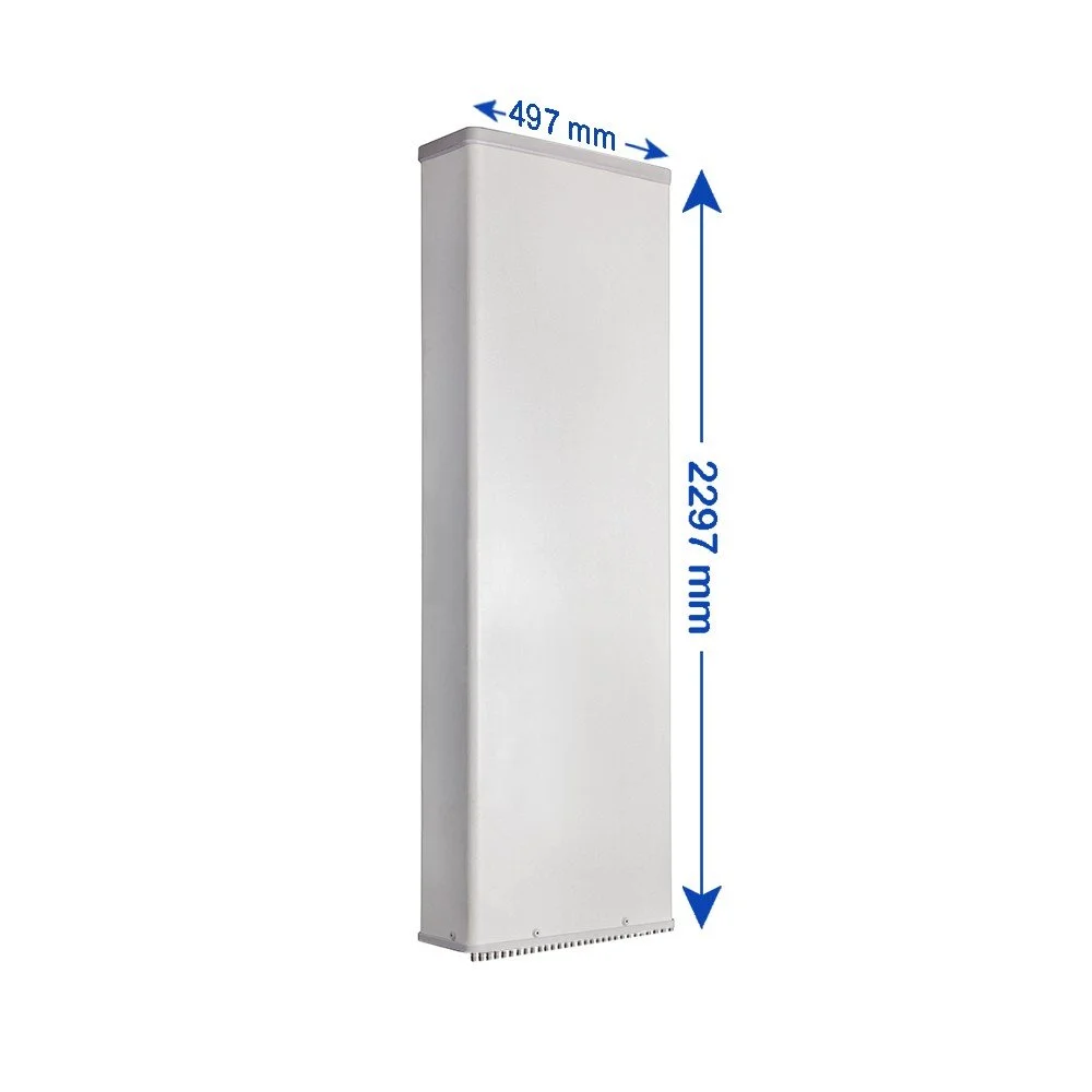
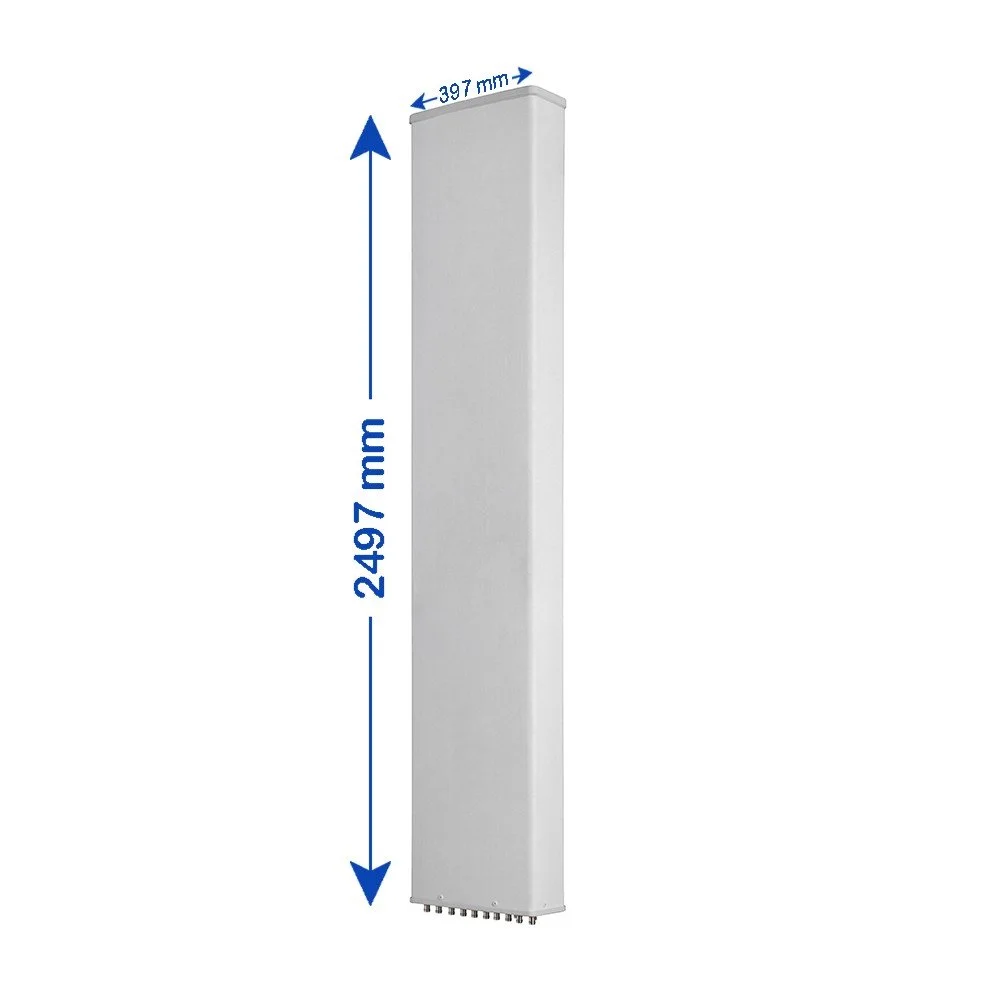
| Antenna Dimensions (H × W × D) | — | mm (in) | 2497 × 467 × 167 (98.3 × 18.4 × 6.6) |
| Antenna Weight | Antenna Only | kg (lbs) | 39 (86.0) |
| Antenna Weight | With Clamps | kg (lbs) | 48 (105.8) |
| Maximum Wind Speed | — | km/h (mph) | 200 (124.3) |
| Wind Load at 150 km/h | Frontal | N (lbf) | 1080 (242.8) |
| Wind Load at 150 km/h | Rear | N (lbf) | 1205 (270.9) |
| Wind Load at 150 km/h | Lateral | N (lbf) | 475 (106.8) |
| Operating Temperature | — | °C (°F) | -40 to +60 (-40 to +140) |