 Image 1 of 6
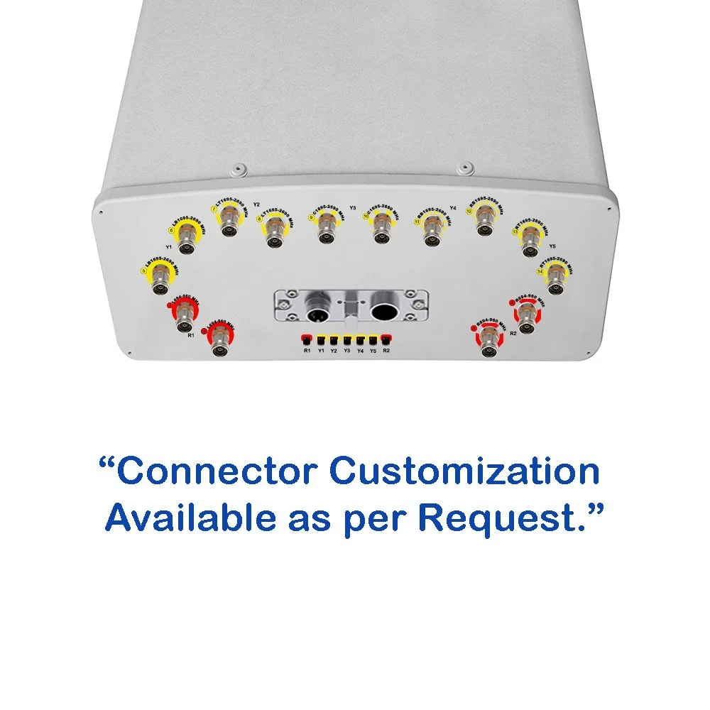 Image 2 of 6
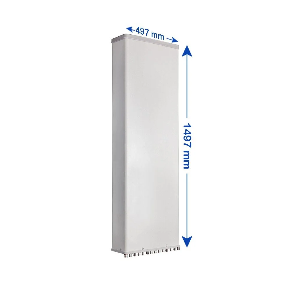 Image 3 of 6
 Image 4 of 6
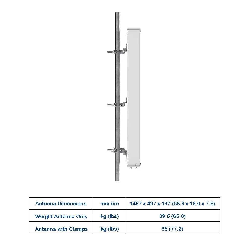 Image 5 of 6
 Image 6 of 6
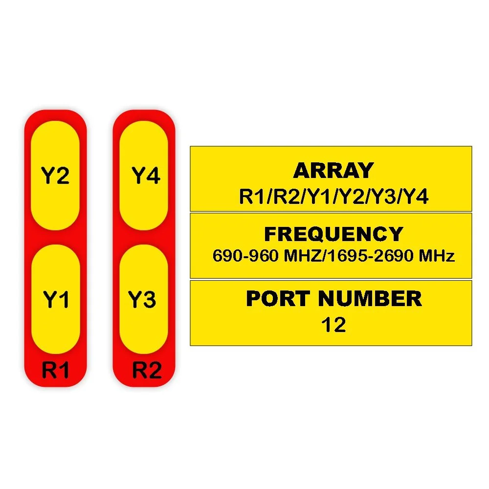
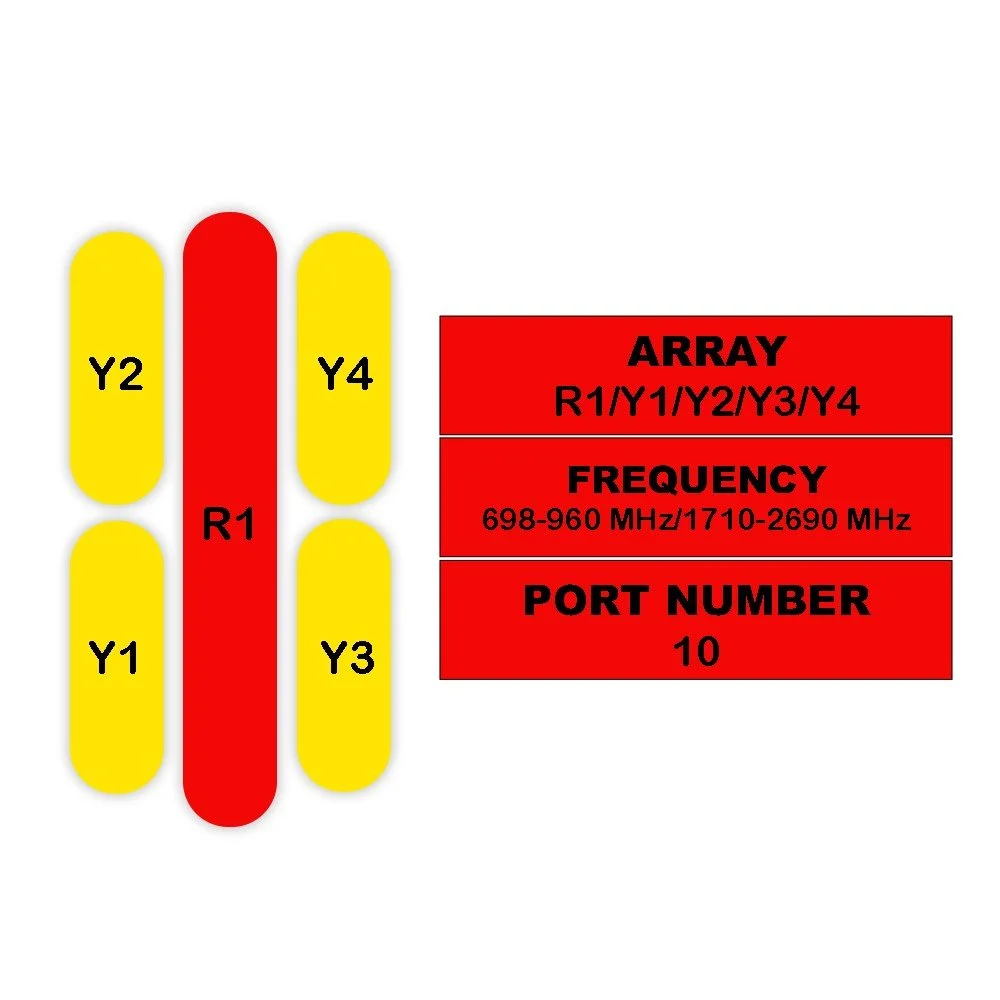
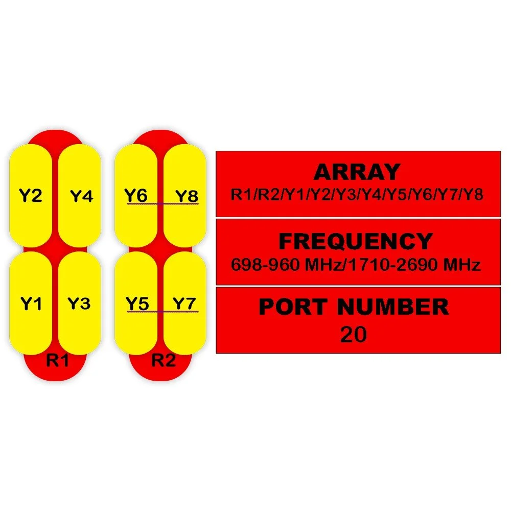
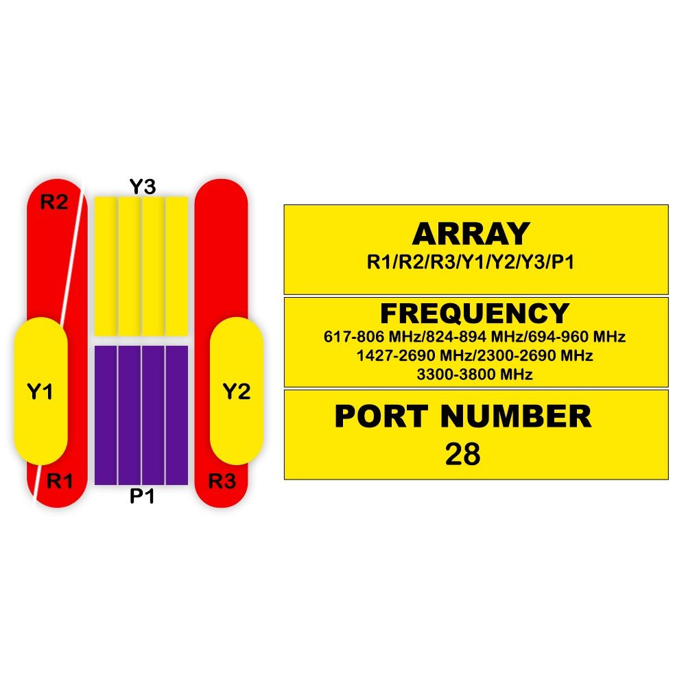
Electrical Specifications – R1 / R2
| Parameter | Unit | 694–824 MHz | 806–896 MHz | 880–960 MHz |
|---|---|---|---|---|
| Frequency Range | MHz | 694–960 | ||
| Polarization | — | ±45° | ||
| Gain – Mid Tilt | dBi | 14.0 | 14.3 | 14.6 |
| Gain – Over All Tilts | dBi | 13.8 ± 0.5 | 14.1 ± 0.5 | 14.4 ± 0.4 |
| Horizontal Beamwidth | degree | 67 ± 4.5 | 65 ± 4.5 | 62 ± 4.5 |
| Vertical Beamwidth | degree | 14.9 ± 1.1 | 13.6 ± 0.9 | 12.4 ± 0.8 |
| Electrical Downtilt (Continuous) | degree | 2–12 | ||
| Tilt Accuracy | degree | < 1 | < 1 | < 1 |
| Upper Side Lobe – First | dB | > 15 | > 15 | > 15 |
| Upper Side Lobe – Peak to 20° | dB | > 15 | > 15 | > 15 |
| Front-to-Back Ratio (±30°) | dB | > 22 | > 23 | > 24 |
| Cross Polar Discrimination – Boresight | dB | > 18 | > 18 | > 18 |
| Cross Polar Discrimination – Sector | dB | > 8.0 | > 7.0 | > 5.5 |
| Isolation – Cross Polar | dB | > 25 | ||
| Isolation – Port to Port | dB |
> 28 (R1,R2 // Y1,Y2,Y3,Y4,Y5) > 25 (R1 // R2) |
||
| Impedance | Ohm | 50 | ||
| VSWR | — | < 1.5 | ||
| Return Loss | dB | > 14 | ||
| PIM3 (2 × 43 dBm) | dBc | < -150 | ||
| Lightning Protection | — | DC Ground | ||
| Max Avg Input Power per Port (50°C) | Watts | 250 | ||
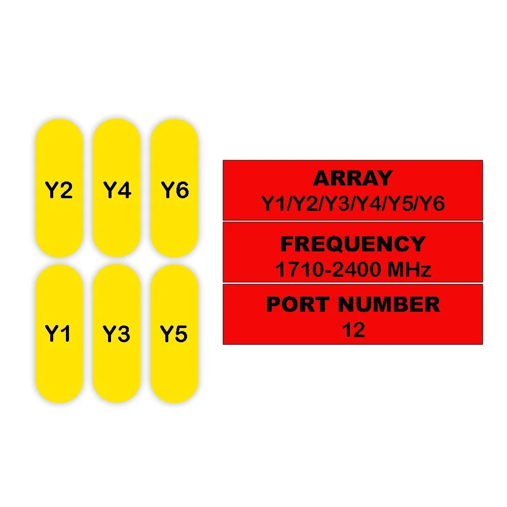
Electrical Specifications – Y1 / Y3 / Y4 & Y2 / Y5
| Parameter | Unit | Y1 / Y3 / Y4 (1695–2690 MHz) | Y2 / Y5 (1695–2690 MHz) | ||||||||
|---|---|---|---|---|---|---|---|---|---|---|---|
| 1695–1880 | 1850–1990 | 1920–2170 | 2300–2400 | 2490–2690 | 1695–1880 | 1850–1990 | 1920–2170 | 2300–2400 | 2490–2690 | ||
| Frequency Range | MHz | 1695–2690 | 1695–2690 | ||||||||
| Polarization | — | ±45° | ±45° | ||||||||
| Gain – Mid Tilt | dBi | 14.0 | 14.3 | 14.6 | 14.9 | 15.1 | 13.8 | 14.1 | 14.4 | 14.7 | 14.9 |
| Gain – Over All Tilts | dBi | 13.8 ± 0.7 | 14.1 ± 0.5 | 14.4 ± 0.6 | 14.7 ± 0.5 | 14.9 ± 0.6 | 13.6 ± 0.7 | 13.9 ± 0.5 | 14.2 ± 0.6 | 14.5 ± 0.5 | 14.7 ± 0.6 |
| Horizontal Beamwidth | degree | 69 ± 6.0 | 67 ± 6.0 | 65 ± 6.0 | 63 ± 5.0 | 63 ± 6.0 | 69 ± 6.0 | 67 ± 6.0 | 65 ± 6.0 | 63 ± 5.0 | 63 ± 6.0 |
| Vertical Beamwidth | degree | 12.5 ± 0.6 | 11.5 ± 0.6 | 10.7 ± 0.6 | 9.4 ± 0.5 | 8.5 ± 0.4 | 12.5 ± 0.6 | 11.5 ± 0.6 | 10.7 ± 0.6 | 9.4 ± 0.5 | 8.5 ± 0.4 |
| Electrical Downtilt (Continuous) | degree | 2–12 | 2–12 | ||||||||
| Tilt Accuracy | degree | < 1 | < 1 | < 1 | < 1 | < 1 | < 1 | < 1 | < 1 | < 1 | < 1 |
| Upper Side Lobe – First | dB | > 15 | > 15 | > 15 | > 15 | > 15 | > 15 | > 15 | > 15 | > 15 | > 15 |
| Upper Side Lobe – Peak to 20° | dB | > 14 | > 14 | > 14 | > 14 | > 14 | > 14 | > 14 | > 14 | > 14 | > 14 |
| Front-to-Back Ratio (±30°) | dB | > 24 | > 24 | > 25 | > 26 | > 26 | > 24 | > 24 | > 25 | > 26 | > 26 |
| Cross Polar Discrimination – Boresight | dB | > 16 | > 16 | > 16 | > 16 | > 16 | > 16 | > 16 | > 16 | > 16 | > 16 |
| Cross Polar Discrimination – Sector | dB | > 6.0 | > 7.0 | > 7.0 | > 5.0 | > 2.0 | > 6.0 | > 7.0 | > 7.0 | > 6.0 | > 4.0 |
| Isolation – Cross Polar | dB | > 25 | > 25 | ||||||||
| Isolation – Port to Port | dB | > 28 | > 28 | ||||||||
| Impedance | Ohm | 50 | 50 | ||||||||
| VSWR | — | < 1.5 | < 1.5 | ||||||||
| Return Loss | dB | > 14 | > 14 | ||||||||
| PIM3 (2 × 43 dBm) | dBc | < -150 | < -150 | ||||||||
| Lightning Protection | — | DC Ground | DC Ground | ||||||||
| Max Avg Input Power per Port (50°C) | Watts | 200 | 200 | ||||||||
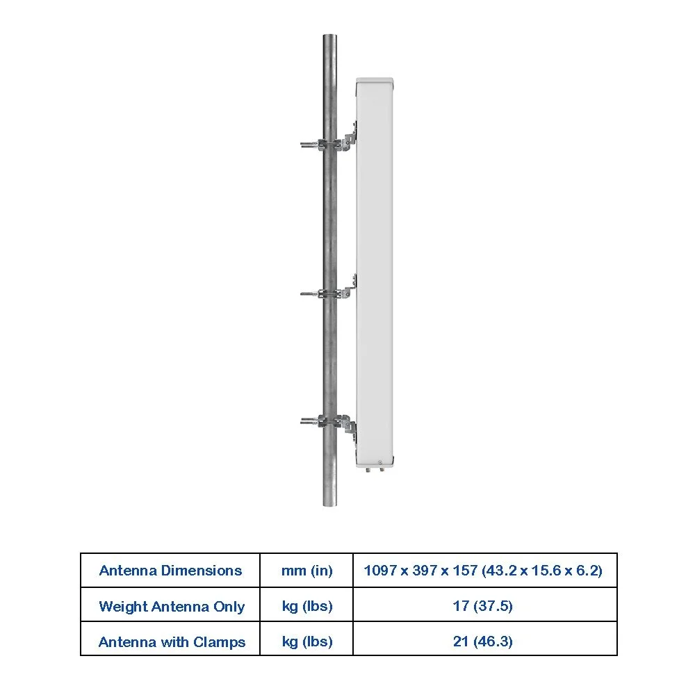
Mechanical Specifications
| Parameter | Details | Unit |
|---|---|---|
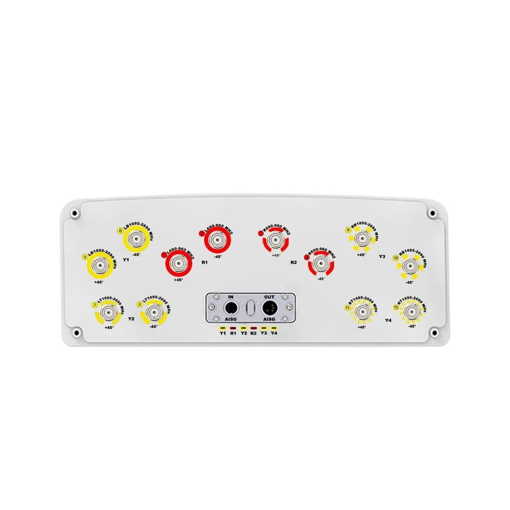
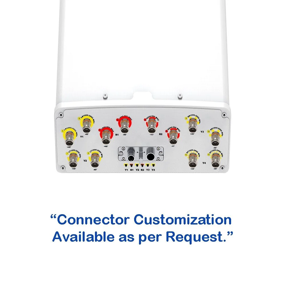
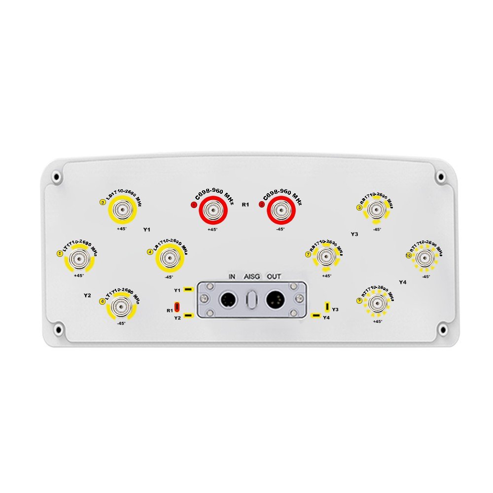
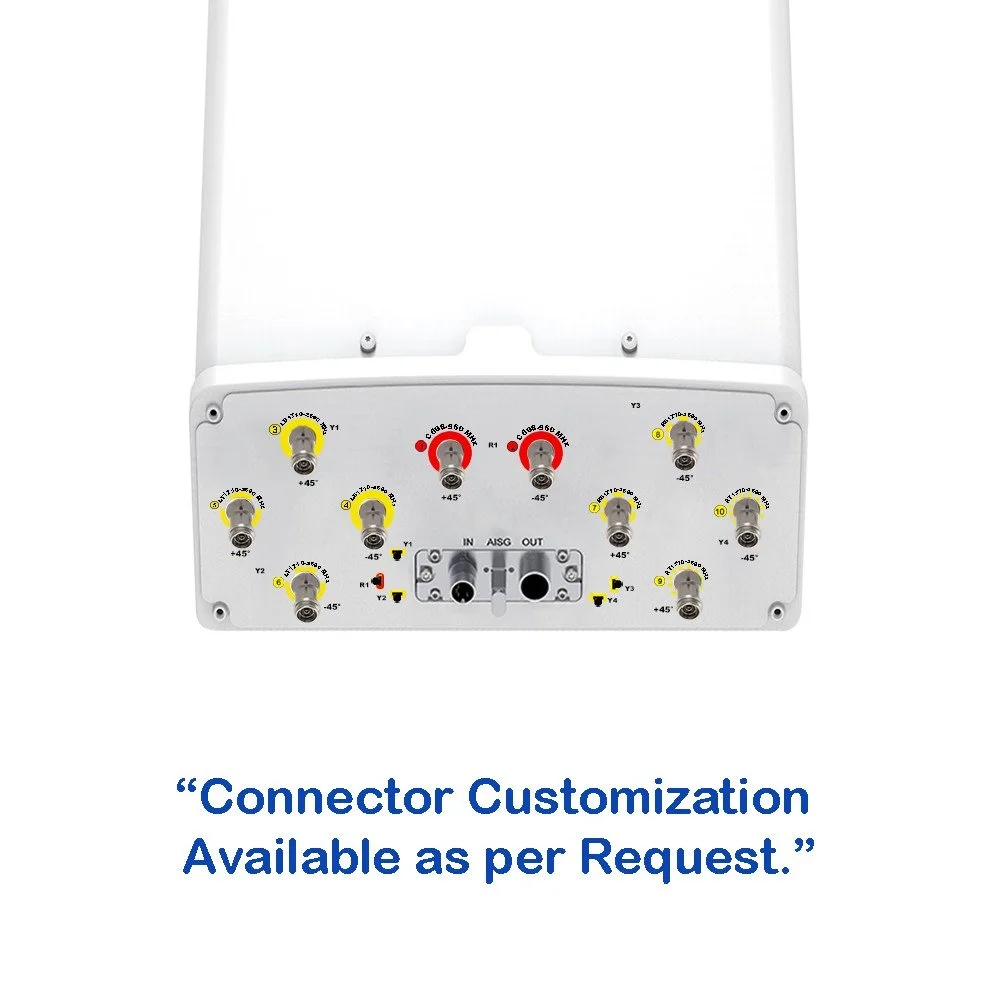
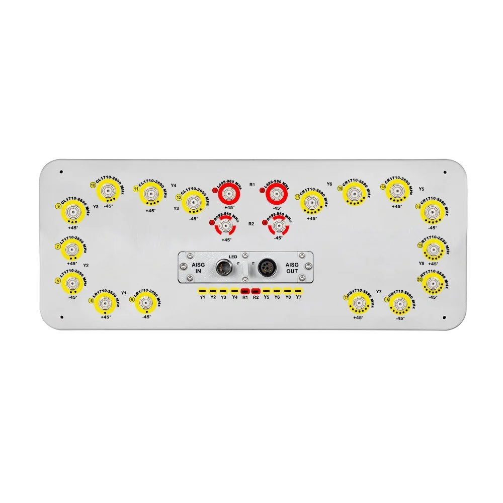
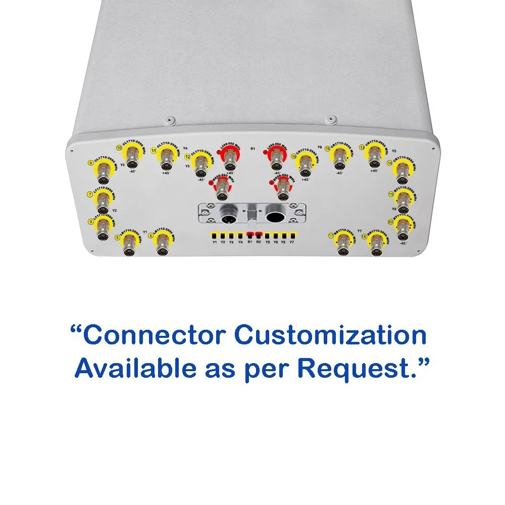
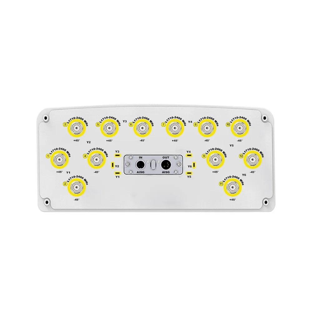
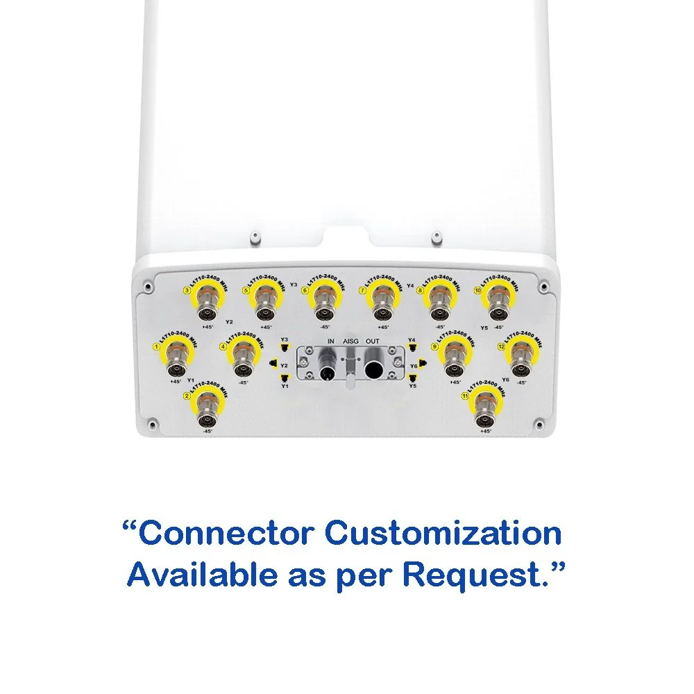
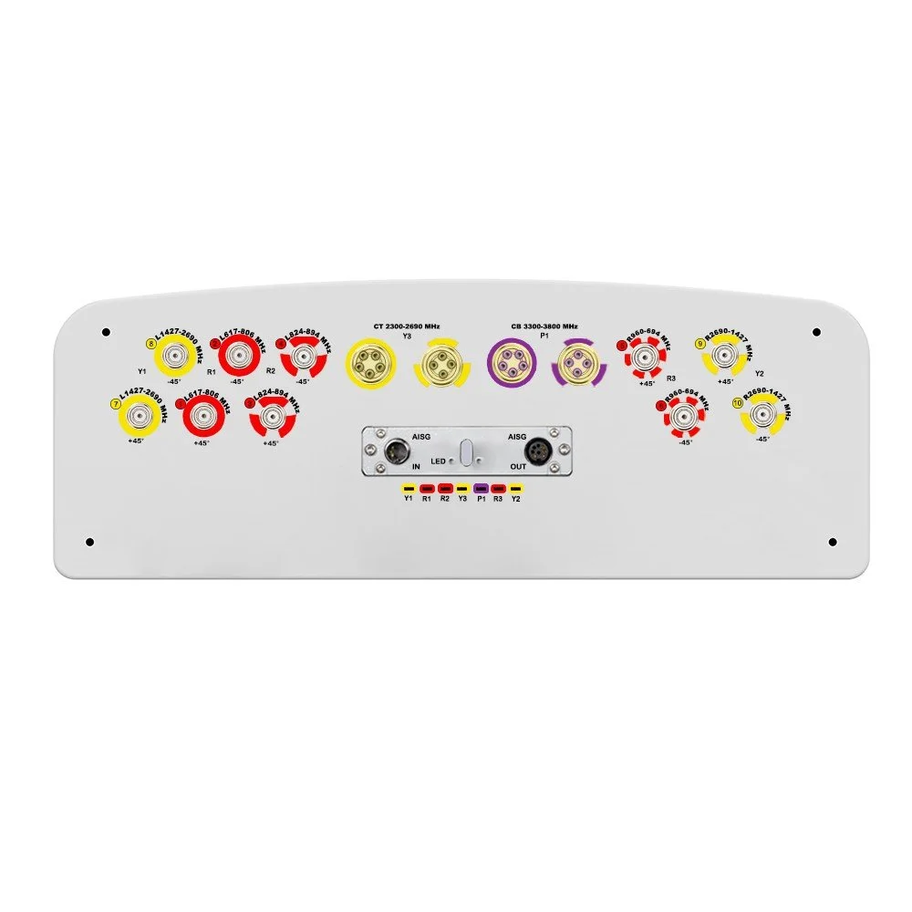
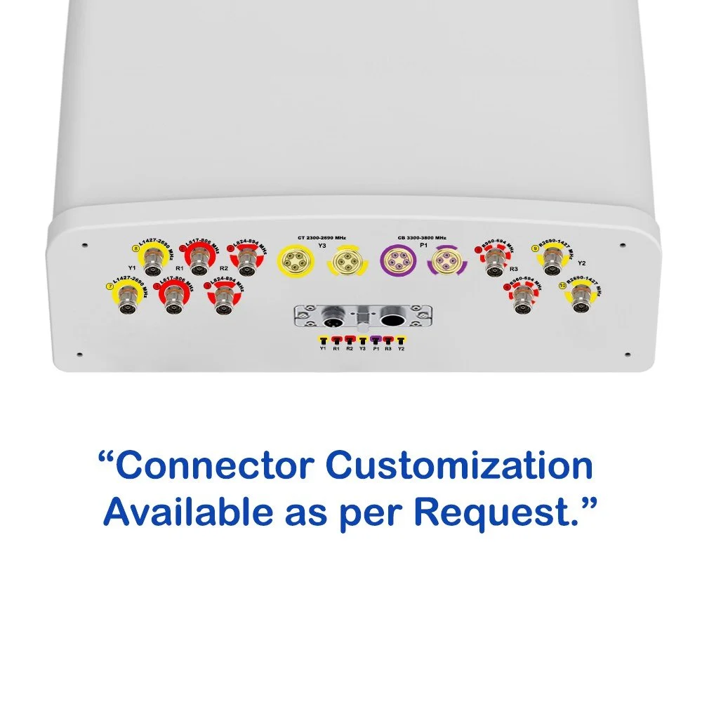
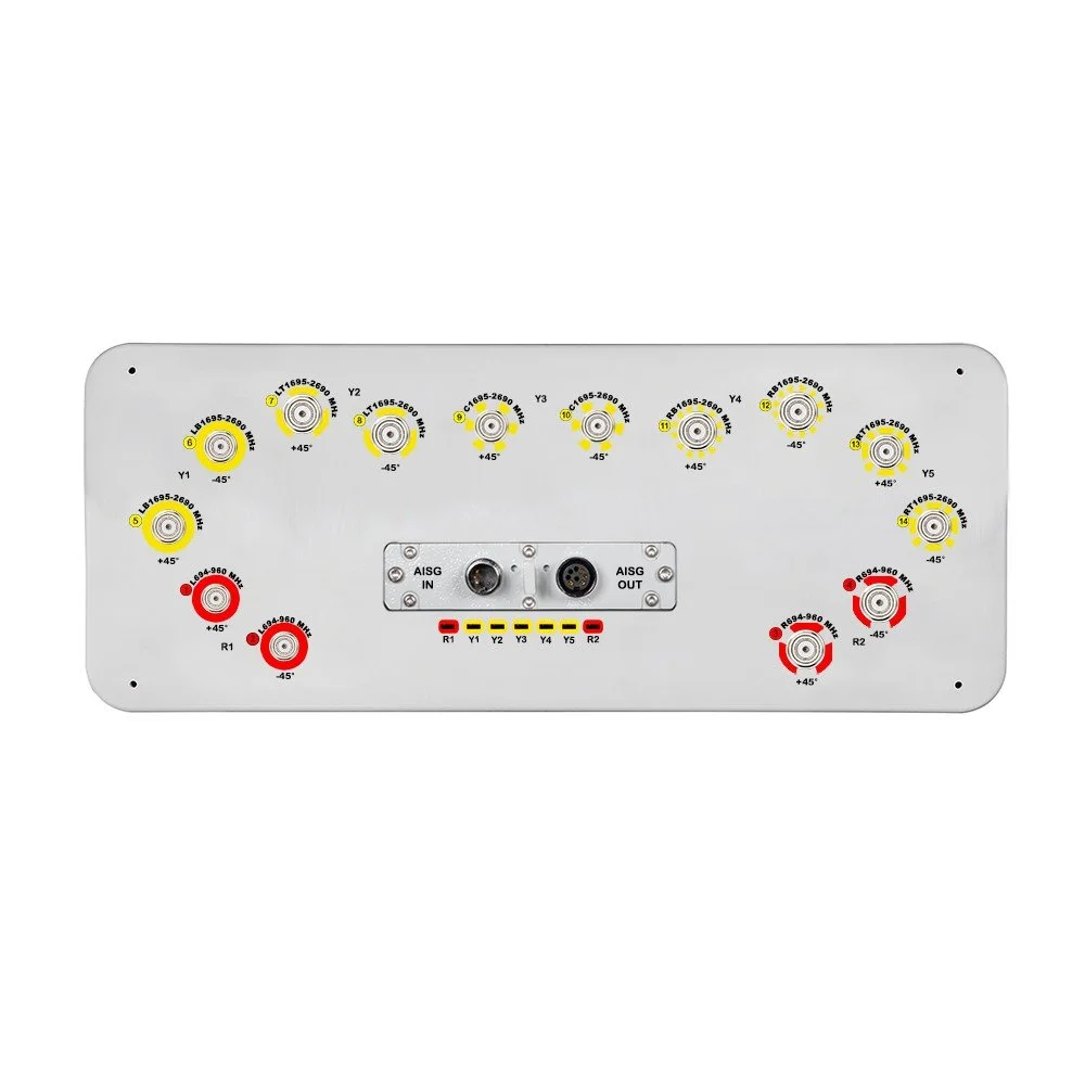
| Connector Type | (14x) 4.3/10 Female | — |
| Connector Position | Bottom | — |
| Electrical Tilt Control | Integrated RET | — |
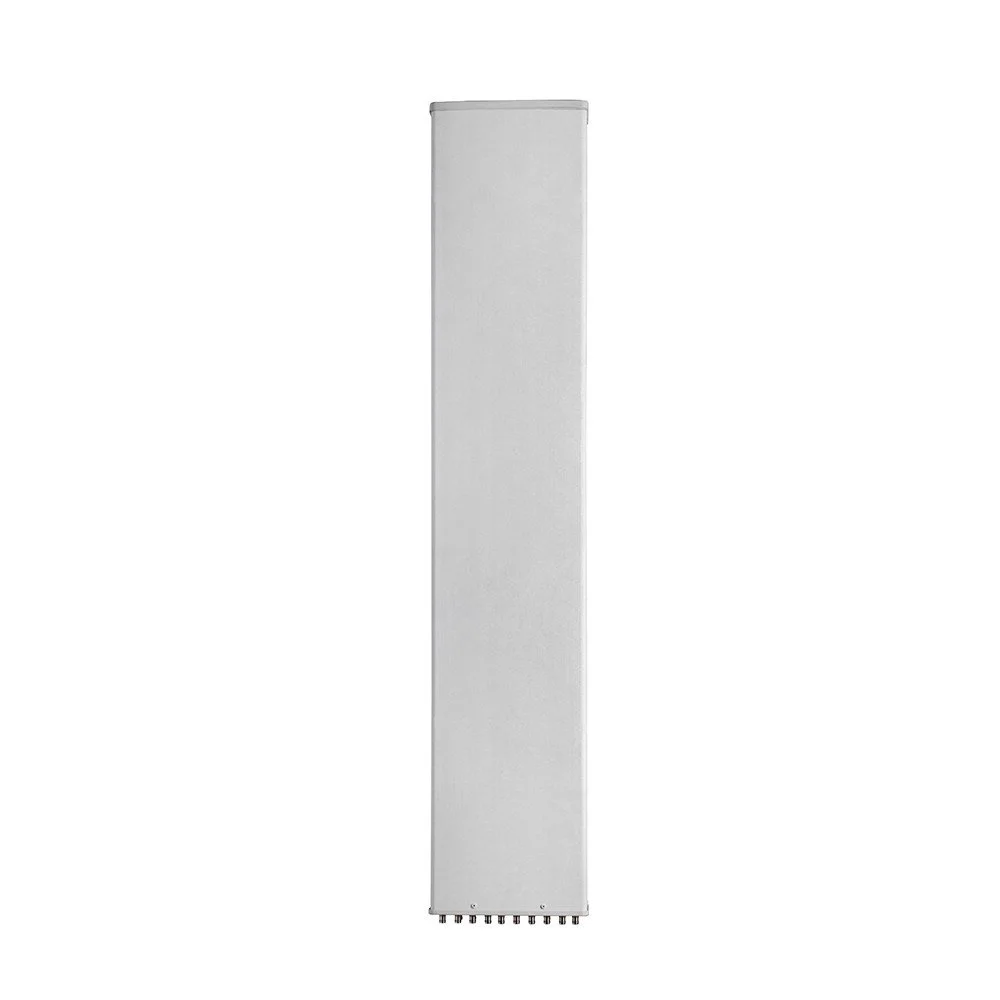
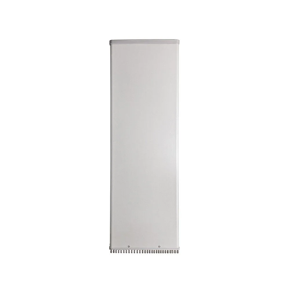
| Radome Material | Fiberglass | — |
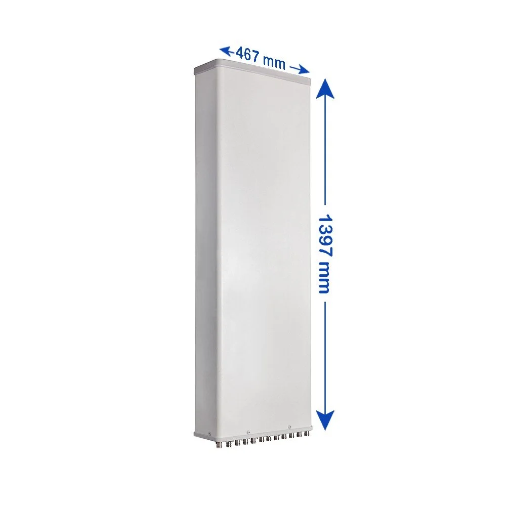
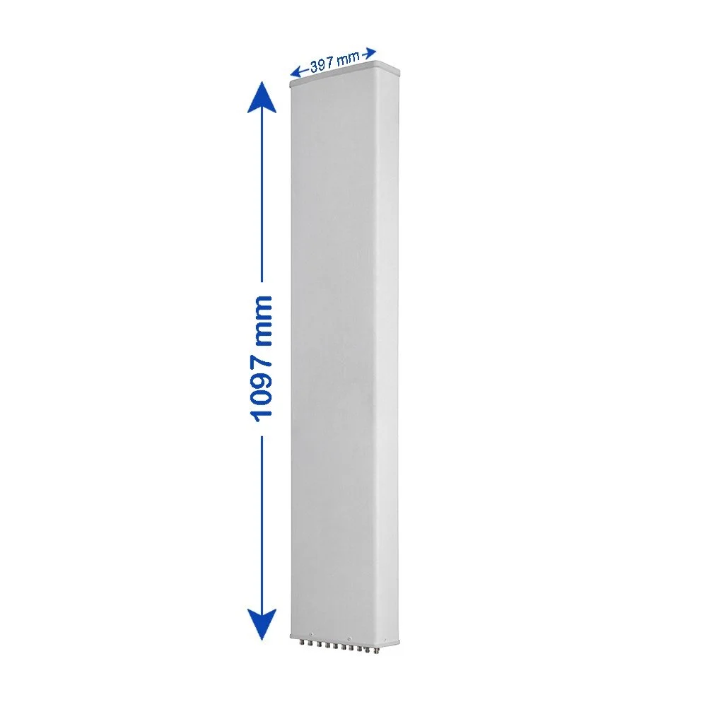
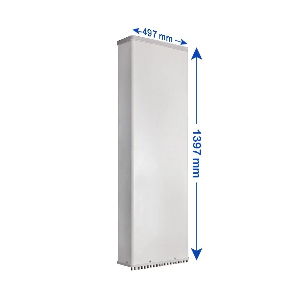
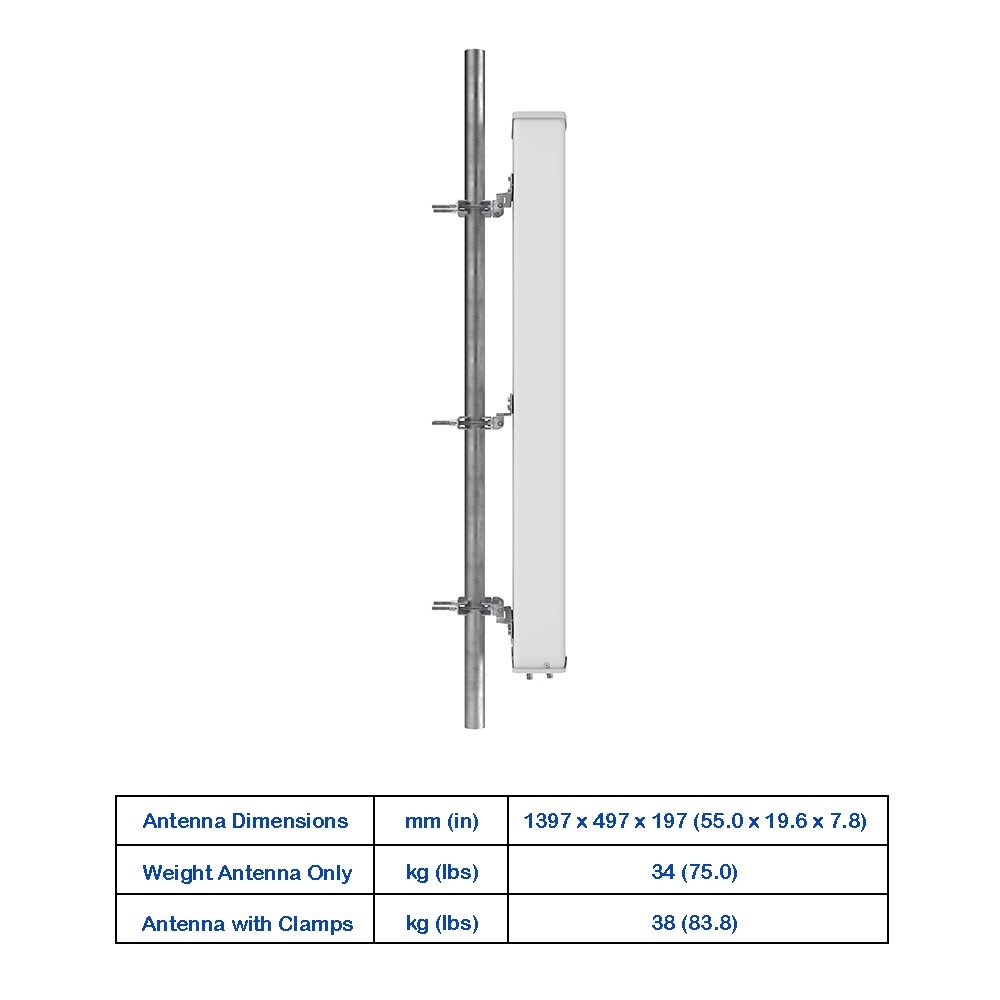
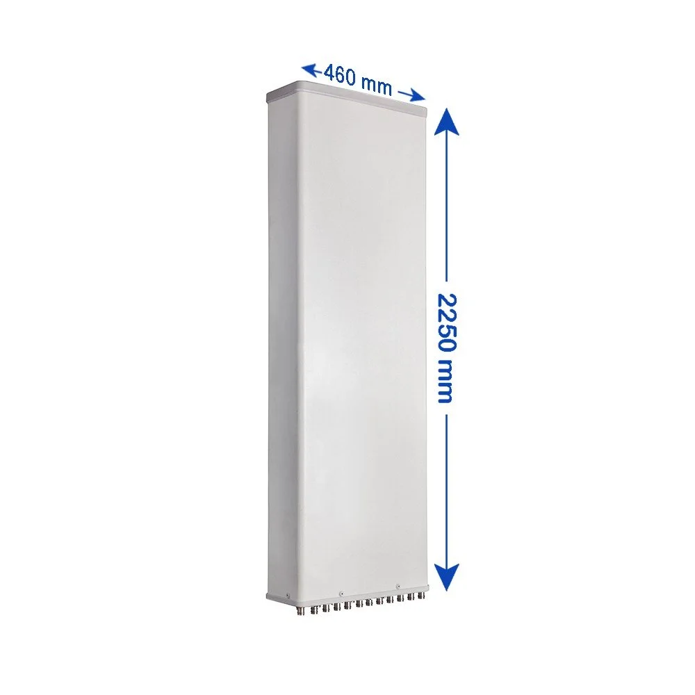
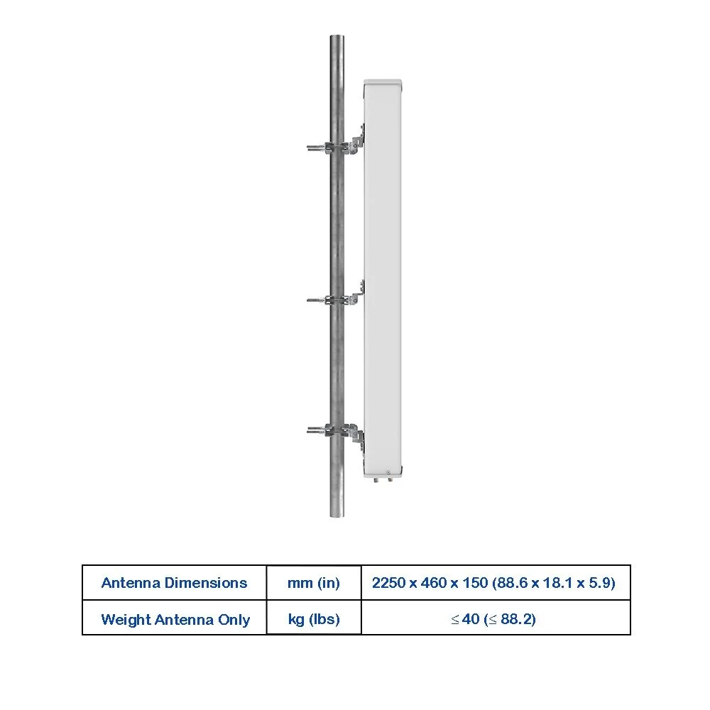
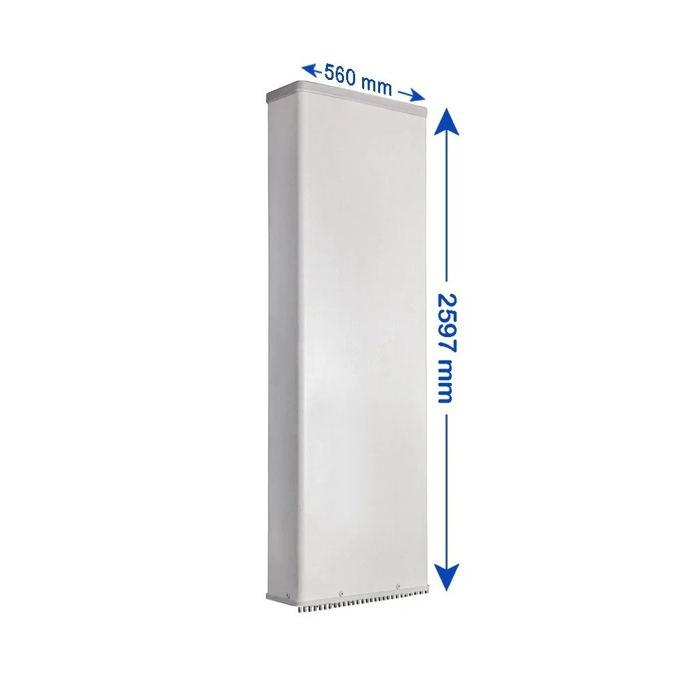
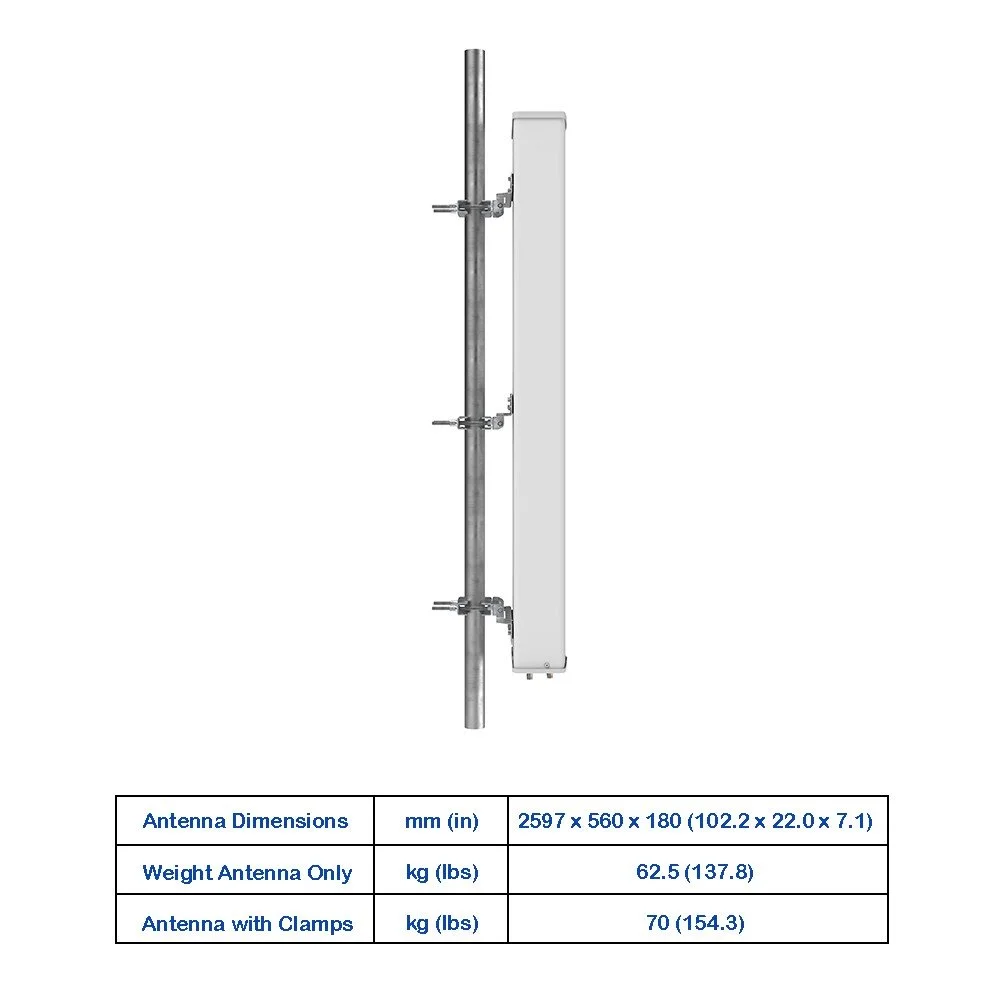
| Antenna Dimensions (H × W × D) | 1497 × 497 × 197 (58.9 × 19.6 × 7.8) | mm (in) |
| Antenna Weight – Antenna Only | 29.5 (65.0) | kg (lbs) |
| Antenna Weight – With Clamps | 35 (77.2) | kg (lbs) |
| Maximum Wind Speed | 200 (124.3) | km/h (mph) |
| Wind Load at 150 km/h – Frontal | 690 (155.1) | N (lbf) |
| Wind Load at 150 km/h – Rear | 780 (175.4) | N (lbf) |
| Wind Load at 150 km/h – Lateral | 335 (75.3) | N (lbf) |
| Operating Temperature | -40 to +60 (-40 to +140) | °C (°F) |