 Image 1 of 6
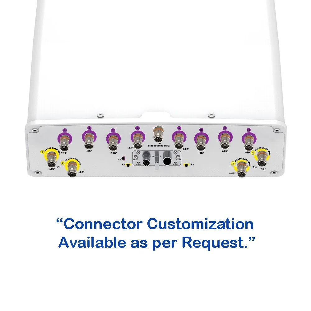 Image 2 of 6
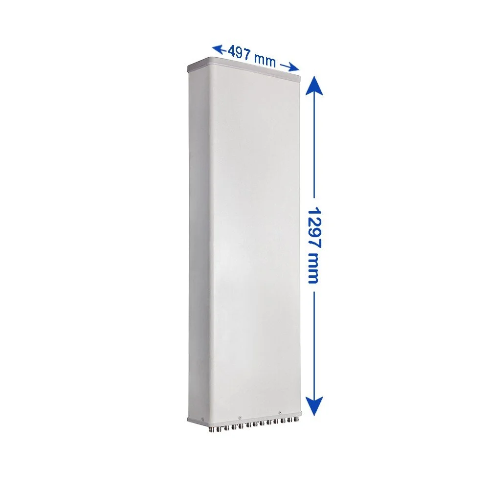 Image 3 of 6
 Image 4 of 6
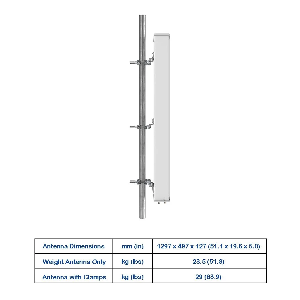 Image 5 of 6
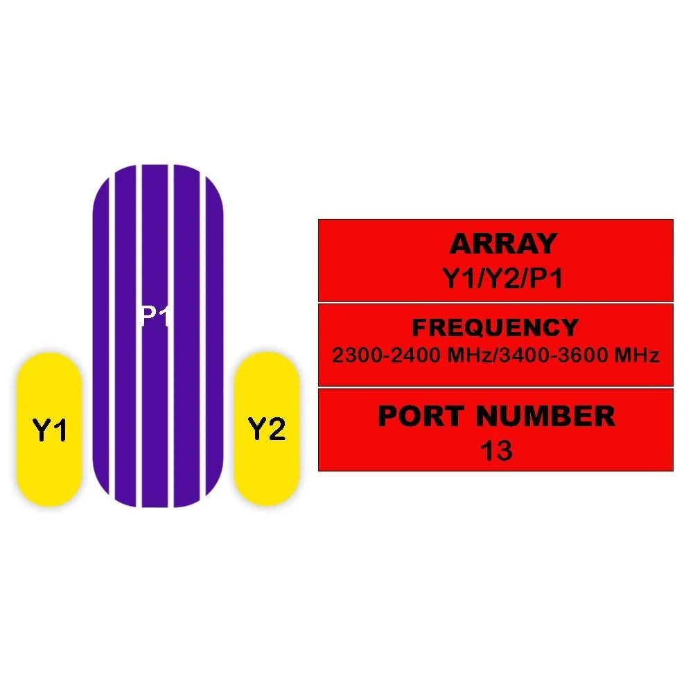 Image 6 of 6
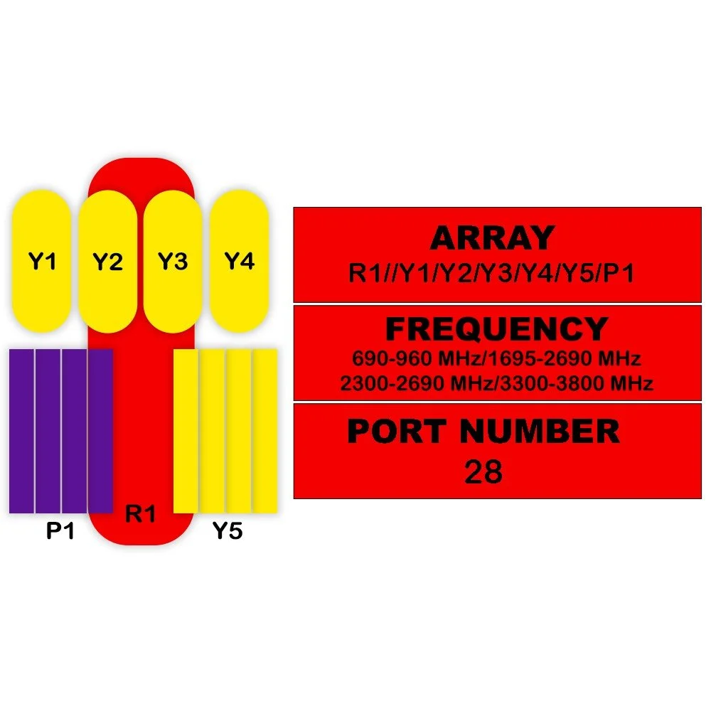
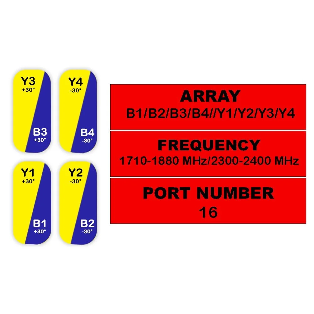
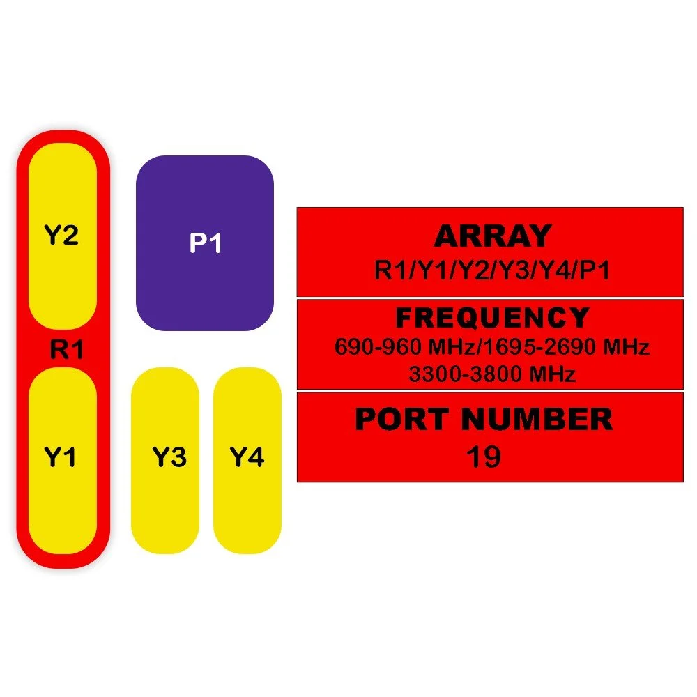
Electrical Specifications
| Parameter | Detail | Unit | Value (Y1 / Y2) |
|---|---|---|---|
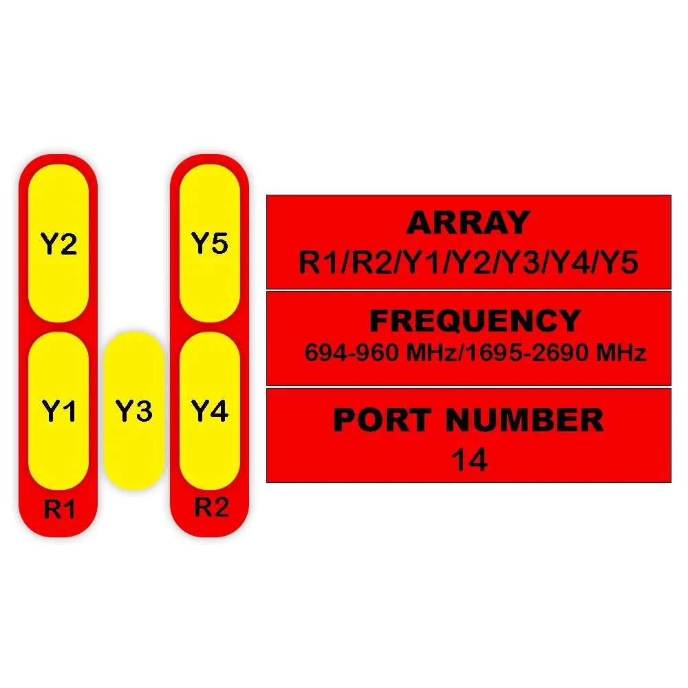
| Frequency Range | — | MHz | 2300–2400 |
| Polarization | — | — | ±45° |
| Gain | At Mid Tilt | dBi | 17.6 |
| Gain | Over All Tilts | dBi | 17.5 ± 0.5 |
| Horizontal Beamwidth | — | degree | 62 ± 5 |
| Vertical Beamwidth | — | degree | 5.9 ± 0.6 |
| Electrical Downtilt, Continuously Adjustable | — | degree | 0–10 |
| First Upper Side Lobe Suppression | — | dB | > 16 |
| Front-To-Back Ratio Co-Pol, ±30° | — | dB | > 26 |
| Cross Polar Discrimination | At Boresight | dB | > 20 |
| Cross Polar Discrimination | Over Sector | dB | > 8 |
| Isolation | Cross-Polar | dB | > 28 |
| Isolation | Intraband | dB | > 28 |
| Isolation | Interband | dB | > 28 |
| Impedance | — | Ohm | 50 |
| VSWR | — | — | < 1.5 |
| Return Loss | — | dB | > 14 |
| PIM3 (2×43 dBm Carrier) | — | dBc | < -150 |
| Lightning Protection | — | — | DC Ground |
| Maximum Average Input Power Per Port, At 50° C Ambient Temperature |
— | Watts | 250 |
Electrical Specifications (P1)
| Category | Parameter | Unit | Value |
|---|---|---|---|
| Frequency Range | — | MHz | 3400–3600 |
| Polarization | — | — | ±45° |
| Electrical Downtilt | — | degree | 2–12 |
| Single Column Beam | |||
| Gain | dBi | 15.6 ± 1 | |
| Horizontal Beamwidth | degree | 75 ± 10 | |
| Vertical Beamwidth (3 dB) | degree | 5.6 ± 0.6 | |
| Cross Polar Discrimination At Boresight | dB | ≥ 15 | |
| First Upper Side Lobe Suppression | dB | ≥ 15 | |
| Front-To-Back Ratio | dB | ≥ 25 | |
| Broadcast Beam (65°) | |||
| Gain of Broadcasting Pattern (Typical) | dBi | 17.1 ± 0.6 | |
| Horizontal Beamwidth | degree | 65 | |
| Vertical Beamwidth (3 dB) | degree | 5.6 ± 0.6 | |
| Cross Polar Discrimination At Boresight | dB | ≥ 15 | |
| First Upper Side Lobe Suppression | dB | ≥ 15 | |
| Front-To-Back Ratio | dB | ≥ 27 | |
| Service Beam (0°) | |||
| 0° Direct Beam Gain | dBi | 21.1 ± 0.5 | |
| 0° Direct Beam Horizontal 3 dB Beamwidth | degree | < 25 | |
| ±30° Direct Beam Gain | dBi | 18.1 | |
| ±30° Direct Beam Horizontal 3 dB Beamwidth | degree | < 30 | |
| 0° Direct Beam Cross Polar Ratio | dB | ≥ 18 | |
| 0° Direct Beam Front-To-Back Ratio | dB | ≥ 30 | |
| Calibration & Electrical Parameters | |||
| Coupling Factor Between Calibration And Each Antenna Port | dB | -26 ± 2 | |
| Max. Amplitude Tolerance From Calibration Port To Input Ports | dB | ≤ 0.7 | |
| Max. Phase Tolerance From Calibration Port To Input Ports | degree | ≤ 9 | |
| Average Power Per Port | W | 25 | |
| Isolation | Co-Polar Isolation Between Ports | dB | ≥ 20 |
| Cross-Polar Isolation Between Ports | dB | ≥ 25 | |
| Impedance | — | Ohm | 50 |
| VSWR | — | — | < 1.5 |
| Return Loss | — | dB | > 14 |
| Lightning Protection | — | — | DC Ground |
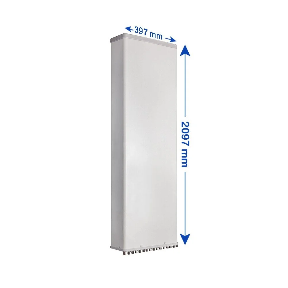
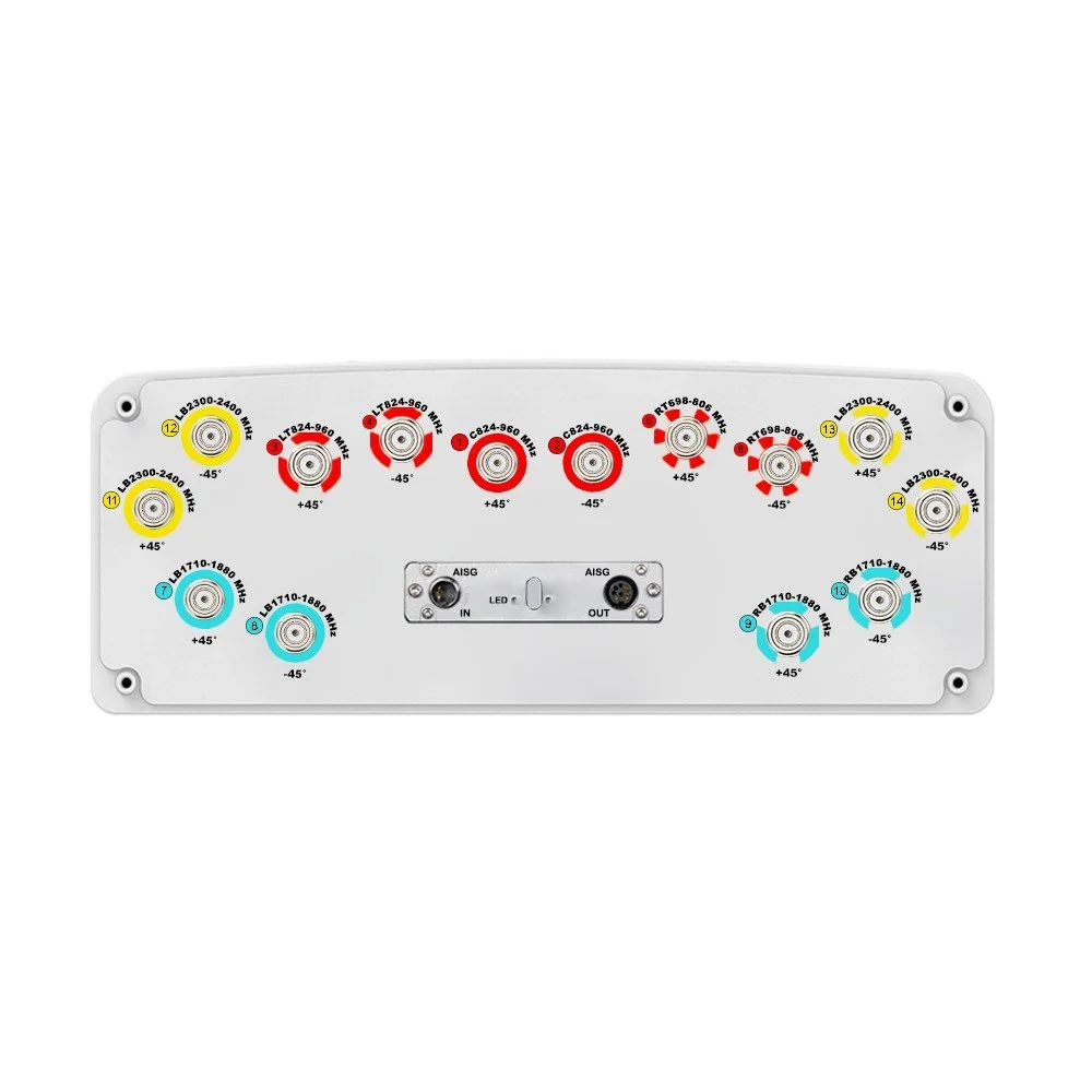
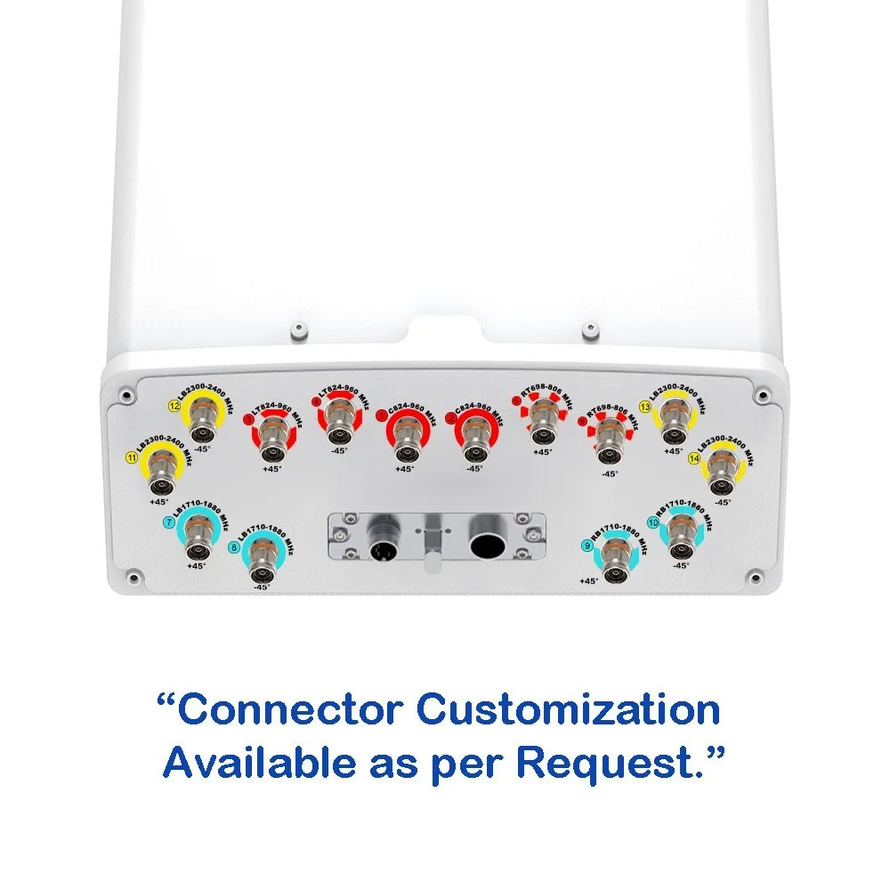
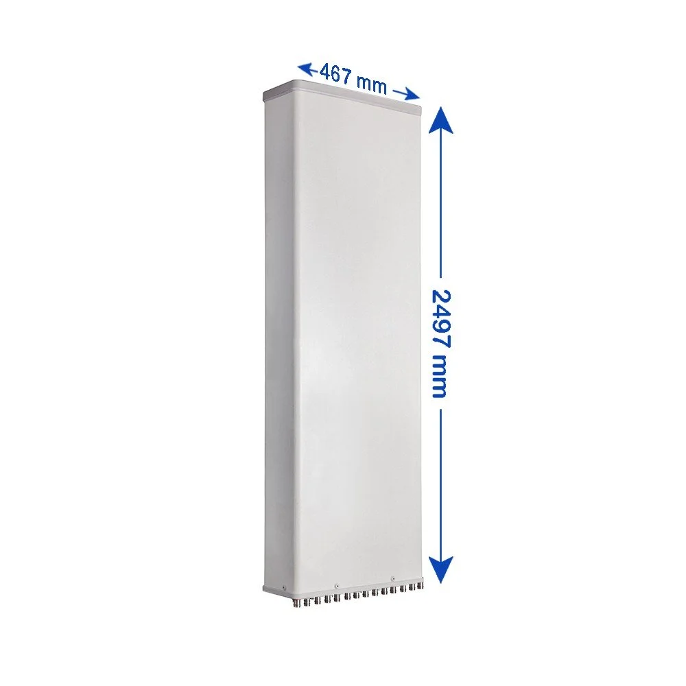
Mechanical Specifications
| Parameter | Detail | Unit | Value |
|---|---|---|---|
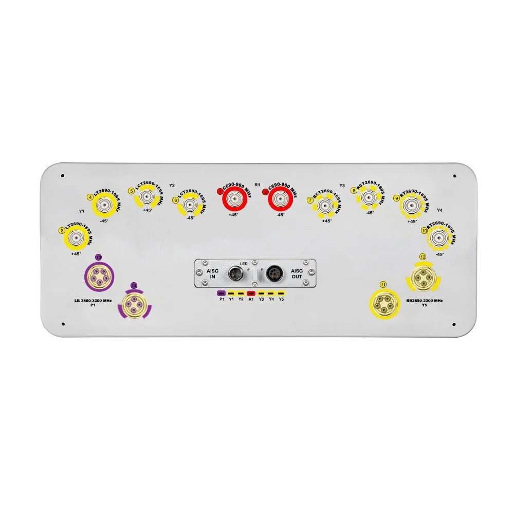
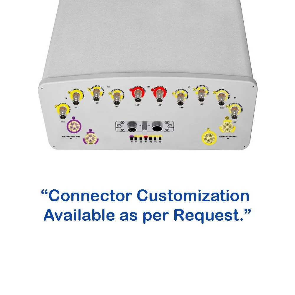
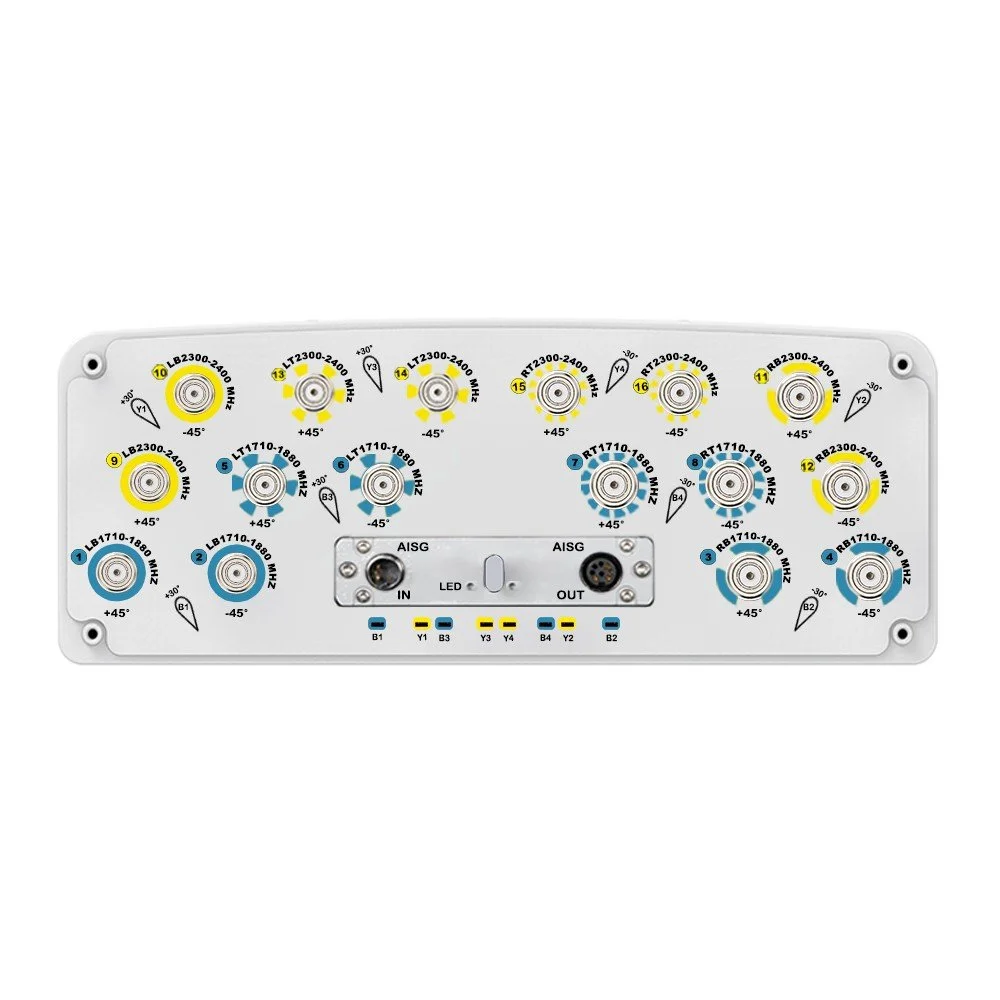
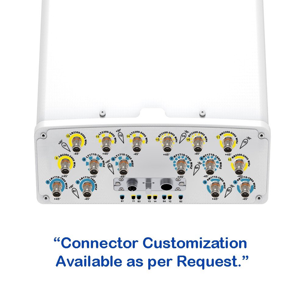
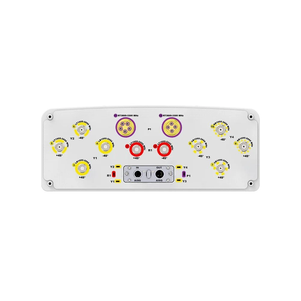
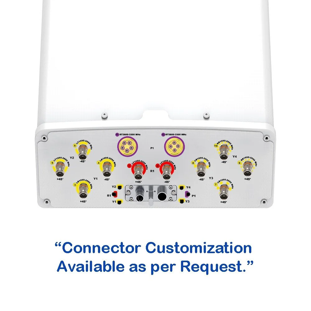
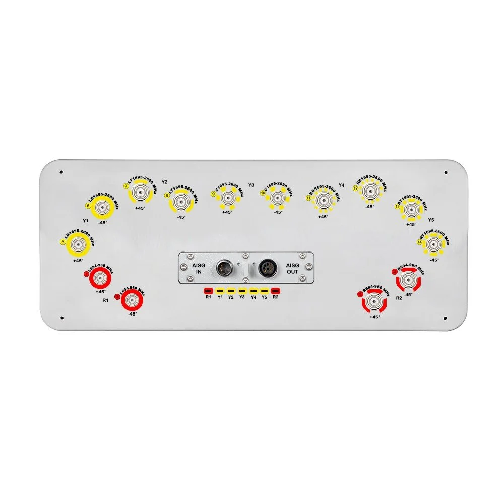
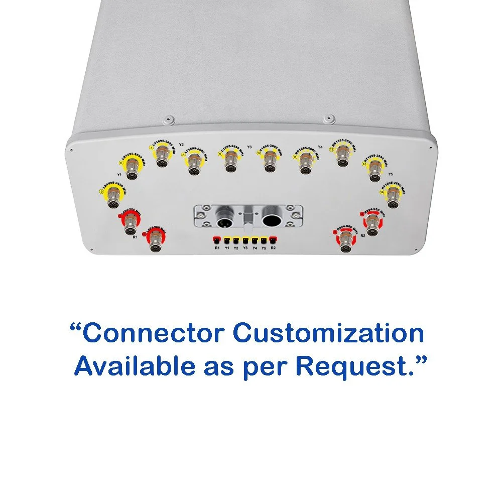
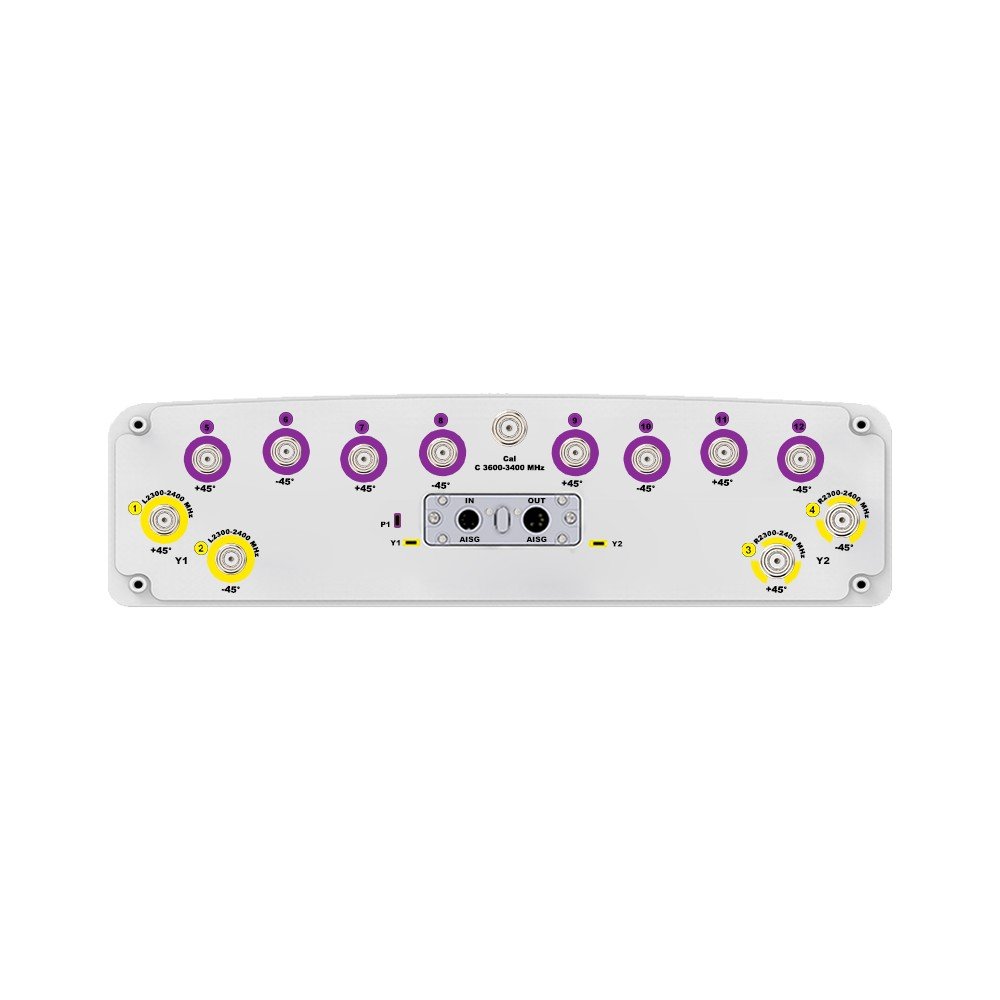
| Connector Type | — | — | (13×) 4.3/10 Female |
| Connector Position | — | — | Bottom |
| Electrical Tilt Control | — | — | Integrated RET |
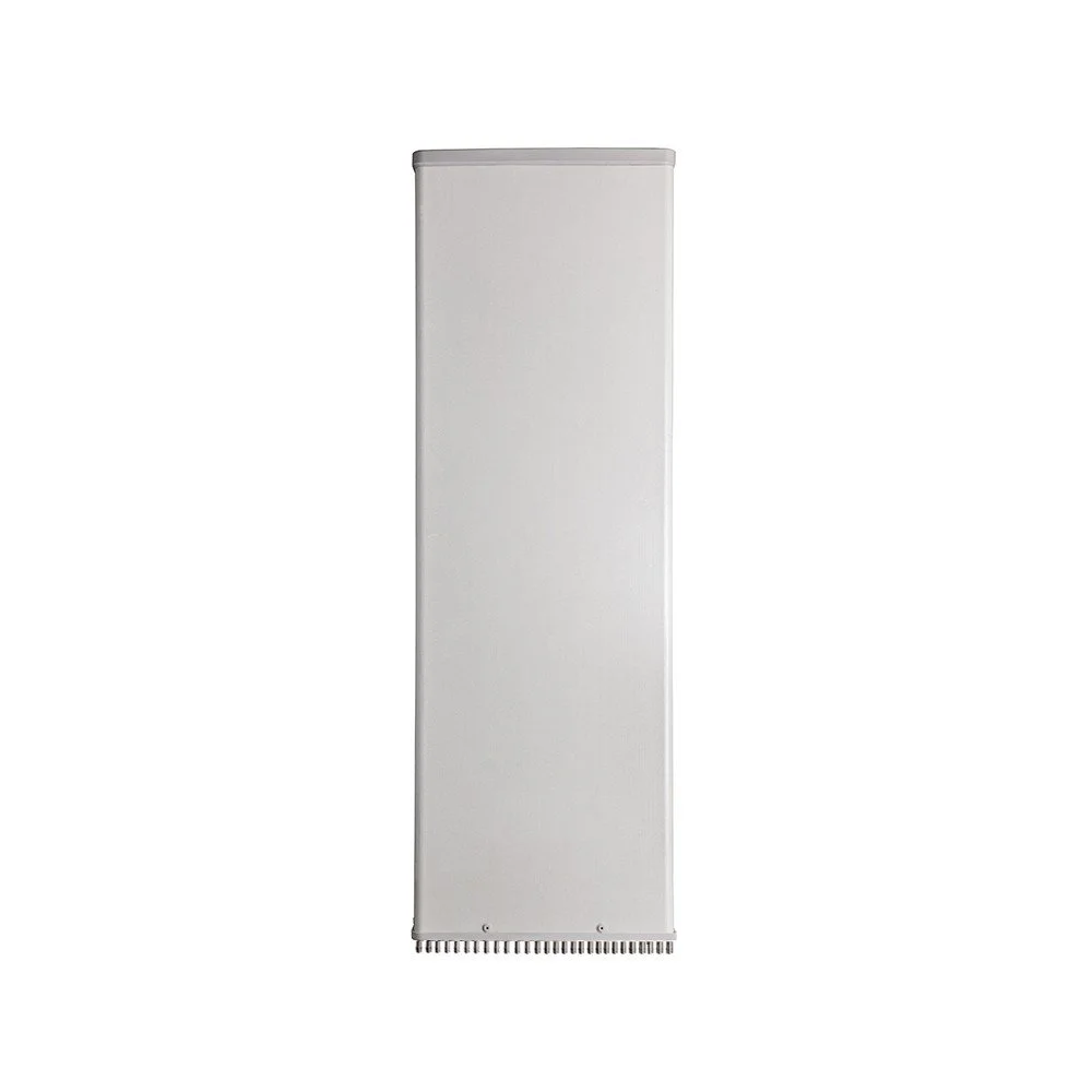
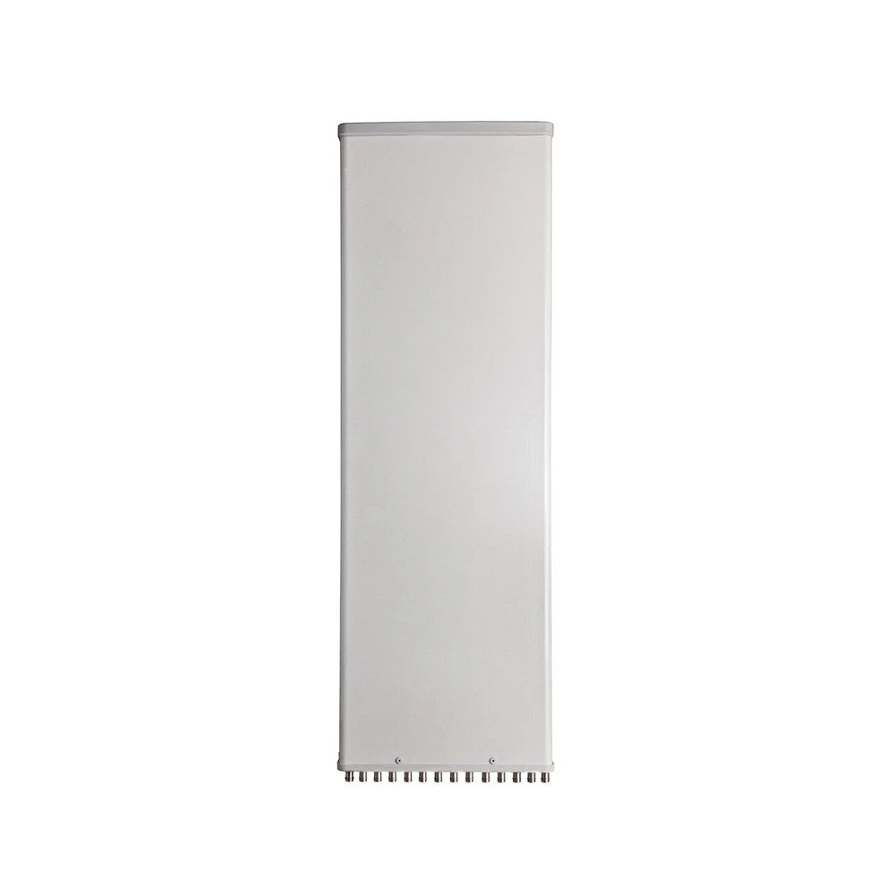
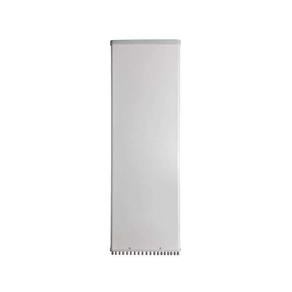
| Radome Material | — | — | Fiberglass |
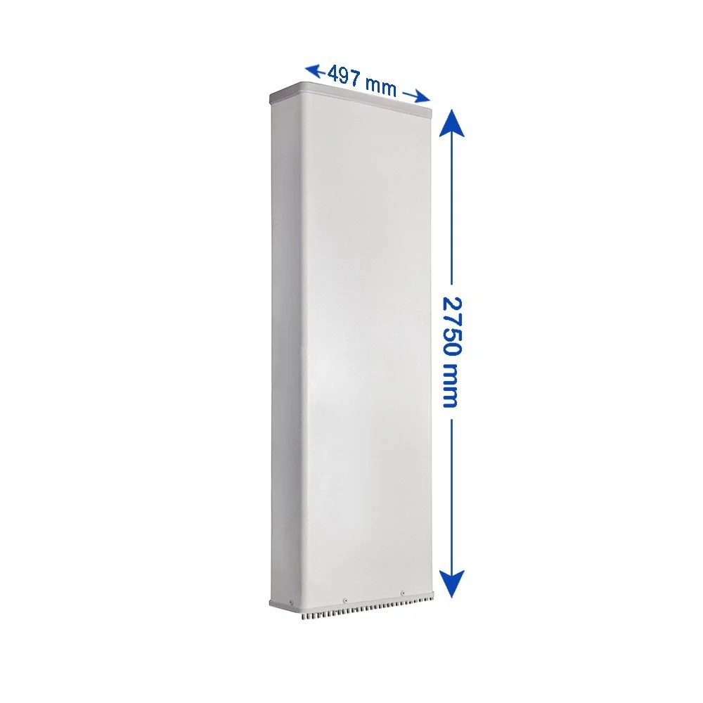
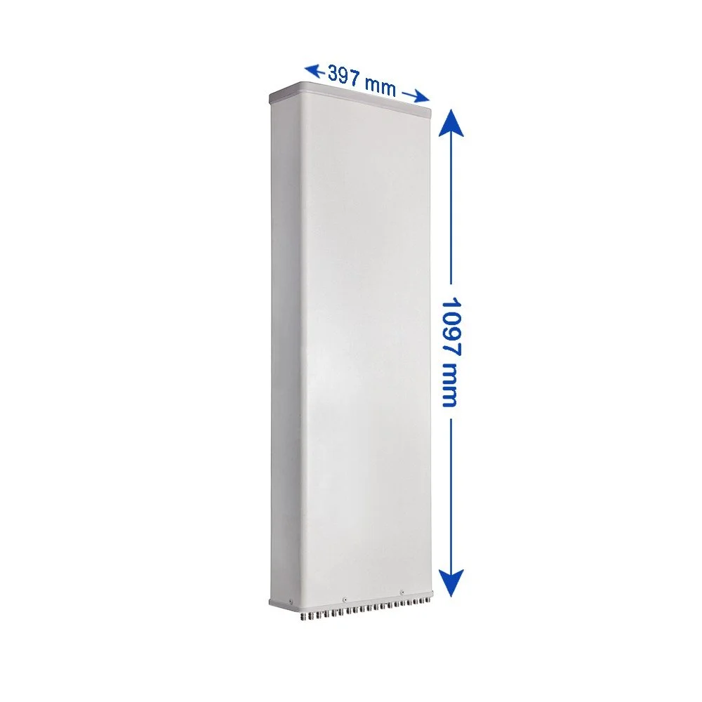
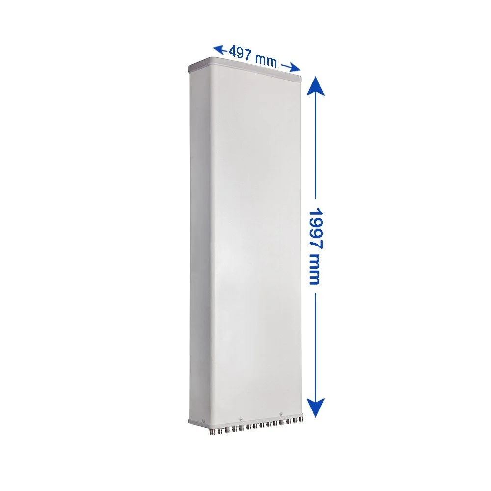
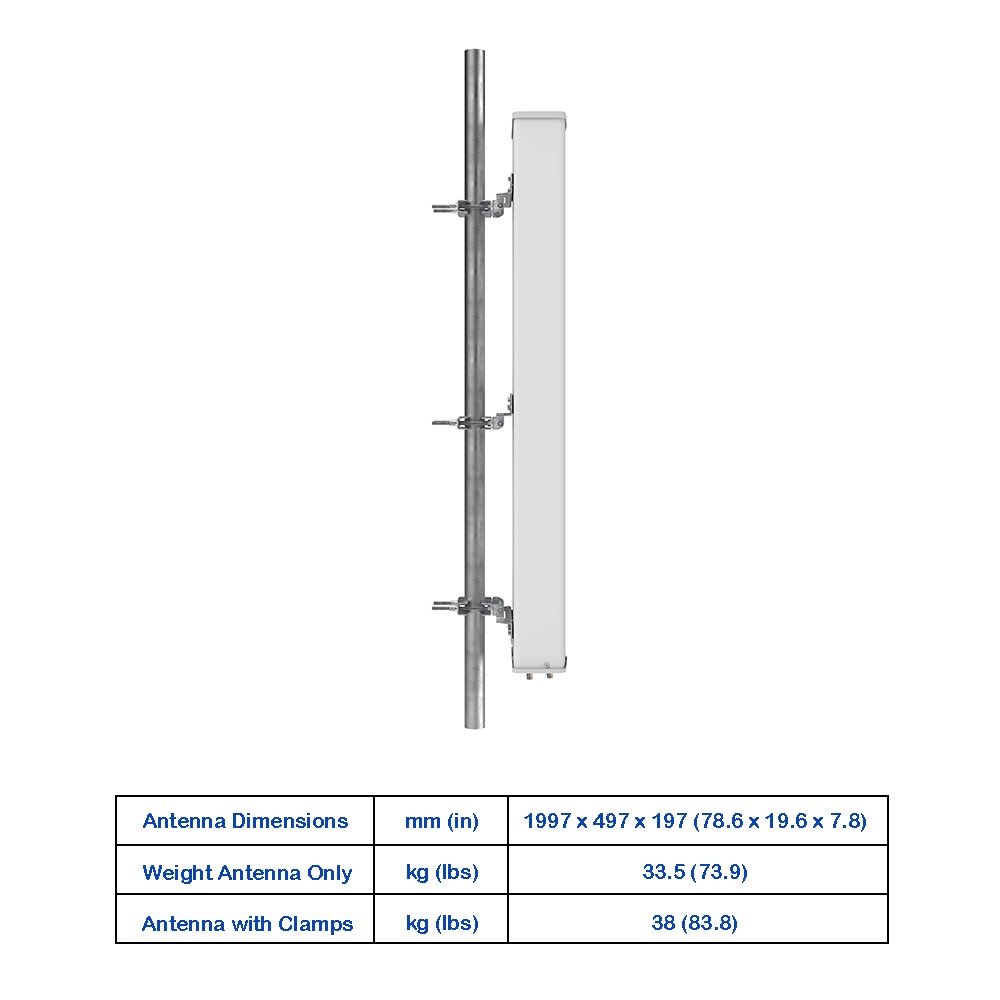
| Antenna Dimensions (H × W × D) | — | mm (in) | 1297 × 497 × 127 (51.1 × 19.6 × 5.0) |
| Antenna Weight | Antenna Only | kg (lbs) | 23.5 (51.8) |
| Antenna Weight | With Clamps | kg (lbs) | 29 (63.9) |
| Maximum Wind Speed | — | km/h (mph) | 200 (124.3) |
| Wind Load at 150 km/h | Frontal | N (lbf) | 595 (133.8) |
| Wind Load at 150 km/h | Rear | N (lbf) | 665 (149.5) |
| Wind Load at 150 km/h | Lateral | N (lbf) | 190 (42.7) |