 Image 1 of 6
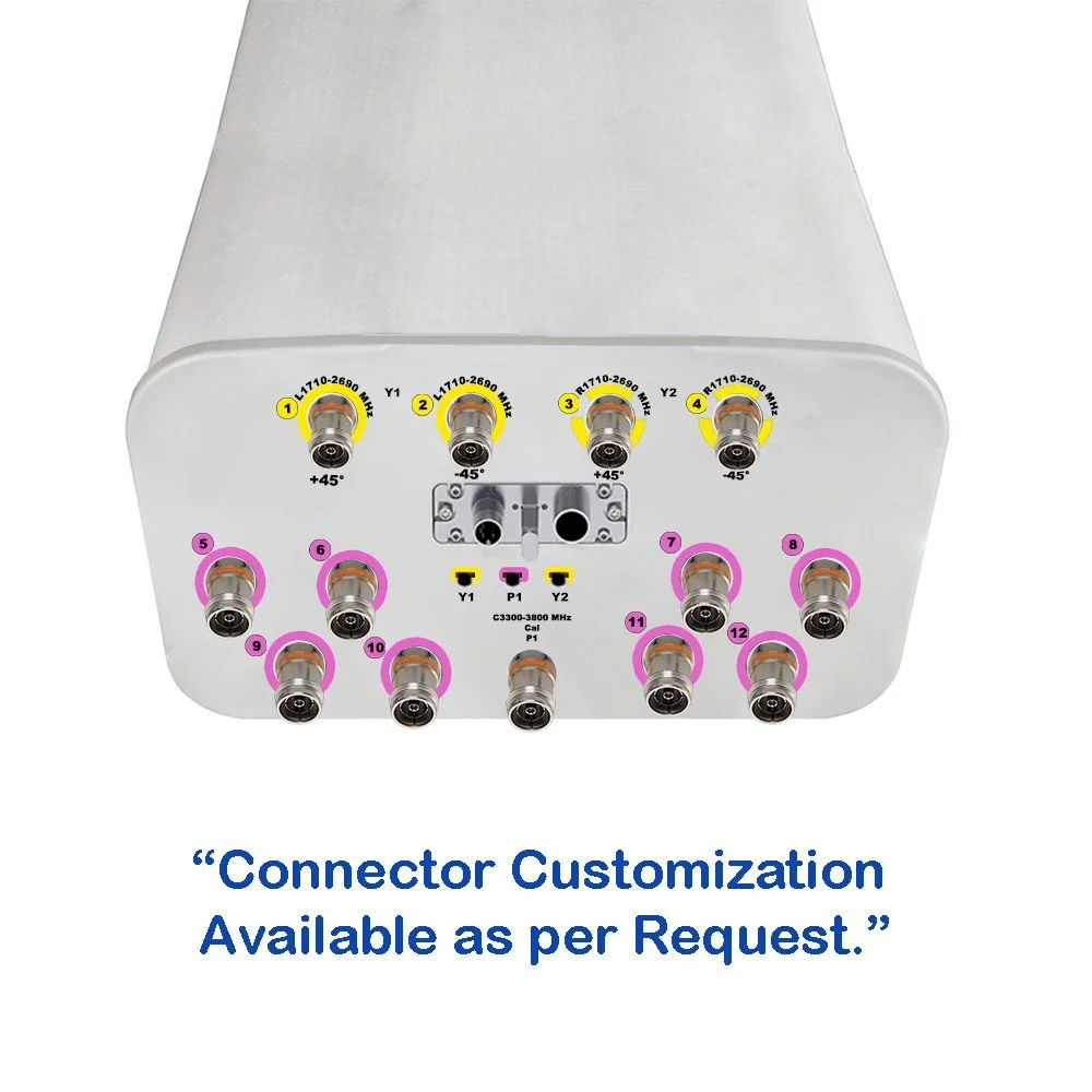 Image 2 of 6
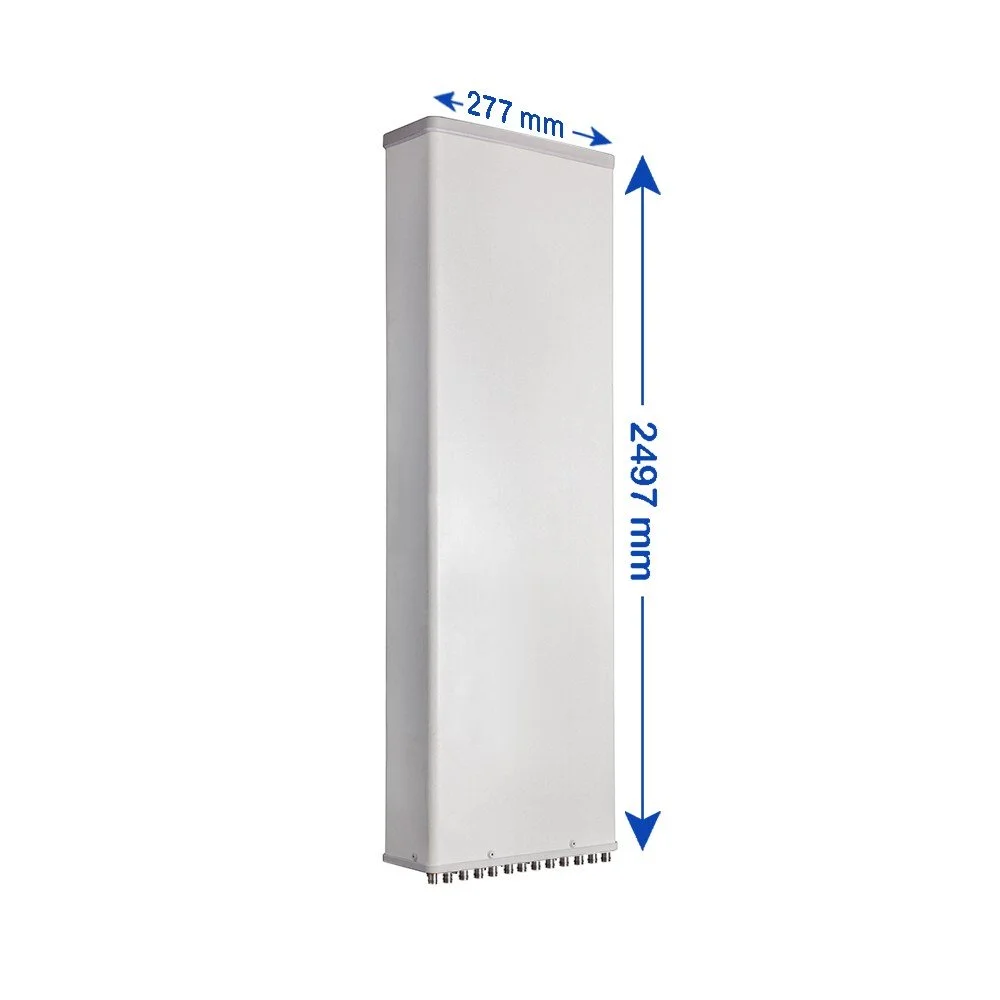 Image 3 of 6
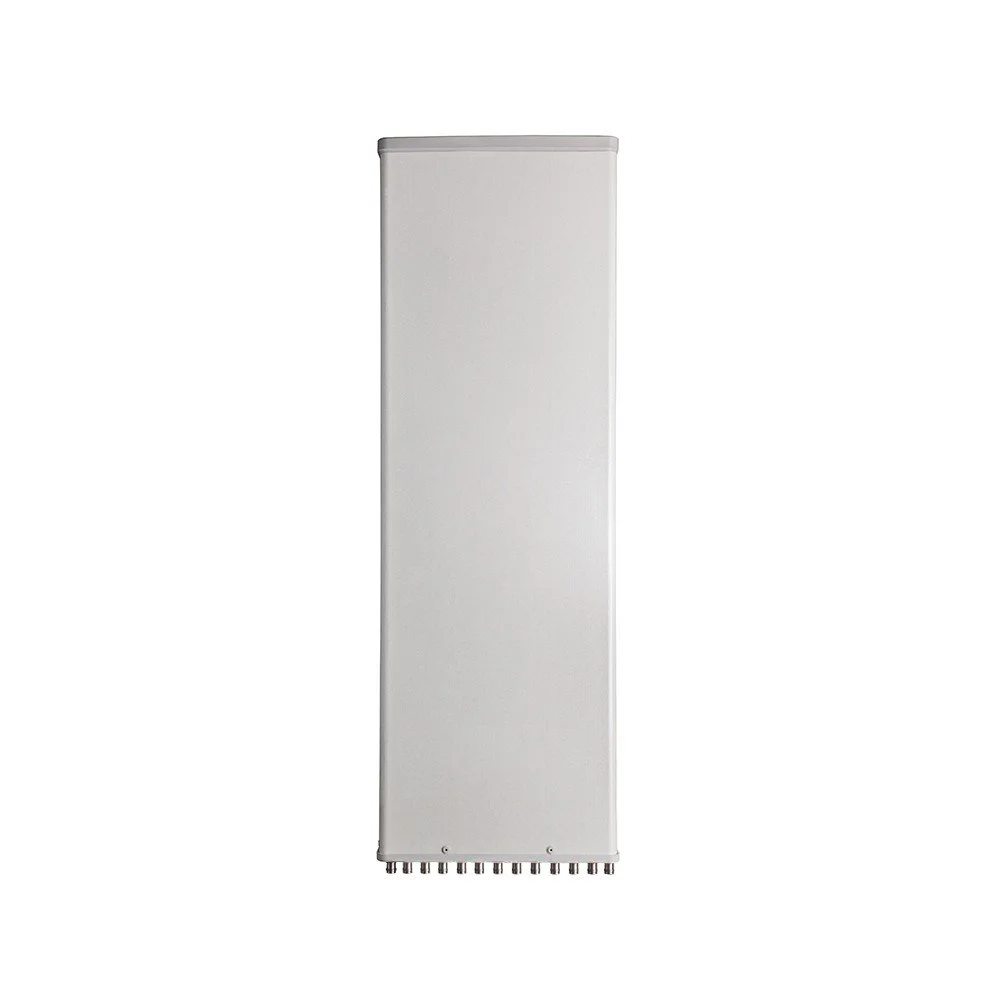 Image 4 of 6
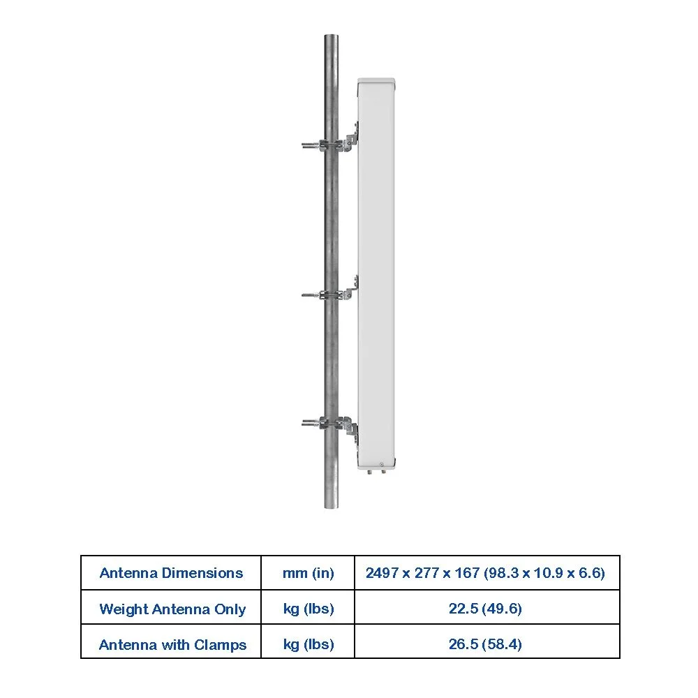 Image 5 of 6
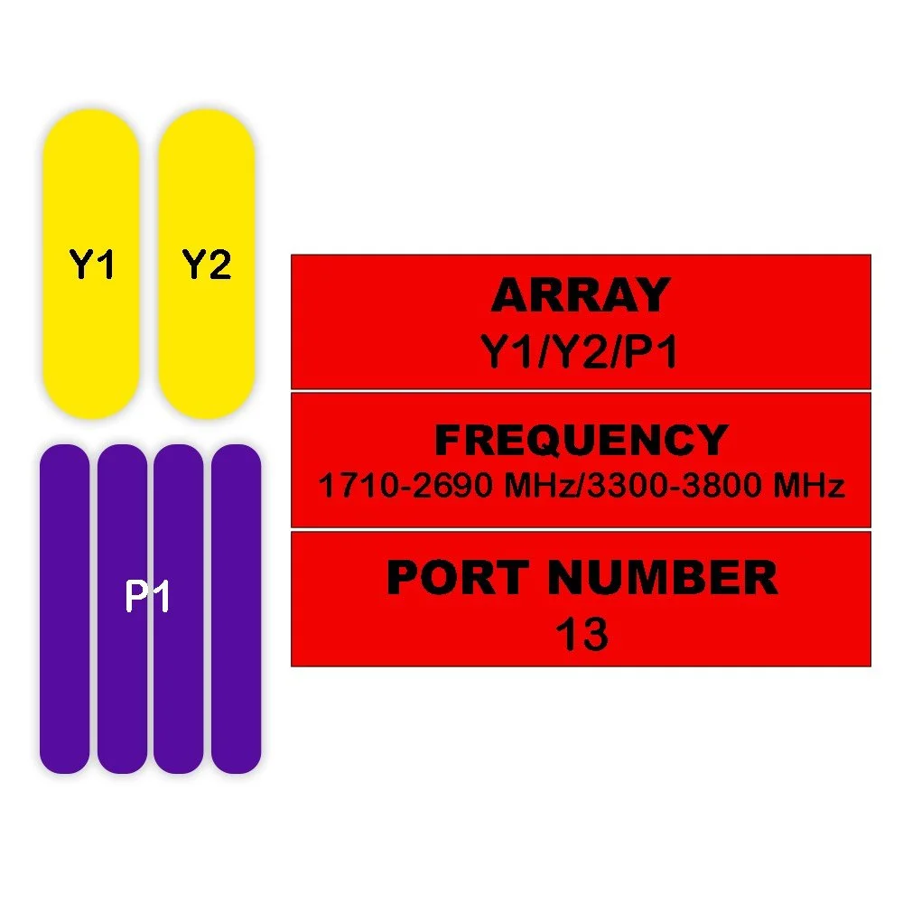 Image 6 of 6
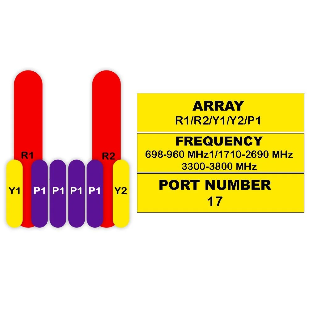
Electrical Specifications
| Parameter | Sub-Parameter | Unit | 1710–1880 | 1850–1990 | 1920–2170 | 2300–2400 | 2490–2690 |
|---|---|---|---|---|---|---|---|
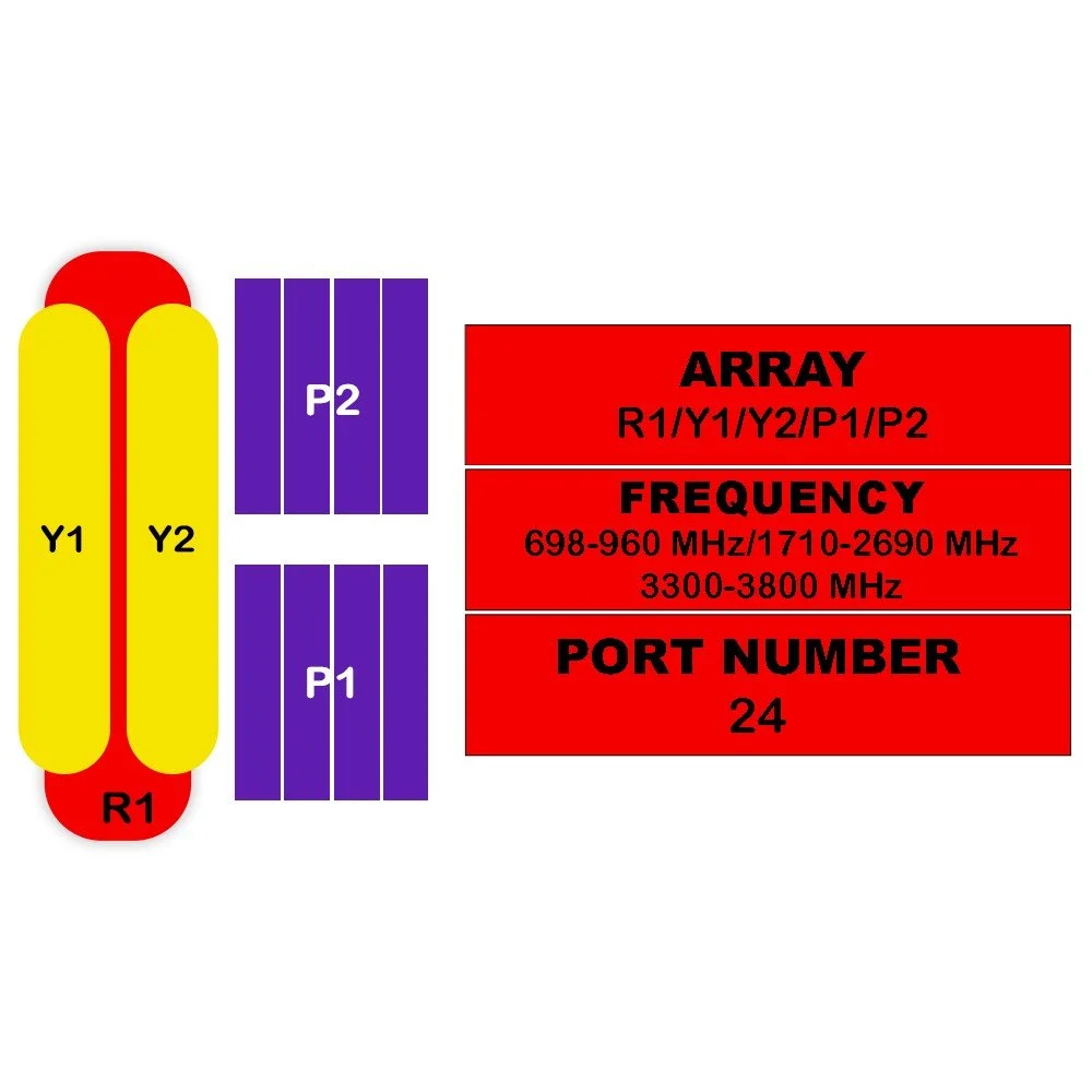
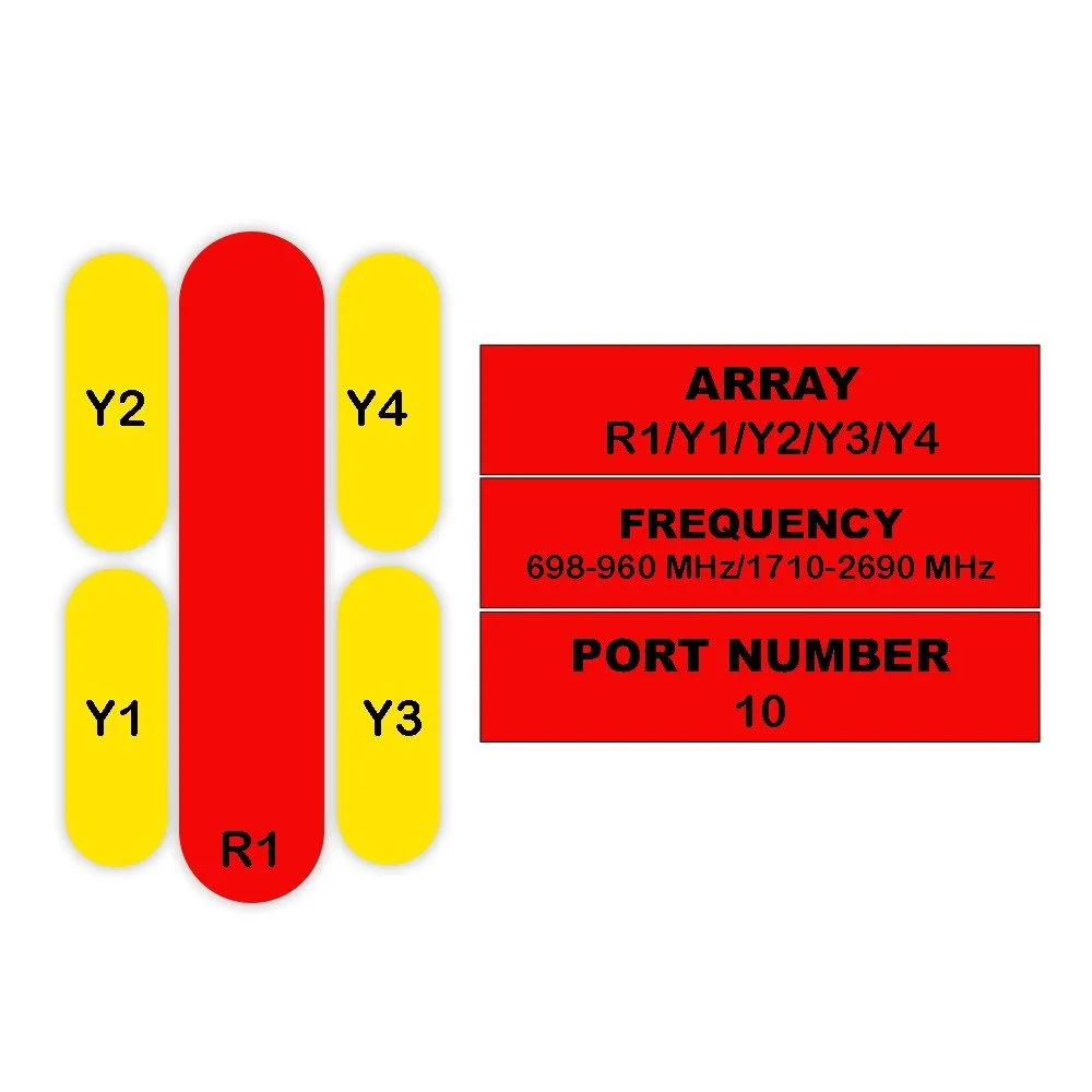
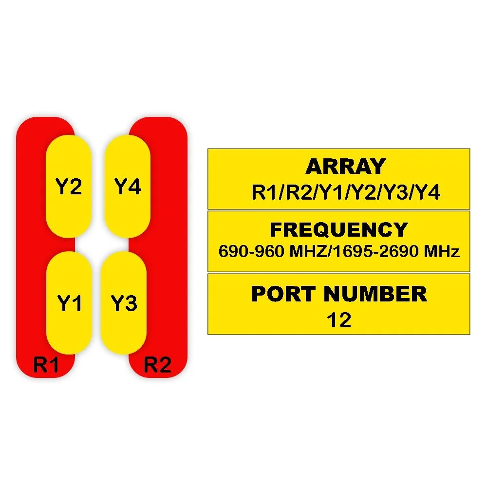
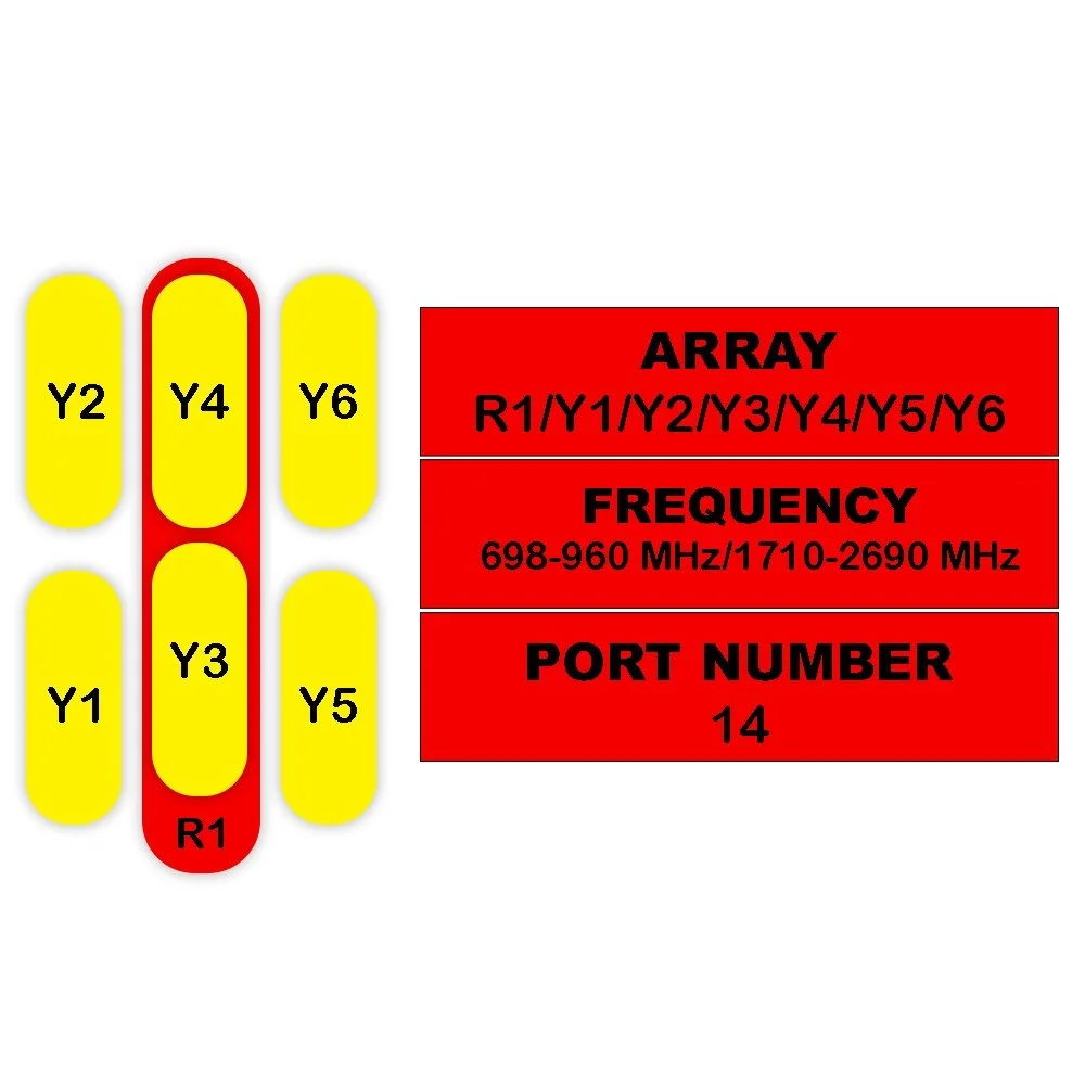
| Frequency Range | Y1 / Y2 | MHz | 1710–2690 | ||||
| Polarization | — | — | ±45° | ||||
| Gain | At Mid Tilt | dBi | 17.1 | 17.3 | 17.5 | 17.9 | 17.7 |
| Over All Tilts | dBi | 17.0 ± 0.5 | 17.2 ± 0.5 | 17.4 ± 0.5 | 17.8 ± 0.5 | 17.6 ± 0.6 | |
| Horizontal Beamwidth | — | degree | 67 ± 5 | 65 ± 5 | 63 ± 5 | 61 ± 5 | 58 ± 5 |
| Vertical Beamwidth | — | degree | 7.0 ± 0.7 | 6.7 ± 0.6 | 6.3 ± 0.6 | 5.4 ± 0.5 | 5.0 ± 0.4 |
| Electrical Downtilt, Continuously Adjustable | — | degree | 0–10 | ||||
| First Upper Side Lobe Suppression | — | dB | > 16 | > 16 | > 16 | > 16 | > 16 |
| Front-To-Back Ratio, ±30° | — | dB | > 25 | > 25 | > 25 | > 25 | > 25 |
| Cross Polar Discrimination | At Boresight | dB | > 20 | > 20 | > 20 | > 20 | > 20 |
| Over Sector | dB | > 10 | > 10 | > 10 | > 9 | > 8 | |
| Isolation | Cross-Polar | dB | > 28 | ||||
| Port-to-Port | dB | > 28 | |||||
| Impedance | — | Ohm | 50 | ||||
| VSWR | — | — | < 1.5 | ||||
| Return Loss | — | dB | > 14 | ||||
| PIM3 (2x43 dBm Carrier) | — | dBc | < -150 | ||||
| Lightning Protection | — | — | DC Ground | ||||
| Maximum Average Input Power per Port, at 50° C Ambient Temperature | — | Watts | 200 | ||||
| Category | Parameter | Sub-Parameter | Unit | Value (P1) |
|---|---|---|---|---|
| TDD LTE Electrical Specifications — P1 | ||||
| General | Frequency Range | MHz | 3300–3800 | |
| General | Polarization | — | ±45° | |
| General | Electrical Downtilt (Continuously Adjustable) | degree | 2–12 | |
| Single Column Beam | ||||
| Gain | dBi | 17 | ||
| Horizontal Beamwidth | degree | 75 | ||
| Vertical Beamwidth (3 dB) | degree | 5.8 | ||
| Cross-Polar Discrimination | At Boresight (0°) | dB | ≥ 15 | |
| Cross-Polar Discrimination | Over Sector | dB | ≥ 8 | |
| First Upper Side Lobe Suppression | dB | ≥ 15 | ||
| Front-To-Back Ratio | dB | ≥ 23 | ||
| 65° Broadcast Beam | ||||
| Gain | dB | 18 | ||
| Horizontal Beamwidth | degree | 65 | ||
| Vertical Beamwidth (3 dB) | degree | 5.8 | ||
| Cross-Polar Discrimination (0°) | dB | ≥ 15 | ||
| First Upper Side Lobe Suppression | dB | ≥ 15 | ||
| Front-To-Back Ratio | dB | ≥ 25 | ||
| Service Beam | ||||
| 0° Direct Beam Gain | dBi | 21.5 | ||
| 0° Direct Beam Horizontal 3 dB Beamwidth | degree | 26 | ||
| 0° Direct Beam Cross-Polar Ratio at Beampeak | dB | ≥ 16 | ||
| 0° Direct Beam Front-To-Back Ratio | dB | ≥ 27 | ||
| 0° Direct Beam Horizontal Sidelobe | dB | 12 | ||
| ±30° Direction Beam Gain | dBi | 20 | ||
| ±30° Direction Beam Horizontal 3 dB Beamwidth | degree | 31 | ||
| ±30° Direction Beam Front-To-Back Ratio | dB | ≥ 25 | ||
| Soft Split Multi-Beam | ||||
| Gain | dBi | 20 | ||
| Horizontal Beamwidth (3 dB) | degree | 31 | ||
| Front-To-Back Ratio | dB | ≥ 25 | ||
| Calibration & Electrical Parameters | ||||
| Coupling Factor Between Calibration and Each Antenna Port | dB | -26 ± 2 | ||
| Maximum Amplitude Tolerance From Calibration Port to Input Ports | dB | ≤ 1.0 | ||
| Maximum Phase Tolerance From Calibration Port to Input Ports | degree | ≤ 9 | ||
| Ports VSWR | — | < 1.5 | ||
| Average Power Capacity | W | 25 | ||
| Co-Polar Isolation Between Ports | dB | ≥ 23 | ||
| Inter-band Isolation | dB | ≥ 23 | ||
| General | Impedance | Ohms | 50 | |
| General | Lightning Protection | DC Ground | ||
| Category | Parameter | Sub-Parameter | Unit | Value (P1) |
|---|---|---|---|---|
| 5G NR Electrical Specifications — P1 | ||||
| General | Frequency Range | MHz | 3300–3800 | |
| Single Column Beam | ||||
| Gain | dBi | 17 | ||
| Horizontal Beamwidth | degree | 75 | ||
| Vertical Beamwidth (3 dB) | degree | 5.8 | ||
| Cross-Polar Discrimination | At Boresight (0°) | dB | ≥ 15 | |
| Cross-Polar Discrimination | Over Sector | dB | ≥ 8 | |
| First Upper Side Lobe Suppression | dB | ≥ 15 | ||
| NR Broadcast Beam (±13°, ±43° Service Beam) | ||||
| Gain | dB | 21 | ||
| Horizontal Beamwidth (10 dB) | degree | 120 | ||
| Vertical Beamwidth | degree | 5.8 | ||
| First Upper Side Lobe Suppression | dB | ≥ 15 | ||
| Front-To-Back Ratio | dB | ≥ 25 | ||
| NR Service Beam | ||||
| 0° Direct Beam Gain | dBi | 21.5 | ||
| 0° Direct Beam Horizontal 3 dB Beamwidth | degree | 26 | ||
| 0° Direct Beam Cross-Polar Ratio | At Beampeak | dB | ≥ 16 | |
| 0° Direct Beam Front-To-Back Ratio | dB | ≥ 27 | ||
| 0° Direct Beam Horizontal Sidelobe | dB | 12 | ||
| Parameter | Sub-Parameter | Unit | Value |
|---|---|---|---|
| Mechanical Specifications | |||
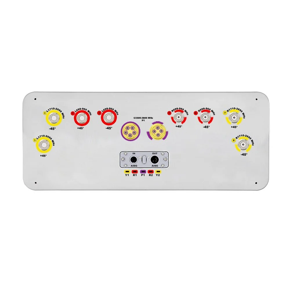
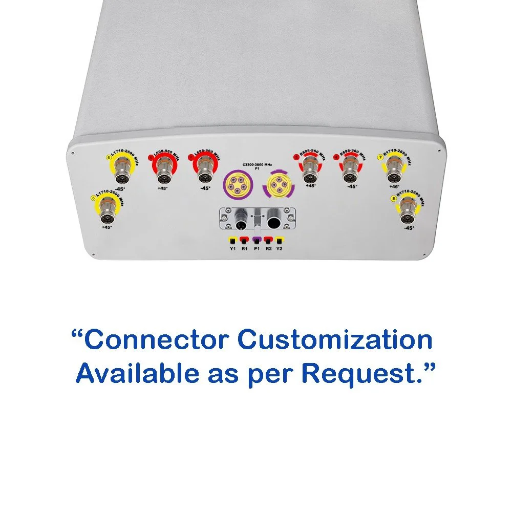
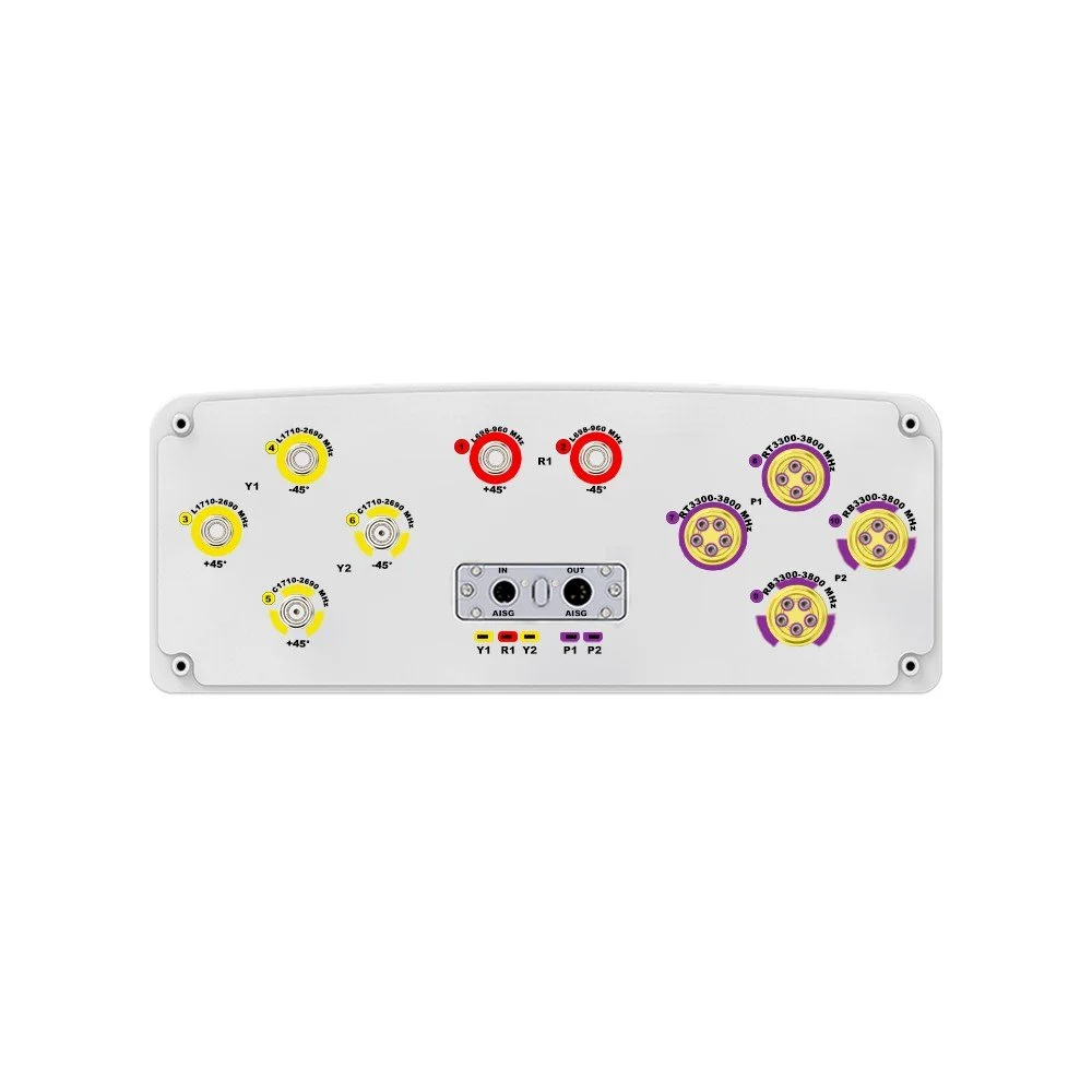
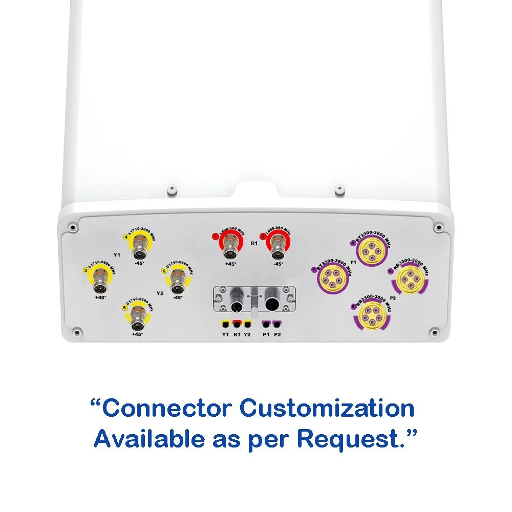
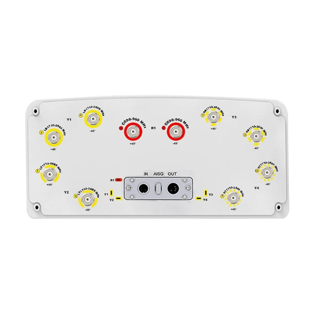
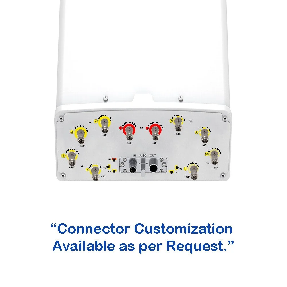
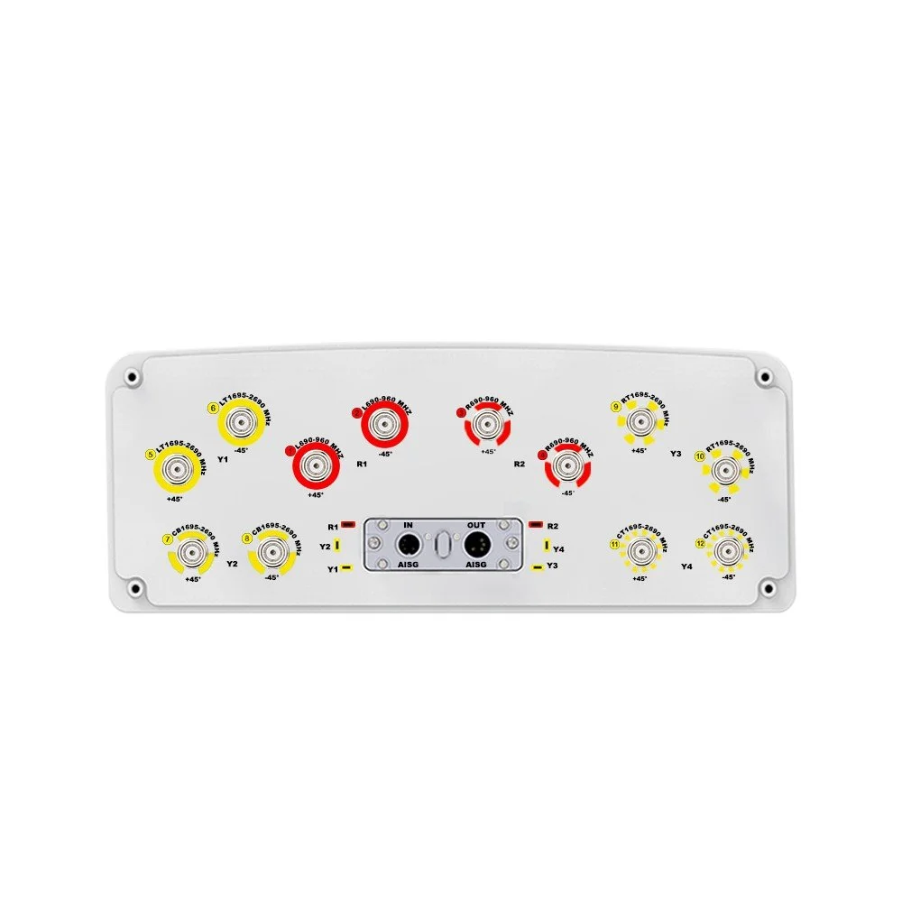
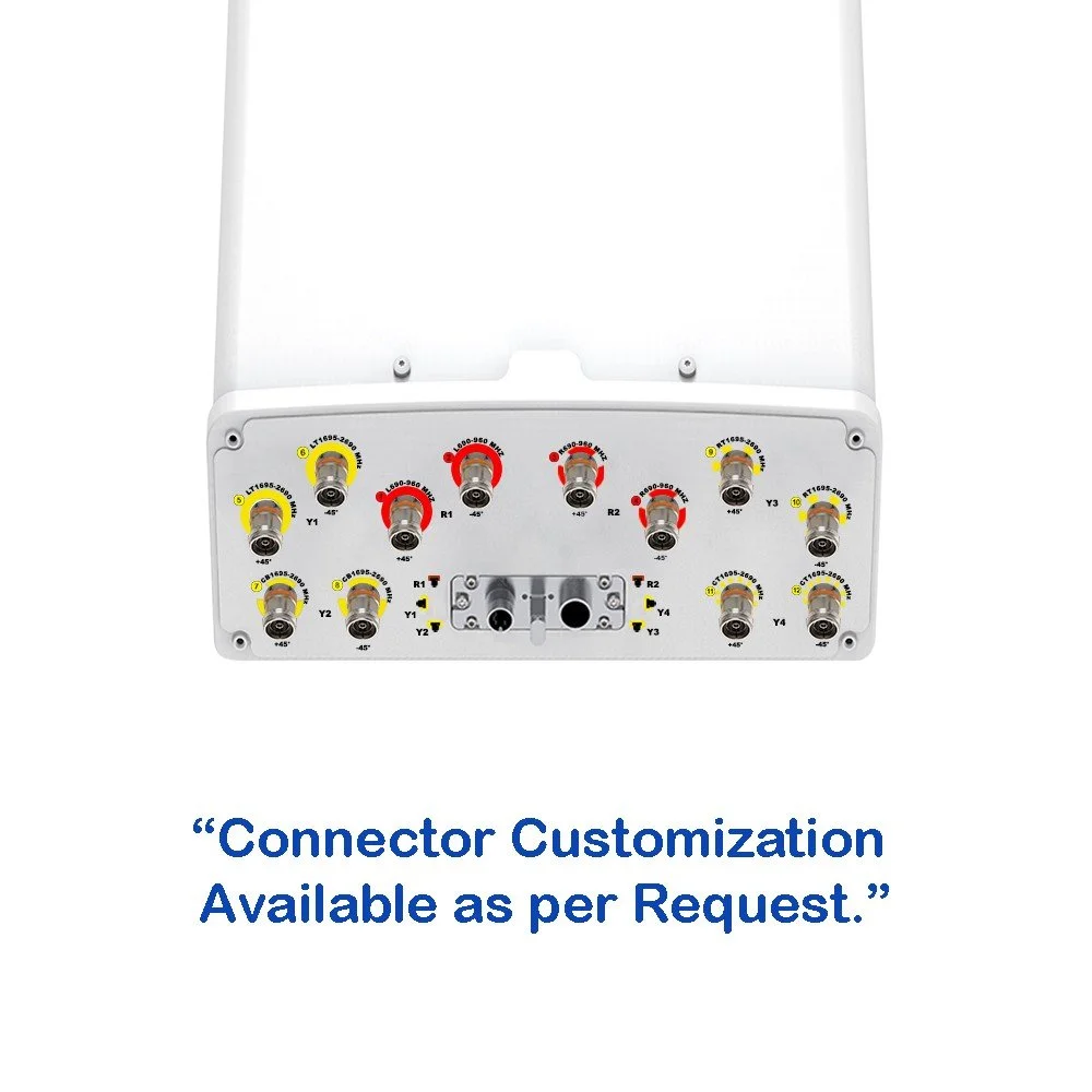
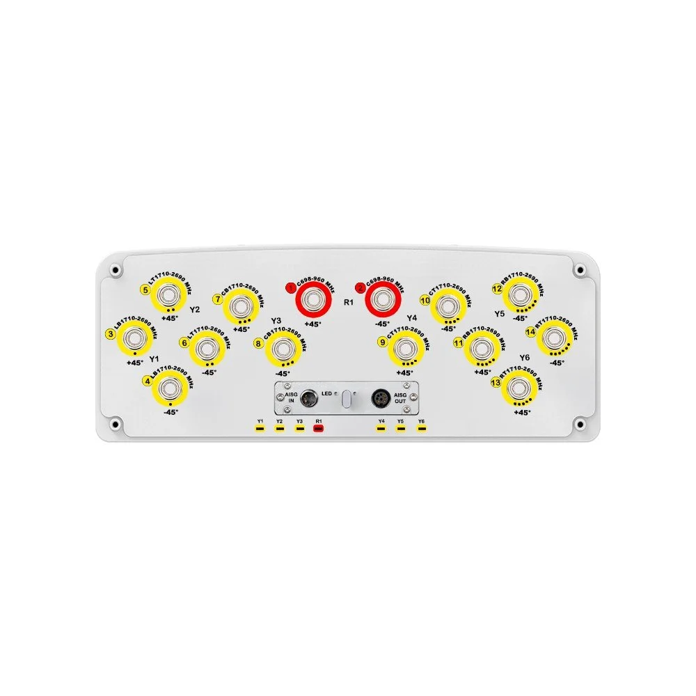
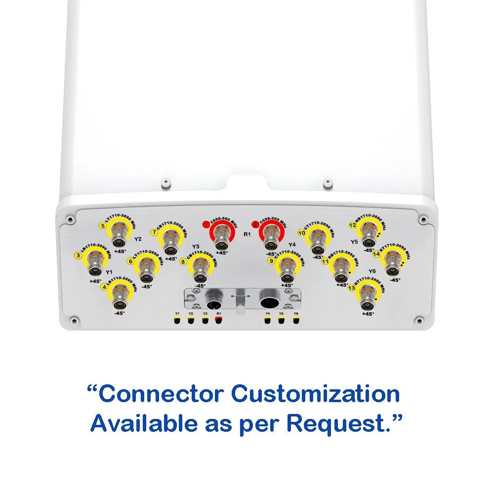
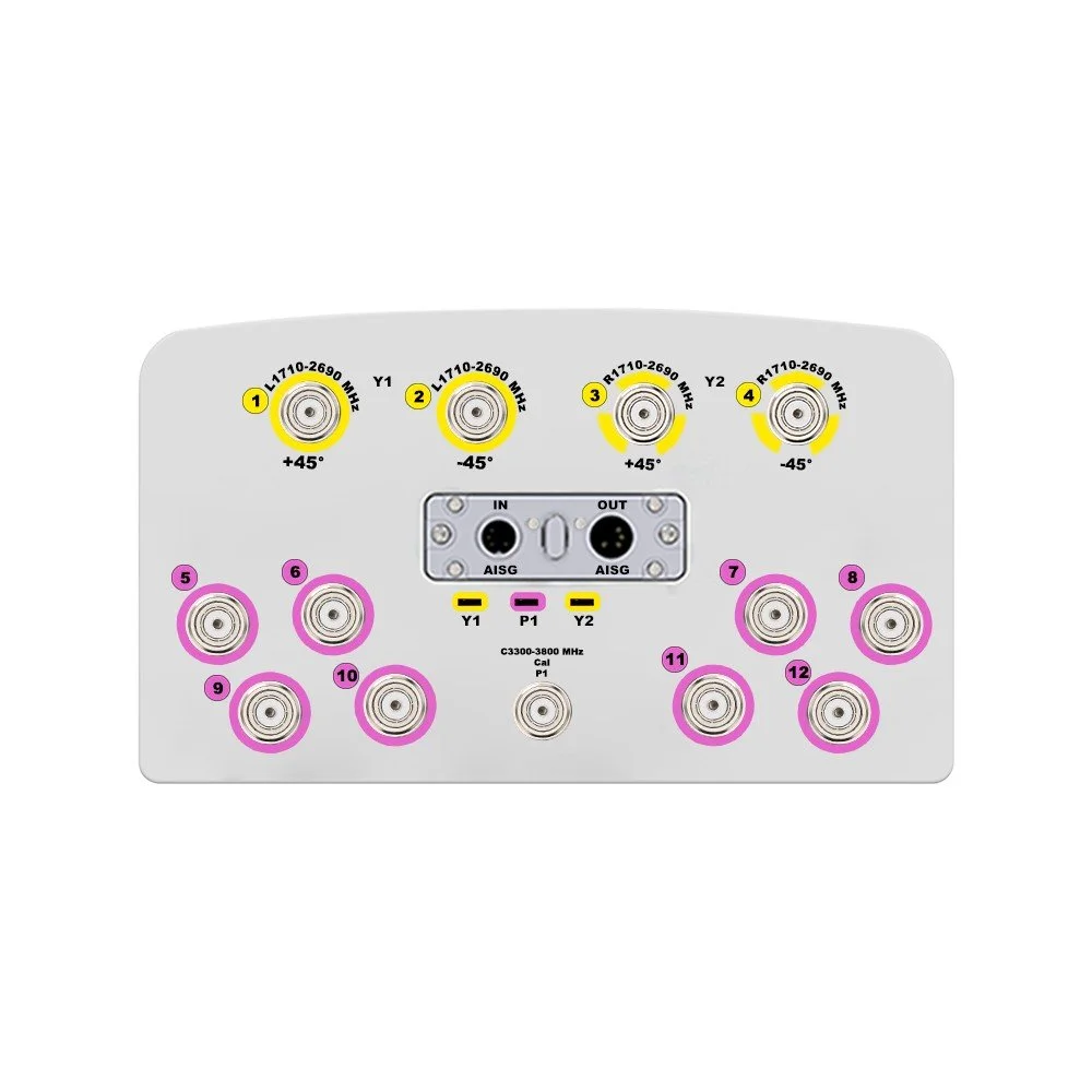
| Connector Type | — | (13x) 4.3/10 Female | |
| Connector Position | — | Bottom | |
| Electrical Tilt Control | — |
FDD: Integrated RET, Each Band Individually Controlled TDD: Integrated RET, Single Internal RET Control For All Four Antenna Arrays |
|
| Radome Material | — | UPVC | |
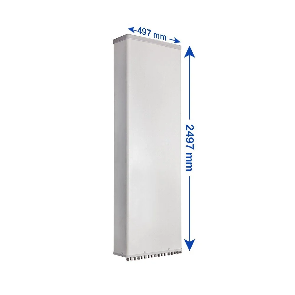
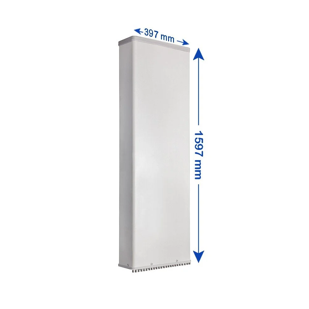
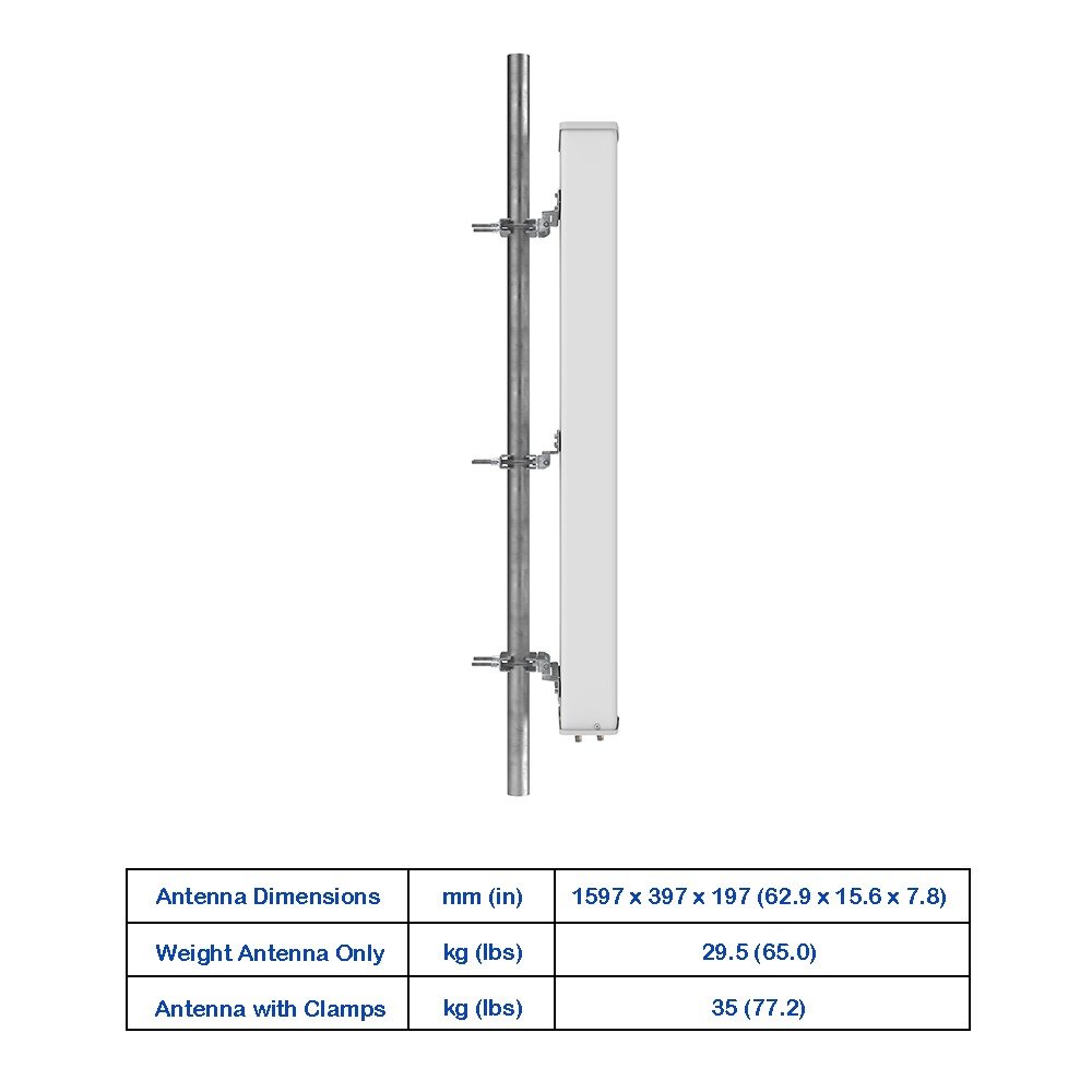
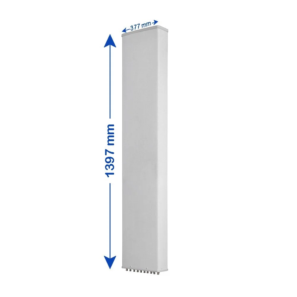
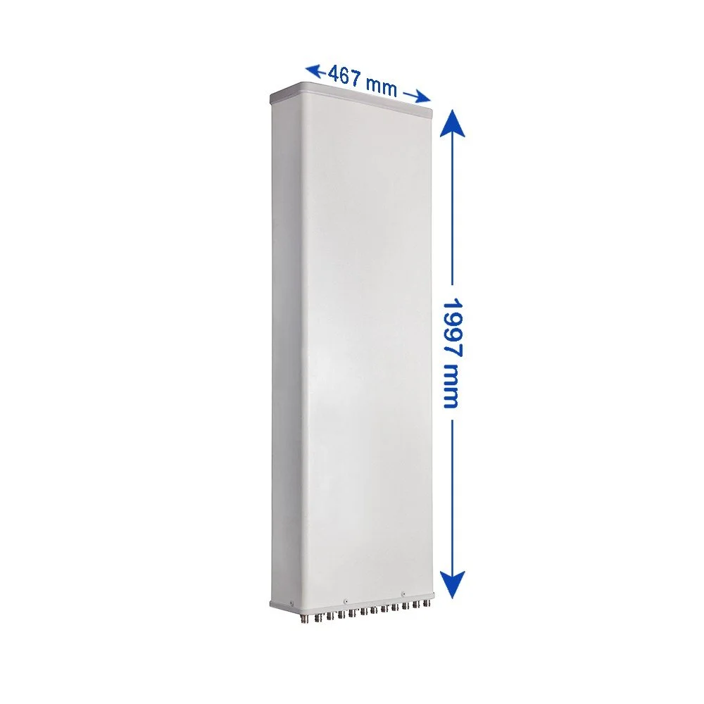
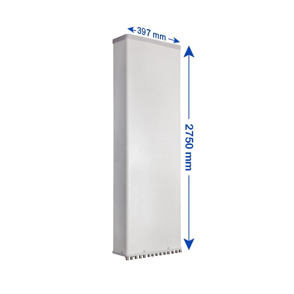
| Antenna Dimensions (H × W × D) | mm (in) | 2497 × 277 × 167 (98.3 × 10.9 × 6.6) | |
| Antenna Weight | Antenna Only | kg (lbs) | 22.5 (49.6) |
| With Clamps | kg (lbs) | 26.5 (58.4) | |
| Maximum Wind Speed | km/h (mph) | 200 (124.3) | |
| Wind Load at 150 km/h | Frontal | N (lbf) | 640 (143.9) |
| Rear | N (lbf) | 715 (160.7) | |
| Lateral | N (lbf) | 475 (106.8) | |
| Operating Temperature | °C (°F) | -40 to +60 (-40 to +140) | |