 Image 1 of 6
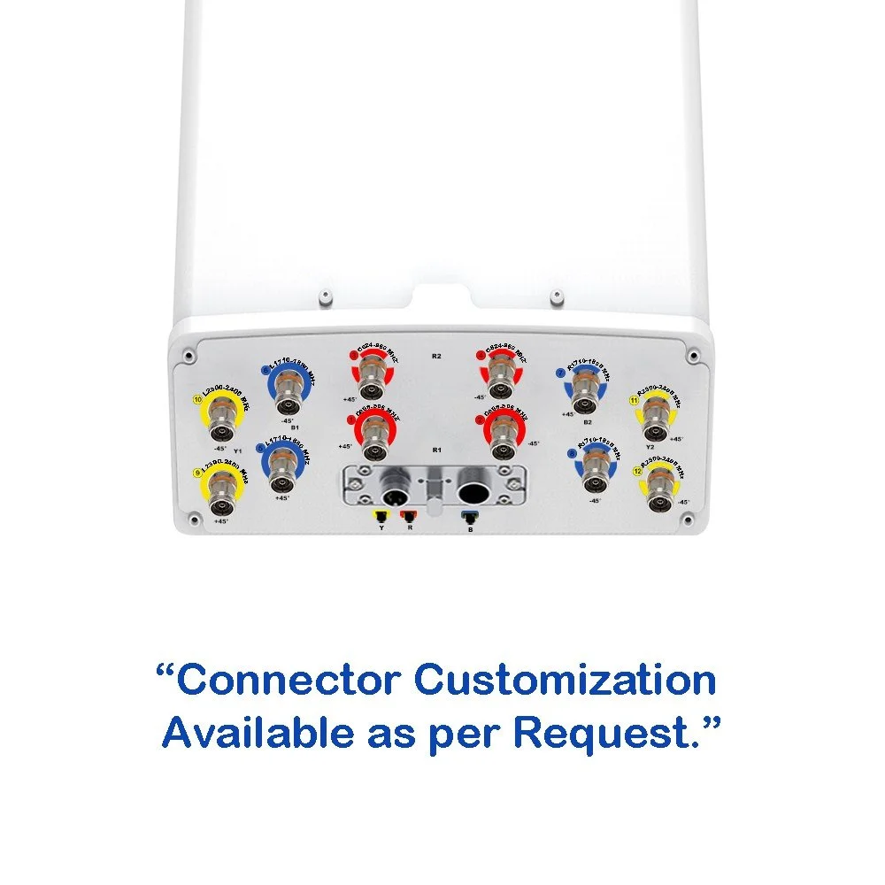 Image 2 of 6
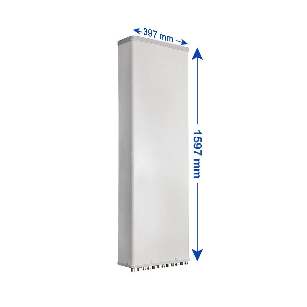 Image 3 of 6
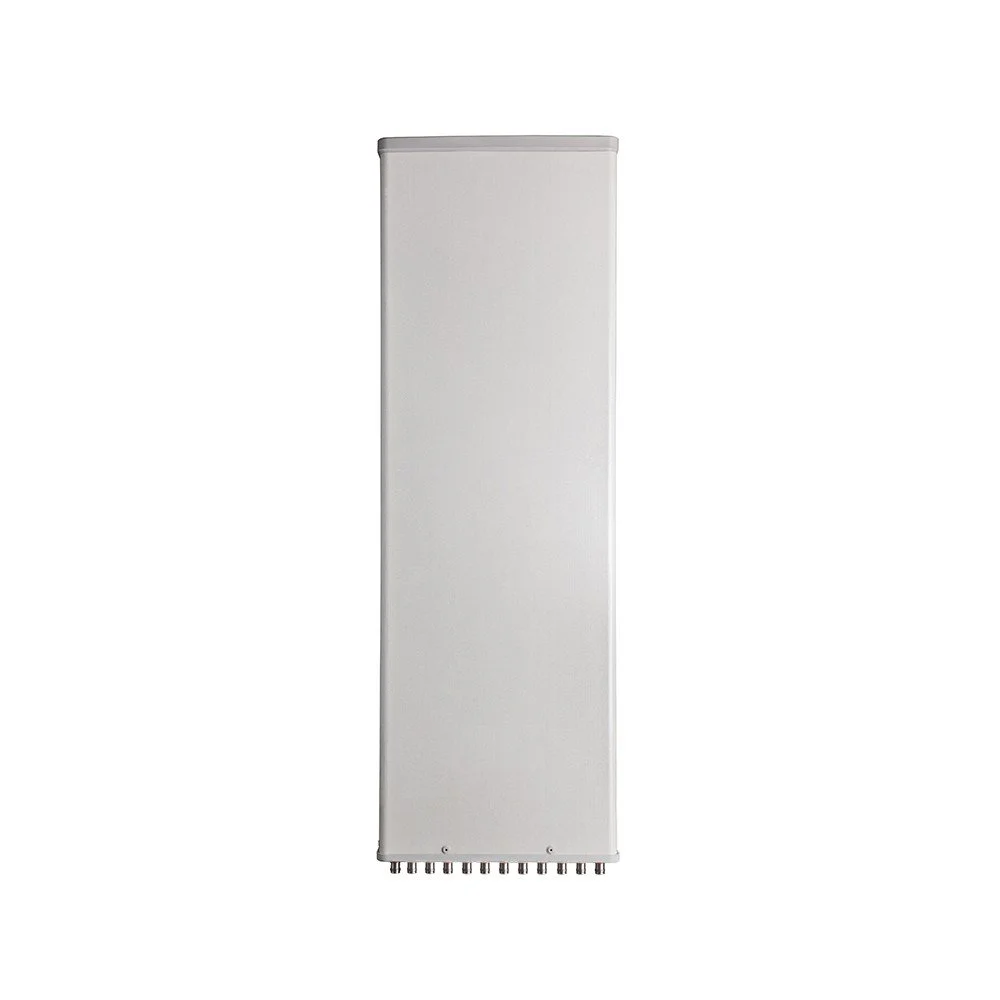 Image 4 of 6
 Image 5 of 6
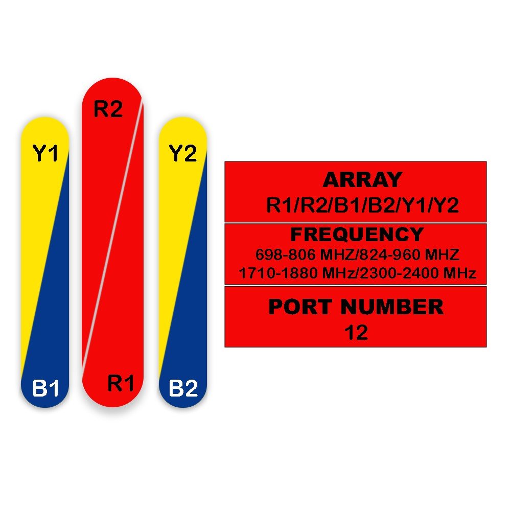 Image 6 of 6
Electrical Specifications
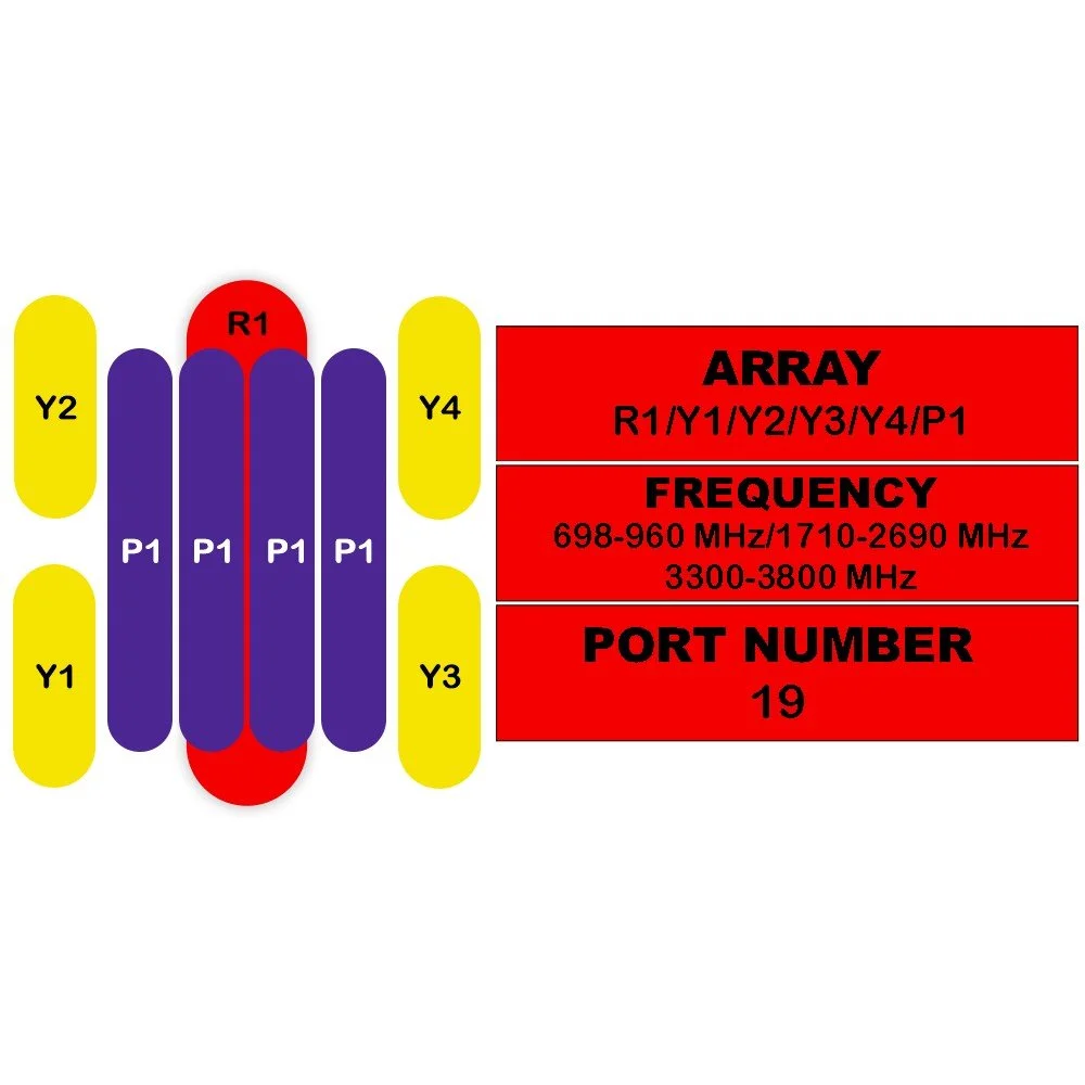
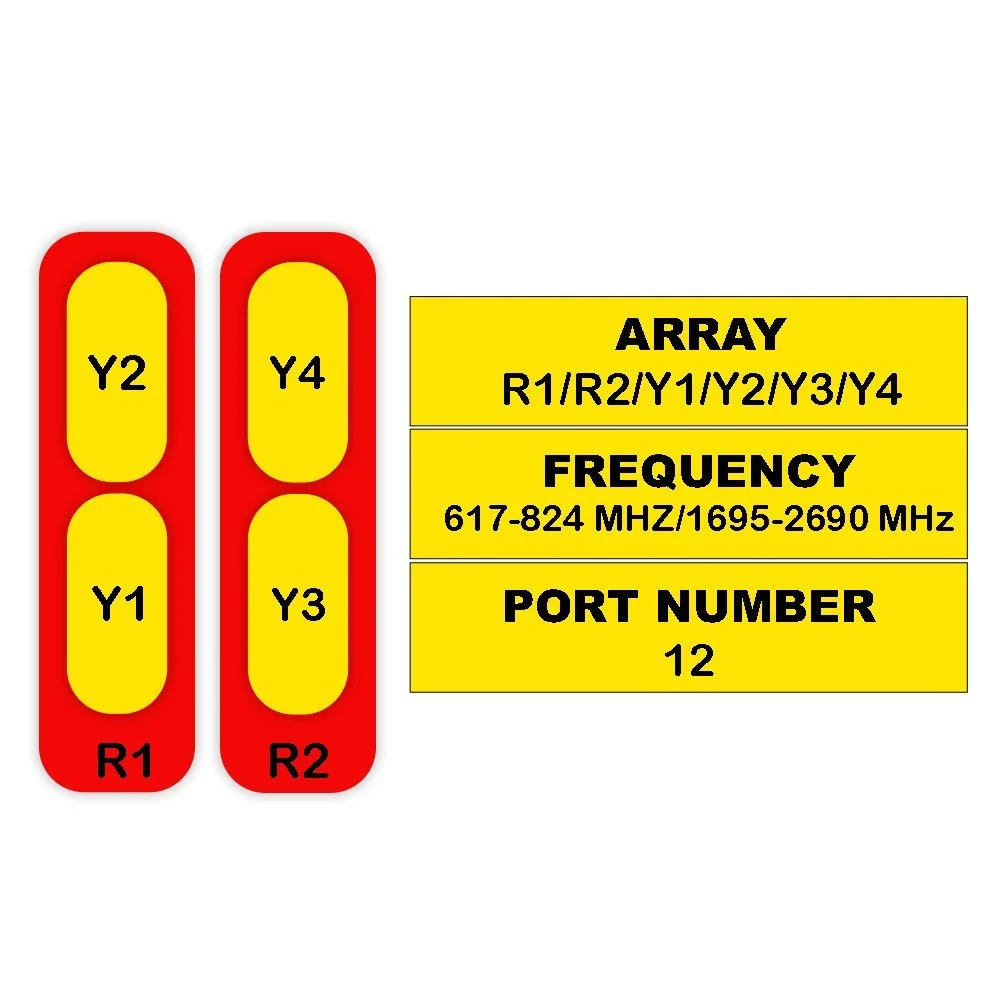
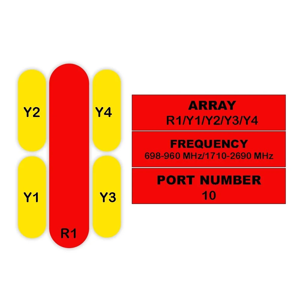
| Parameter | Unit | R1 | R2 (824–896) | R2 (880–960) | B1/B2 | Y1/Y2 |
|---|---|---|---|---|---|---|
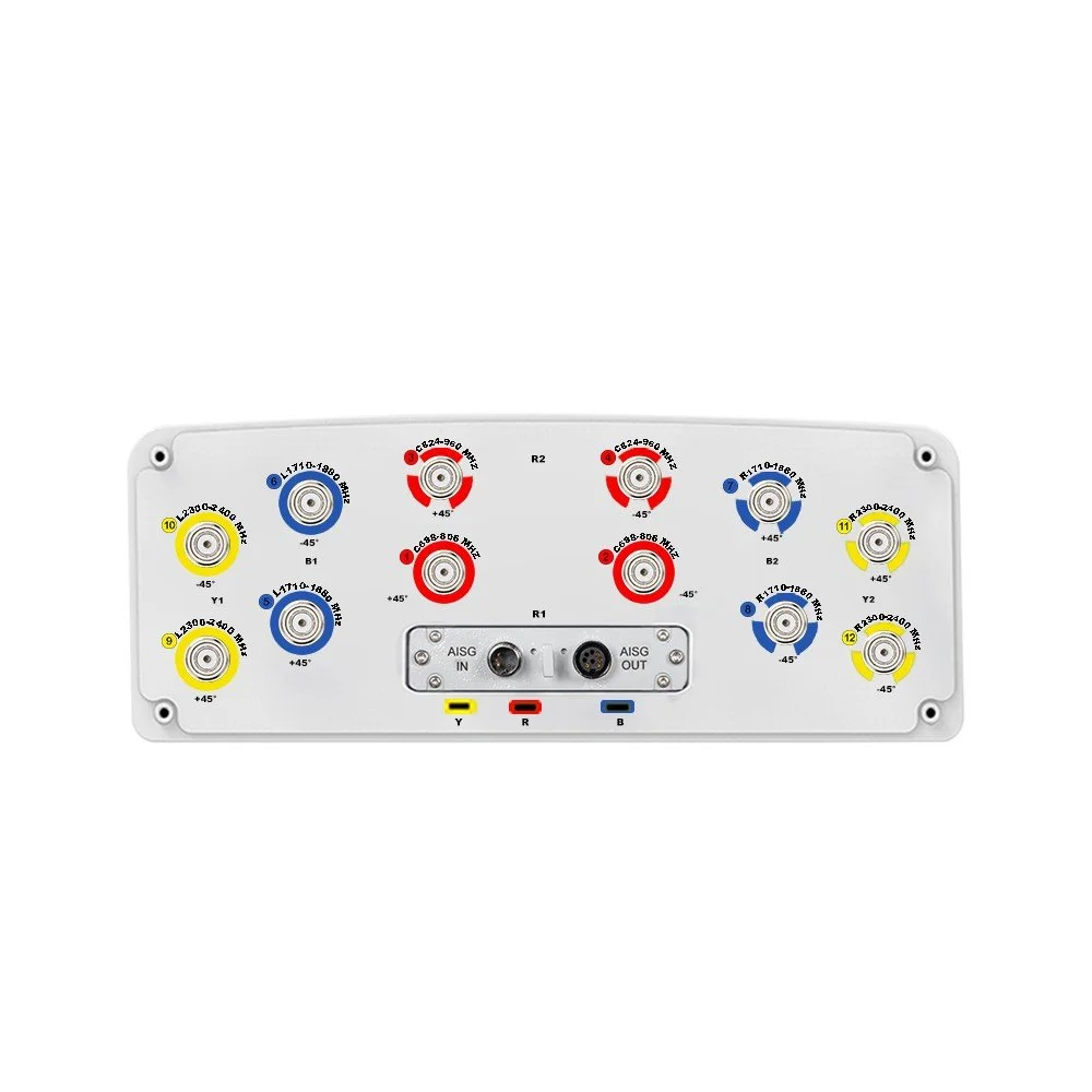
| Frequency Range | MHz | 698–806 | 824–896 | 880–960 | 1710–1880 | 1920–2170 |
| Polarization | — | ±45° | ±45° | ±45° | ±45° | ±45° |
| Gain (Mid Tilt) | dBi | 13.9 | 14.2 | 14.6 | 16.4 | 17.2 |
| Gain (All Tilts) | dBi | 13.7 ± 0.6 | 14.0 ± 0.5 | 14.4 ± 0.5 | 16.2 ± 0.6 | 17.0 ± 0.6 |
| Horizontal Beamwidth | ° | 68 ± 4.5 | 66 ± 5.5 | 64 ± 4.5 | 69 ± 5.5 | 62 ± 4.5 |
| Vertical Beamwidth | ° | 14.9 ± 1.1 | 13.2 ± 0.9 | 12.3 ± 0.9 | 6.2 ± 0.5 | 4.8 ± 0.5 |
| Electrical Downtilt (Adjustable) | ° | 4–14 | 4–14 | 4–14 | 0–10 | 0–10 |
| Tilt Accuracy | ° | < 1 | < 1 | < 1 | < 1 | < 1 |
| First Upper Side Lobe Suppression | dB | > 15 | > 15 | > 15 | > 15 | > 15 |
| Front-to-Back Ratio (±30°) | dB | > 24 | > 25 | > 25 | > 25 | > 26 |
| Cross Polar (Boresight) | dB | > 18 | > 18 | > 18 | > 18 | > 18 |
| Discrimination (Over Sector) | dB | > 7 | > 6 | > 6 | > 8 | > 8 |
| Isolation (Cross-Polar) | dB | > 25 | > 25 | > 25 | > 25 | > 25 |
| Isolation (Port-to-Port) | dB | > 30 | > 30 | > 30 | > 30 | > 30 |
| Impedance | Ohm | 50 | 50 | 50 | 50 | 50 |
| VSWR | — | < 1.5 | < 1.5 | < 1.5 | < 1.5 | < 1.5 |
| Return Loss | dB | > 14 | > 14 | > 14 | > 14 | > 14 |
| PIM3 (2×43 dBm Carrier) | dBc | < -150 | < -150 | < -150 | < -150 | < -150 |
| Lightning Protection | — | DC Ground | DC Ground | DC Ground | DC Ground | DC Ground |
| Max Avg Input Power per Port (50°C) | Watts | 250 | 250 | 250 | 200 | 200 |
Mechanical Specifications
| Parameter | Condition | Unit | Specification |
|---|---|---|---|
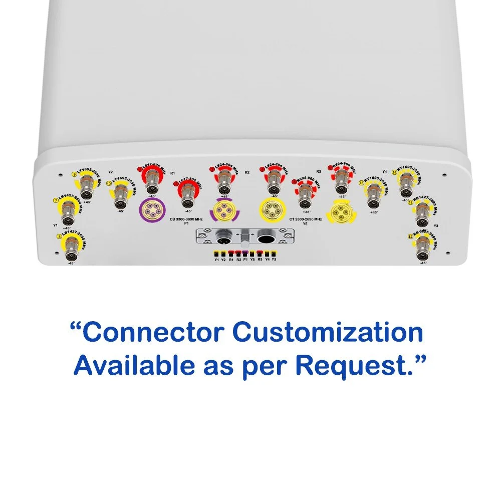
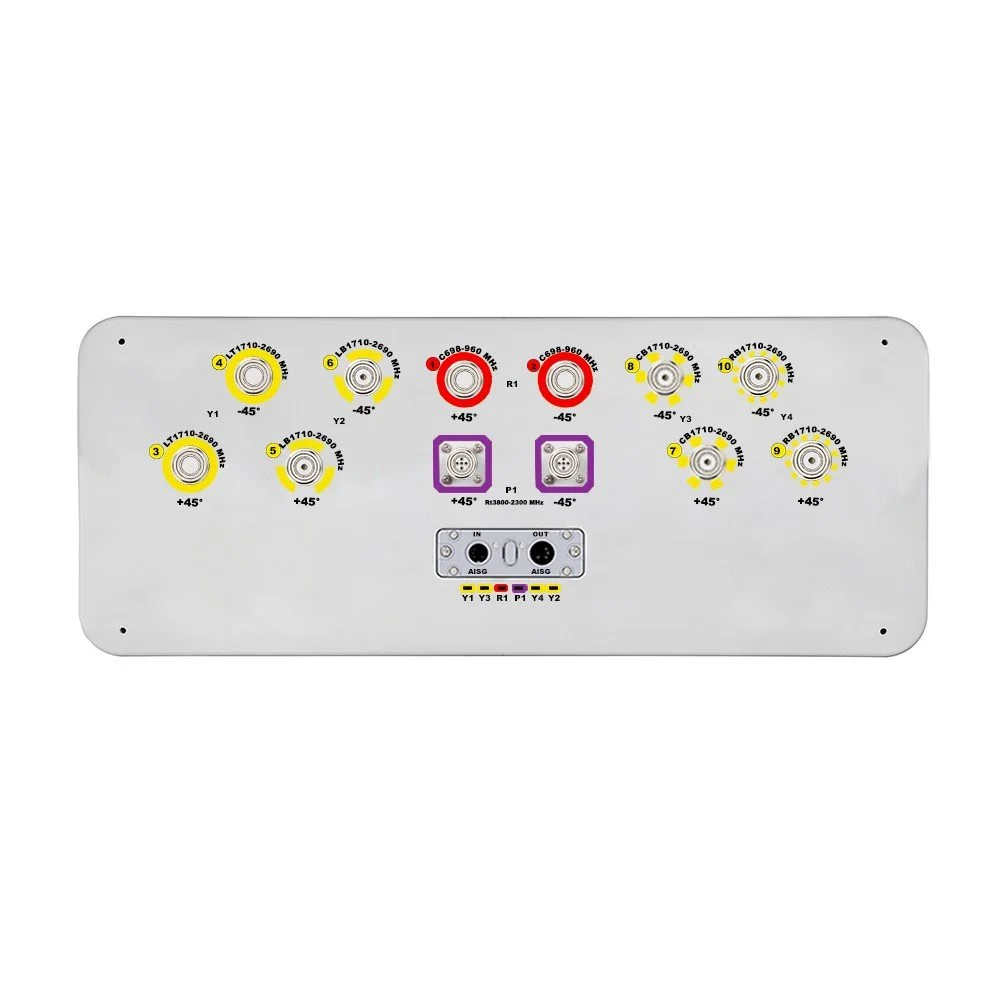
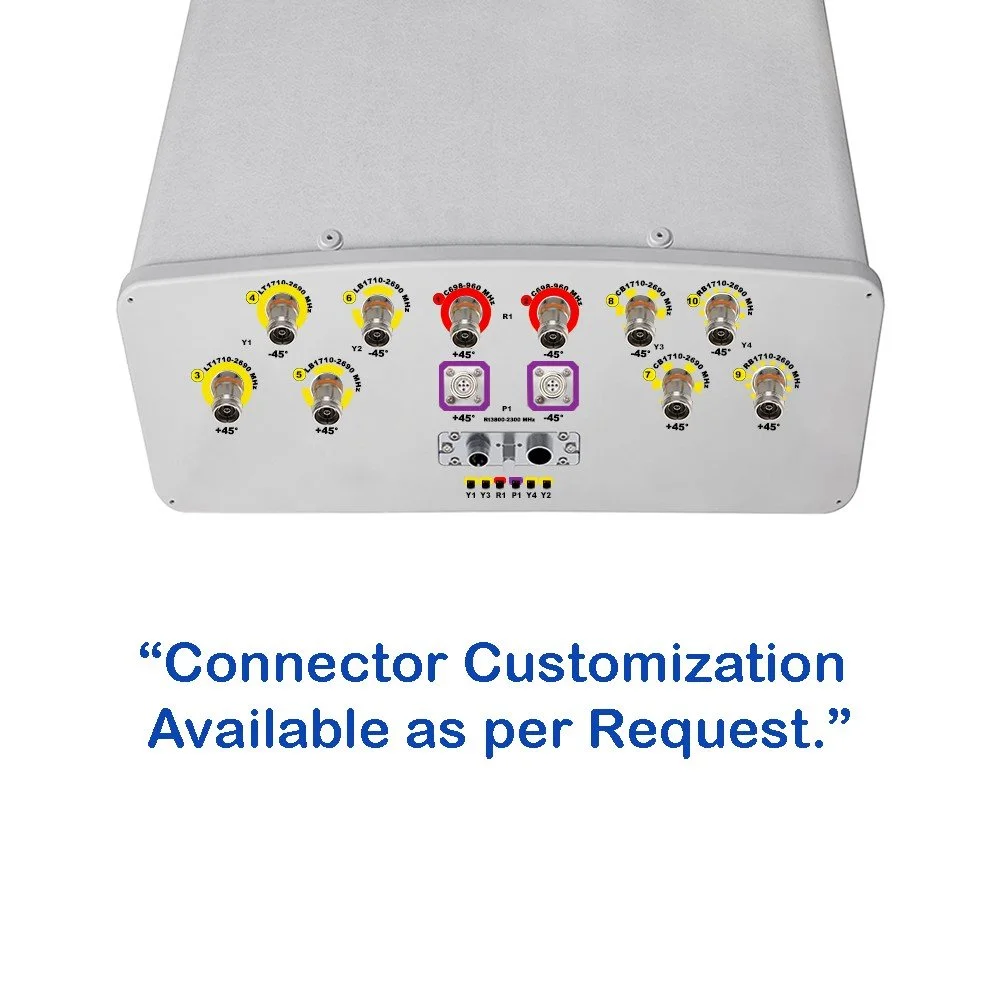
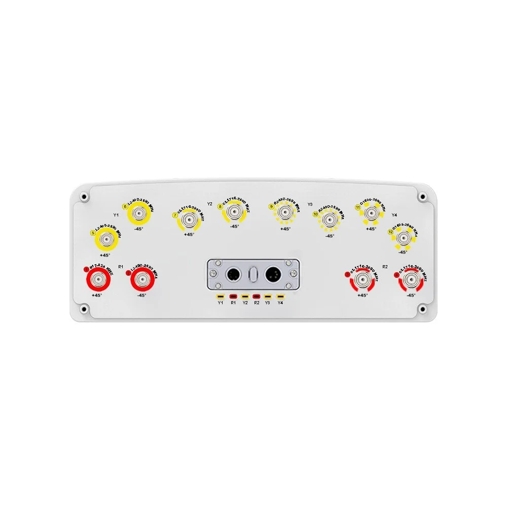
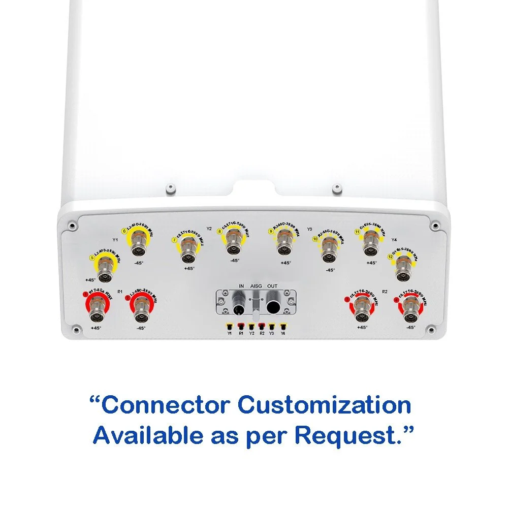
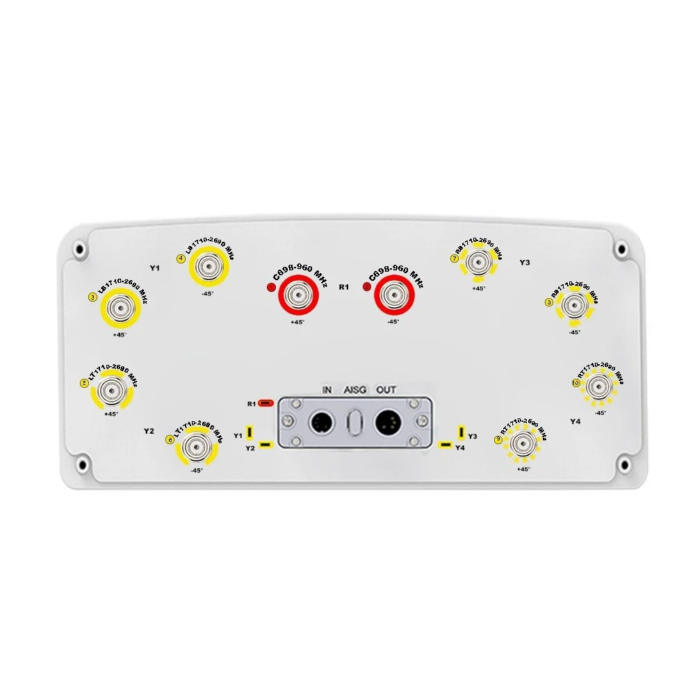
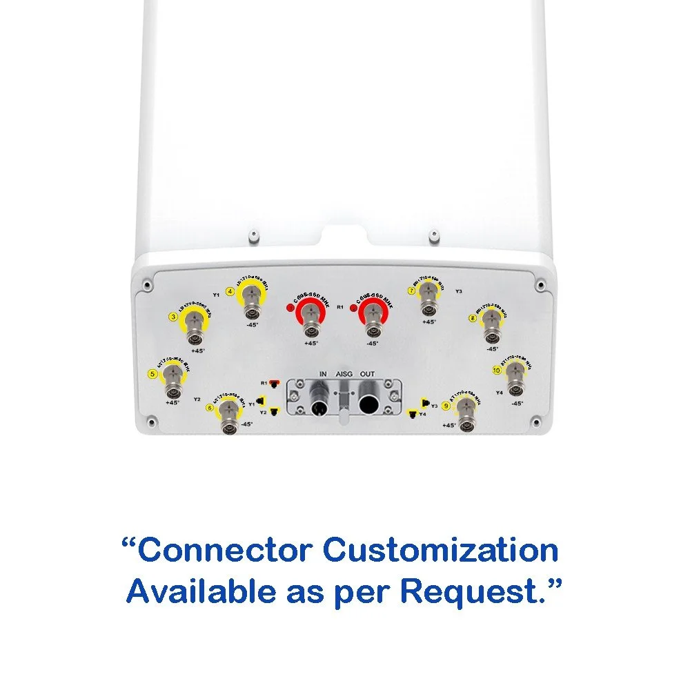
| Connector Type | — | — | (12x) 4.3/10 Female |
| Connector Position | — | — | Bottom |
| Electrical Tilt Control | — | — | Integrated RET |
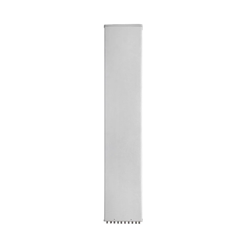
| Radome Material | — | — | Fiberglass |
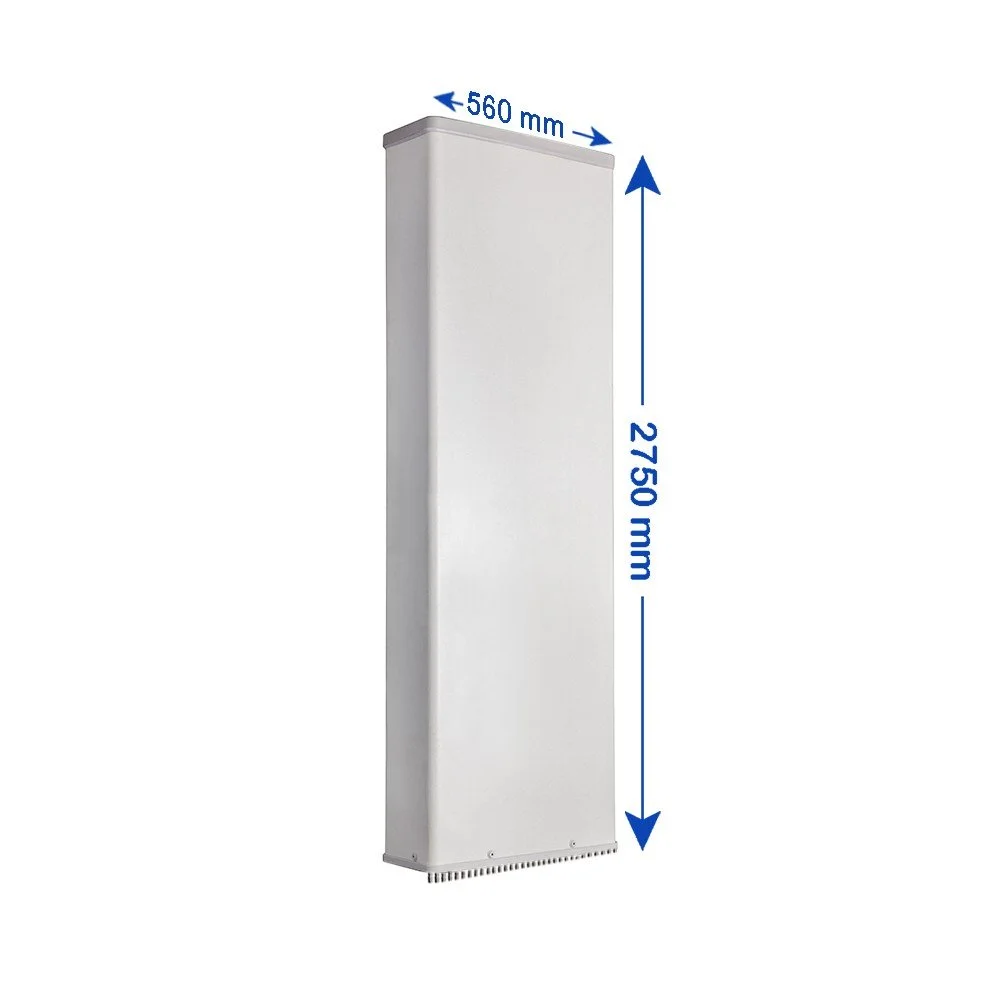
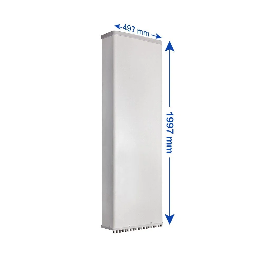
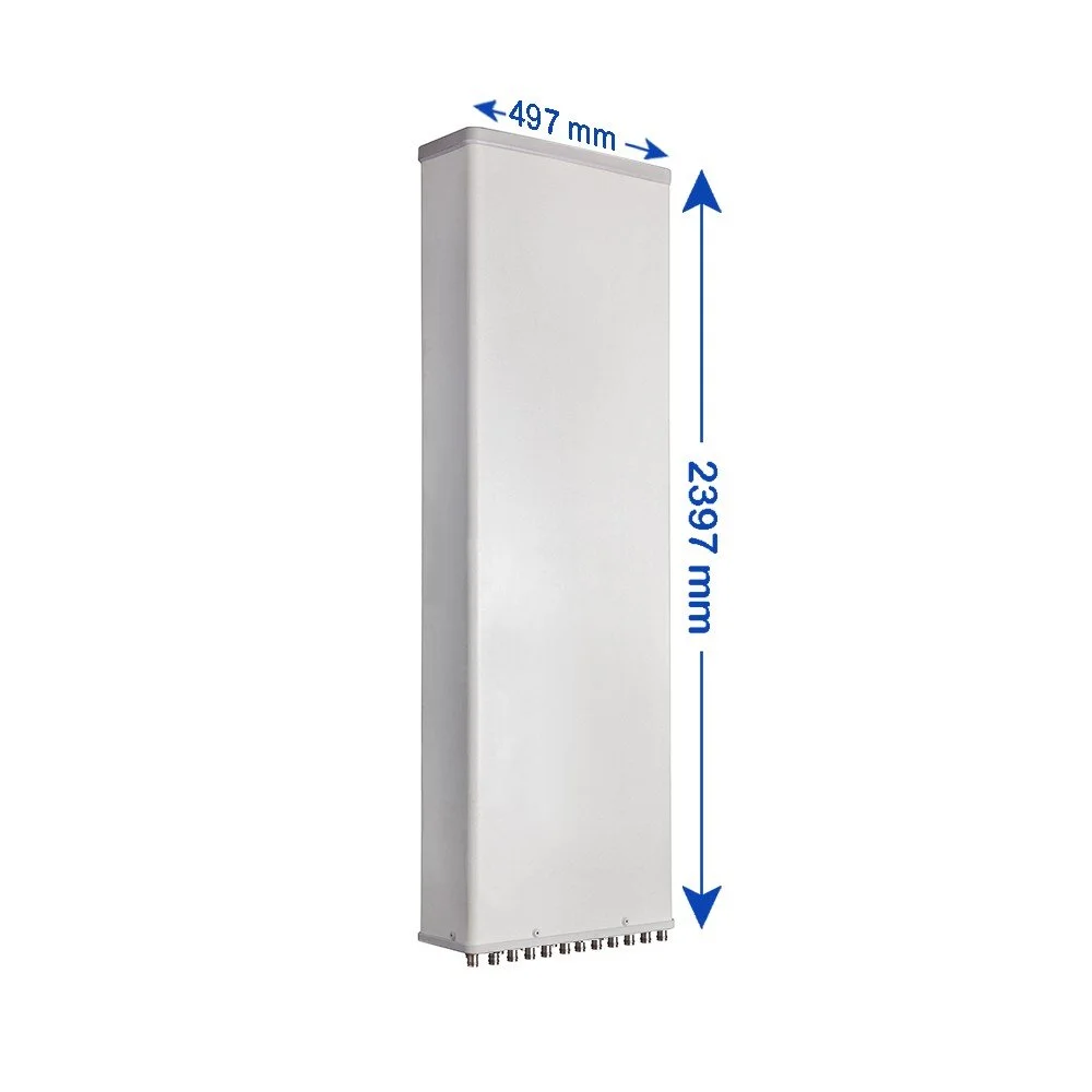
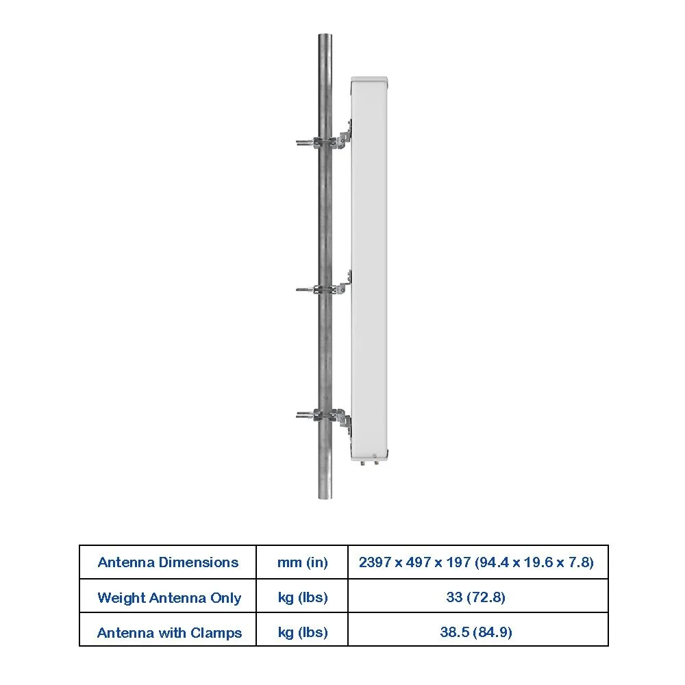
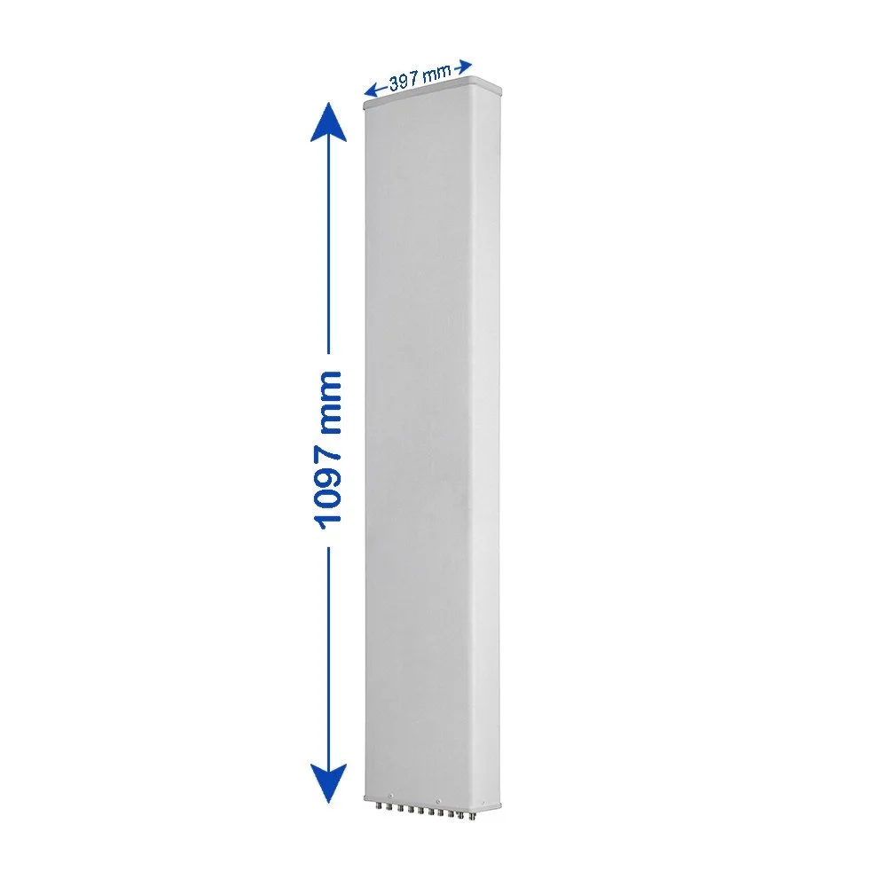
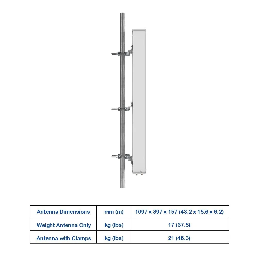
| Antenna Dimensions (H × W × D) | — | mm (in) | 1597 × 397 × 157 (62.9 × 15.6 × 6.2) |
| Antenna Weight | Antenna Only | kg (lbs) | 27 (59.5) |
| Antenna Weight | With Clamps | kg (lbs) | 31 (68.3) |
| Maximum Wind Speed | — | km/h (mph) | 200 (124.3) |
| Wind Load (at 150 km/h) | Frontal | N (lbf) | 585 (131.5) |
| Wind Load (at 150 km/h) | Rear | N (lbf) | 655 (147.2) |
| Wind Load (at 150 km/h) | Lateral | N (lbf) | 310 (69.7) |
| Operating Temperature | — | °C (°F) | -40 to +60 (-40 to +140) |