A compact, high‑performance 12‑port panel sector antenna engineered for multi‑operator and multi‑band deployments across 690–2690 MHz. Designed for dense urban macro and small cell applications, this antenna delivers consistent sector coverage, low interport coupling, and flexible mounting options to accelerate rollouts and maximize spectrum efficiency.
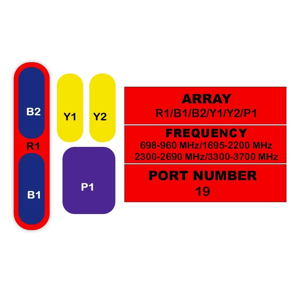
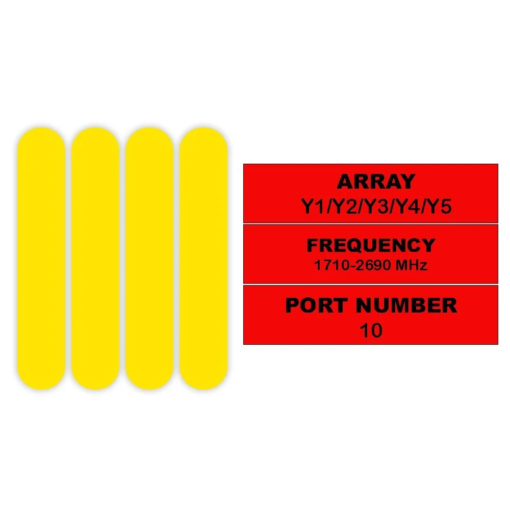
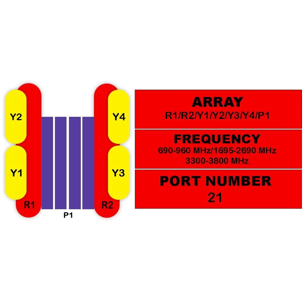
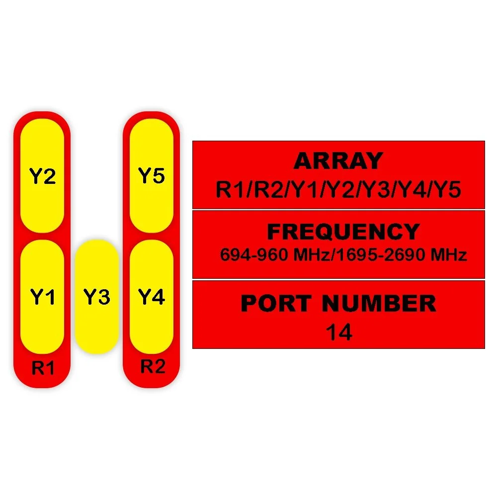
Frequency range: 690–2690 MHz (covering low‑band, mid‑band LTE/NR allocations)
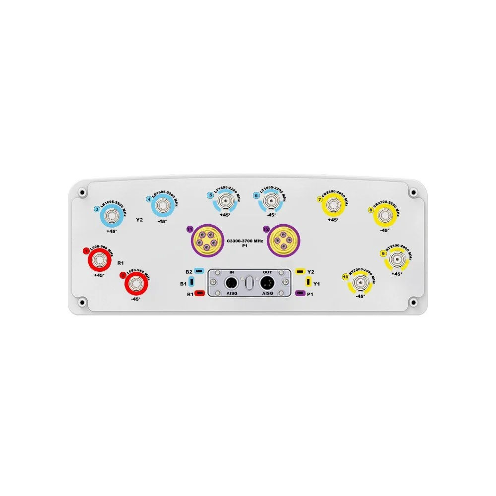
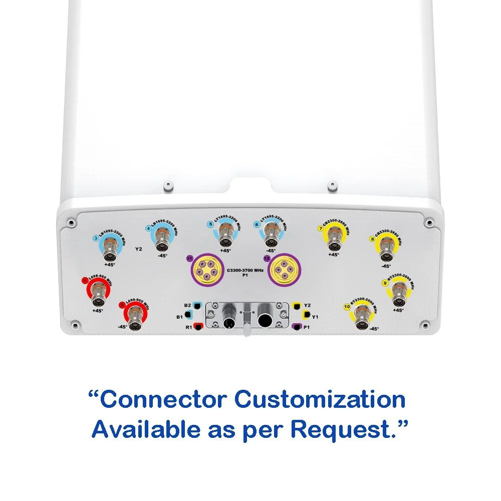
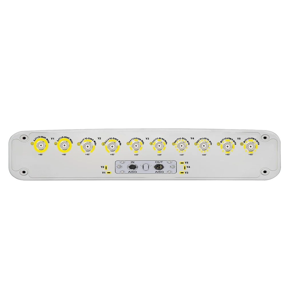
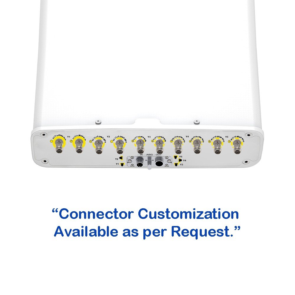
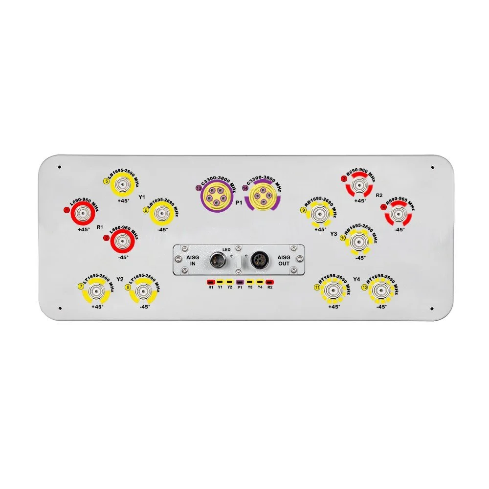
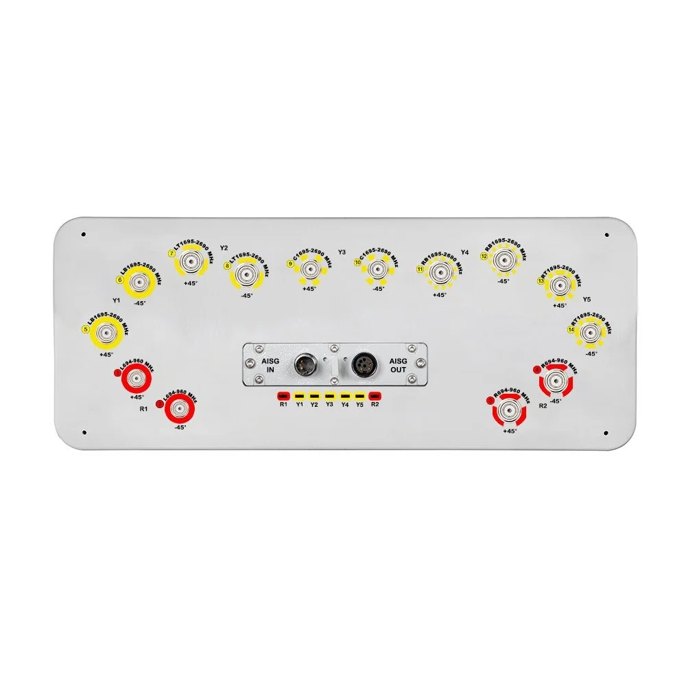
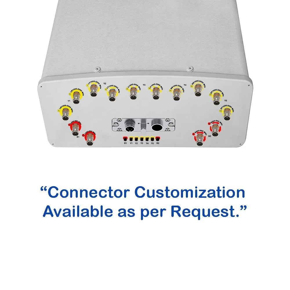
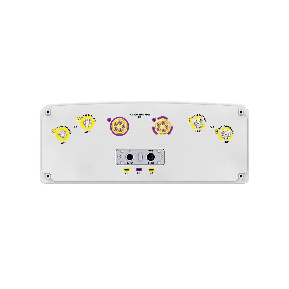
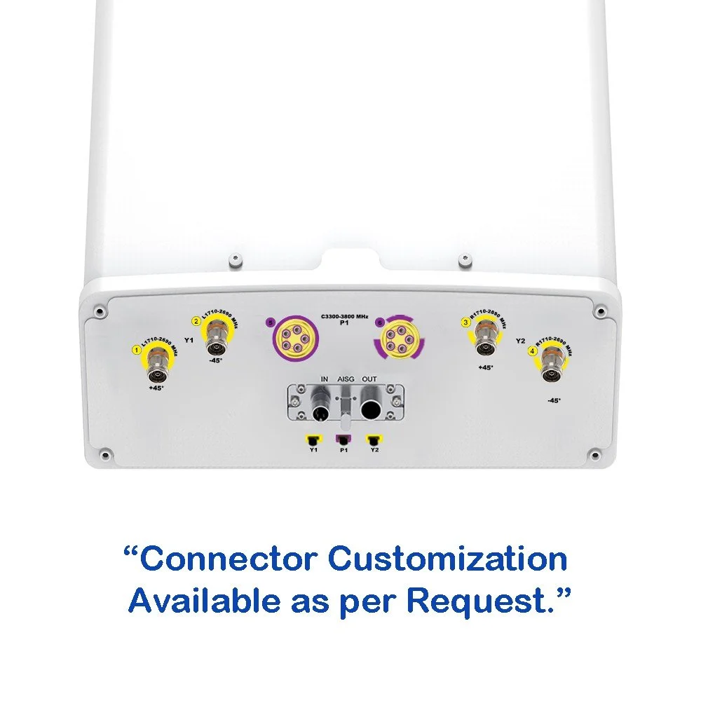
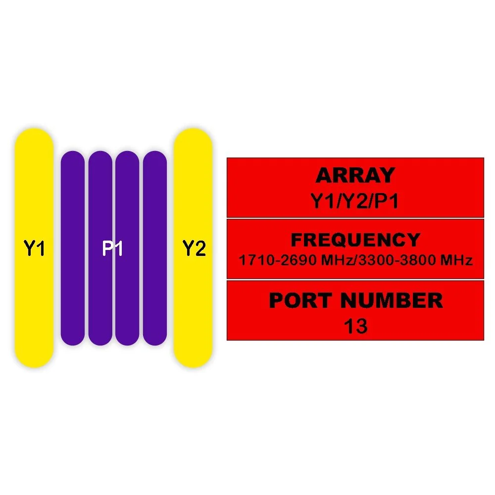
Ports: 12 independent RF ports (configurable polarization and sectorization)
Gain: Broad frequency gain optimized per band (typical: low‑band 2–6 dBi; mid‑band 6–12 dBi) — specific values per band available on request
Beamwidth: Sector azimuth ~65°–120° dependent on port configuration; elevation optimized for typical tower and rooftop heights
Isolation: High interport isolation (>25 dB typical) to support multi‑operator co‑existence and MIMO schemes
VSWR: ≤1.8:1 typical across bands
Maximum input power: 100 W per port
Impedance: 50 Ω
Polarization: Dual linear polarization per port (±45° options available); supports cross‑polarization diversity and MIMO
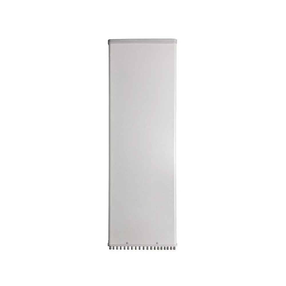
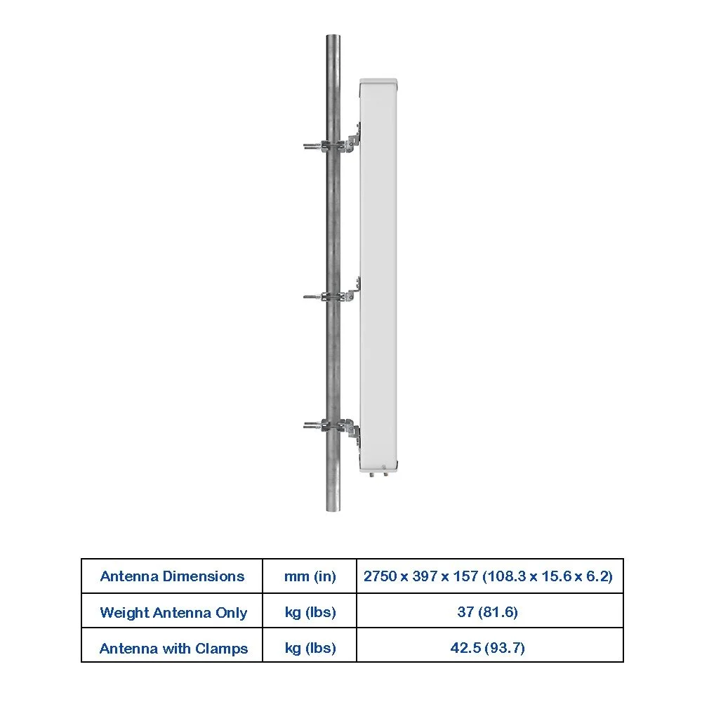
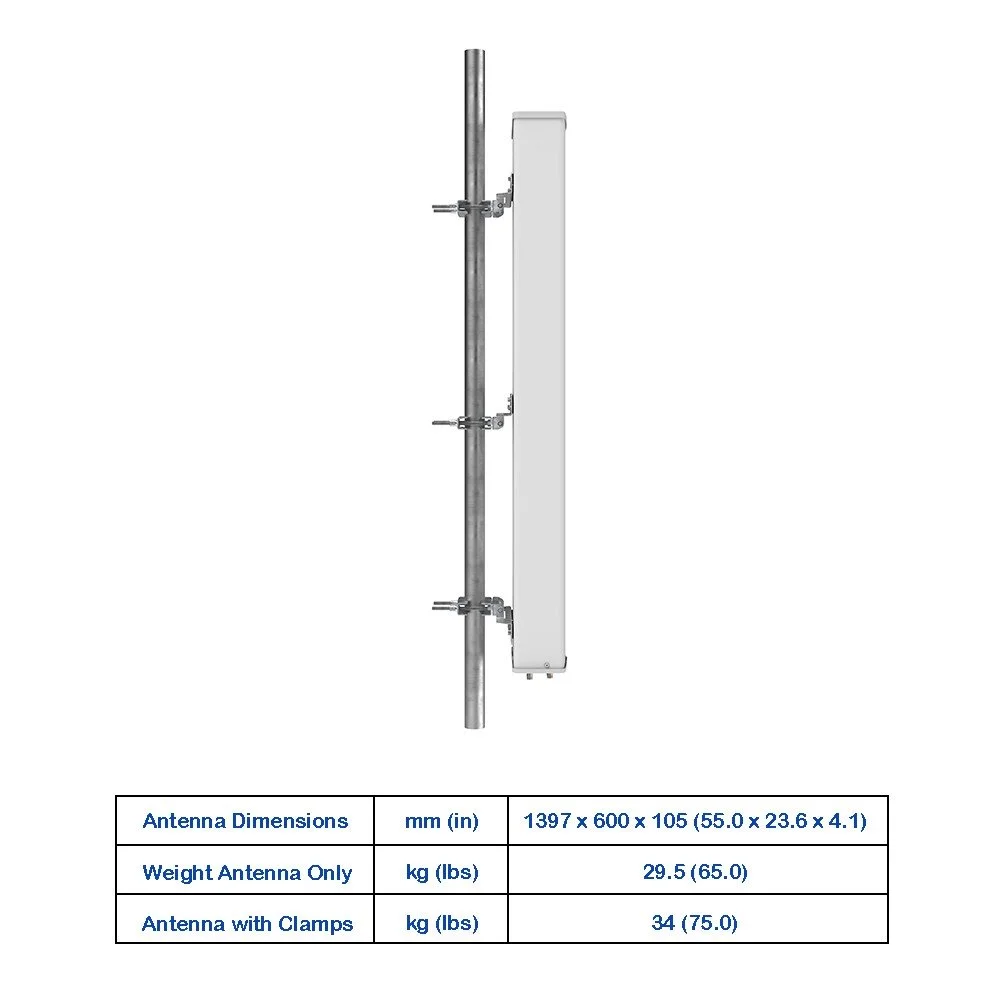
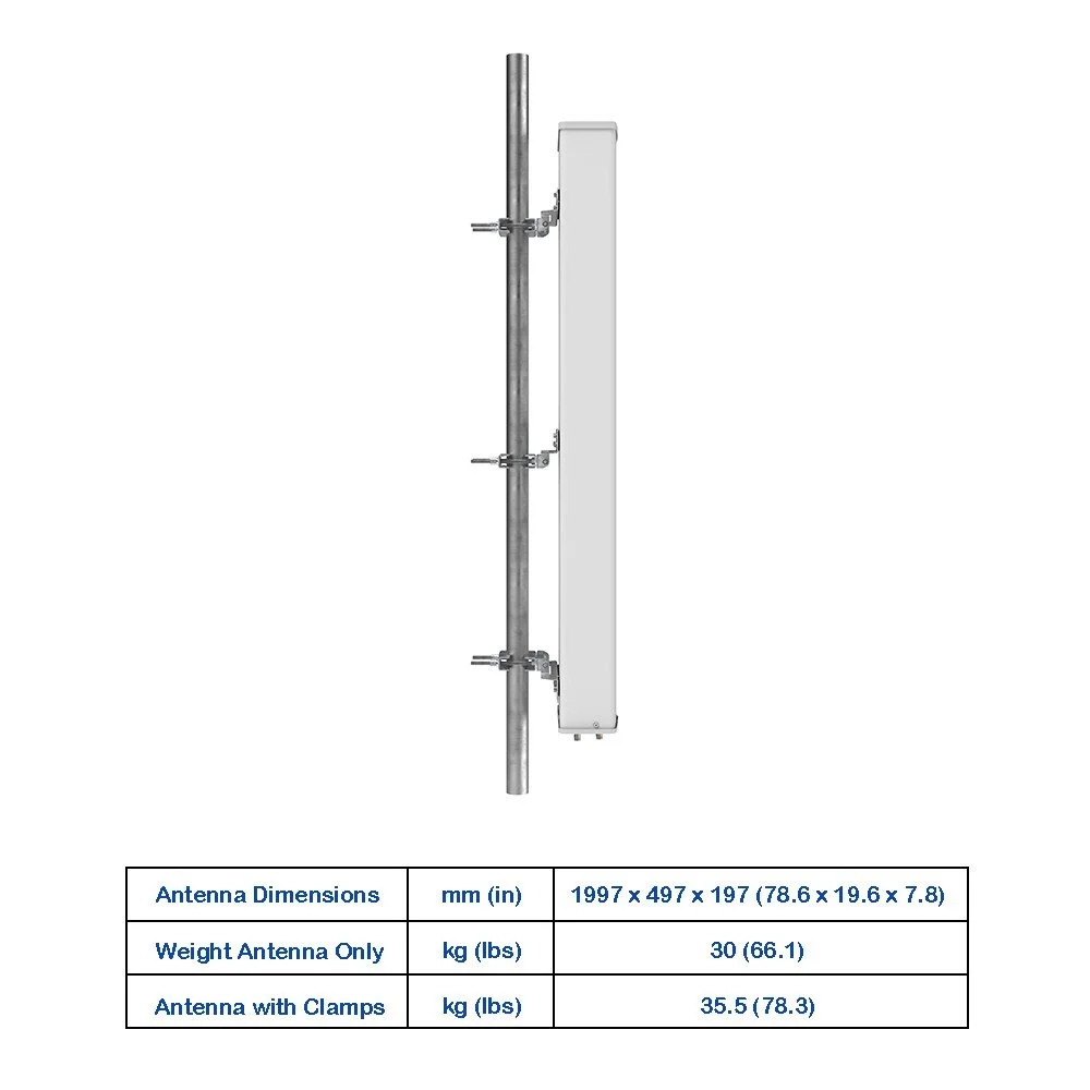
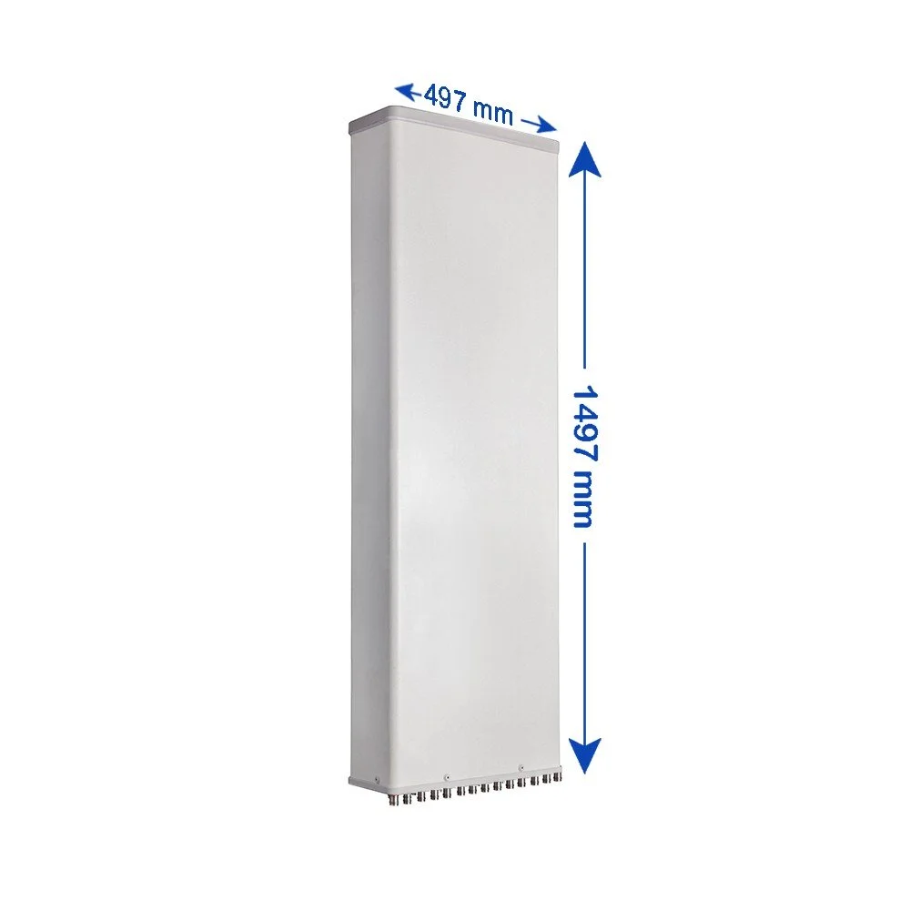
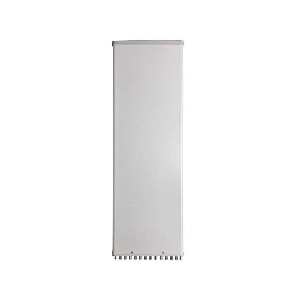
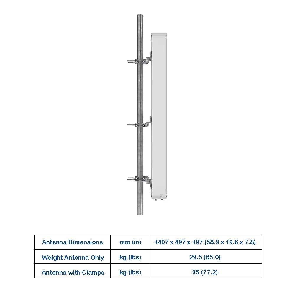
Mechanical: Robust radome, corrosion‑resistant mounting bracket, -40°C to +60°C operating temperature
Ingress protection: IP65 or better
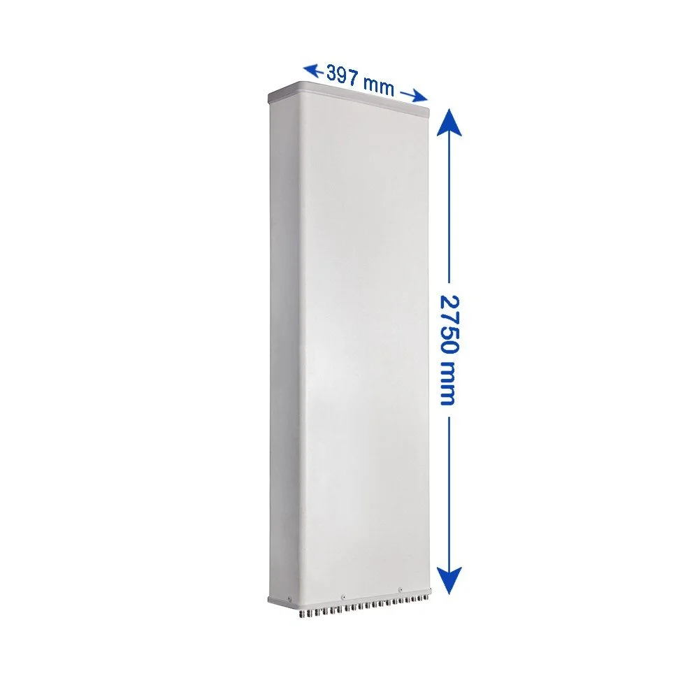
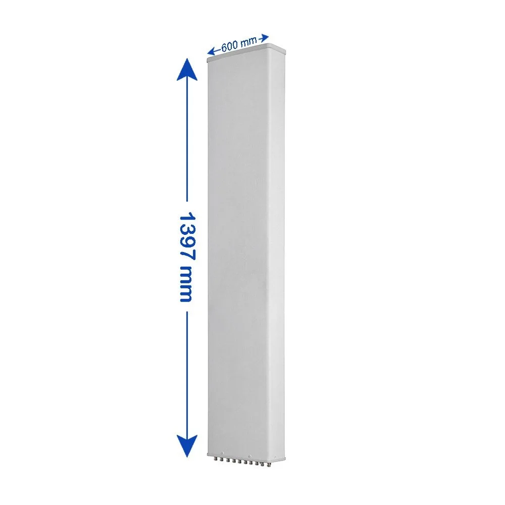
Dimensions & weight: Compact sector form factor; lightweight for pole, mast, or wall mounting (contact for exact measurements)
Compliance: RoHS; regulatory and carrier specific certifications available on request

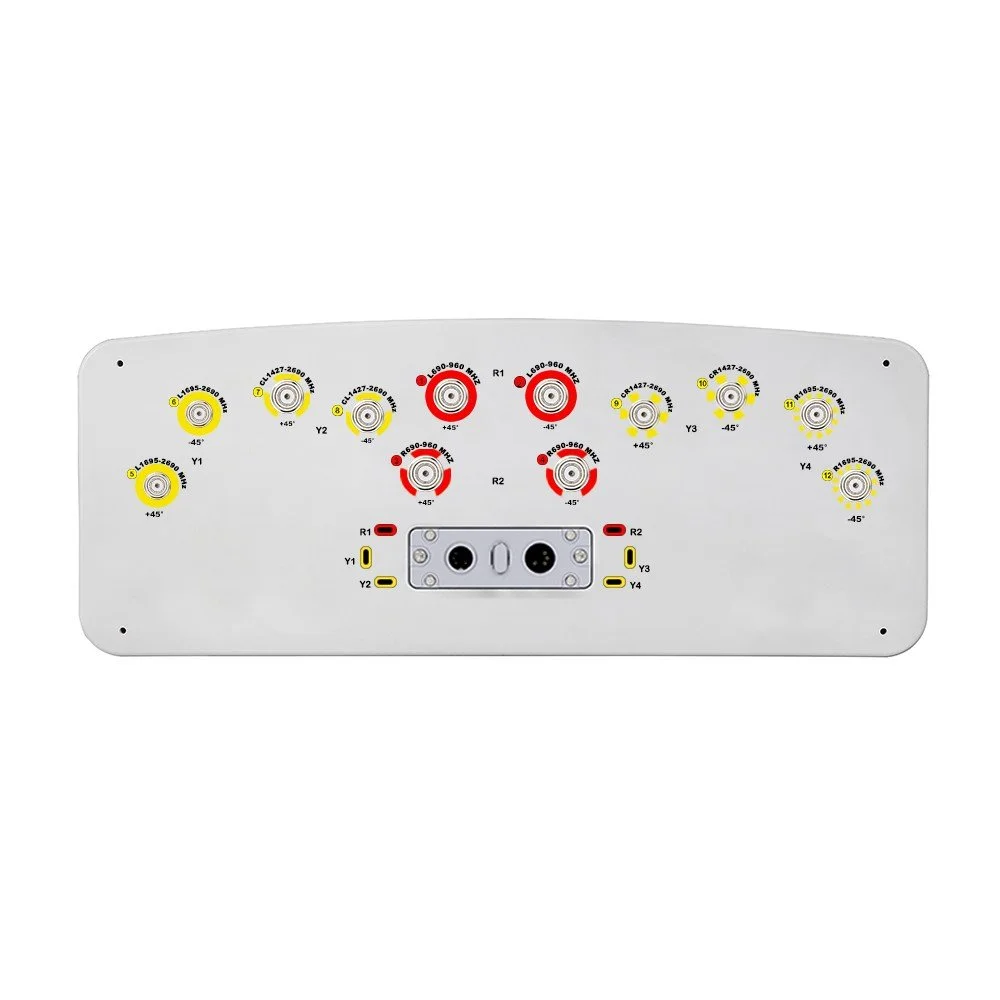 Image 1 of 6
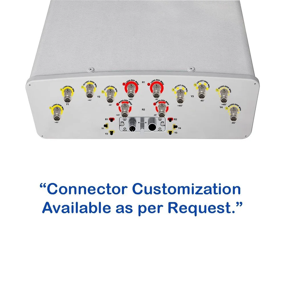 Image 2 of 6
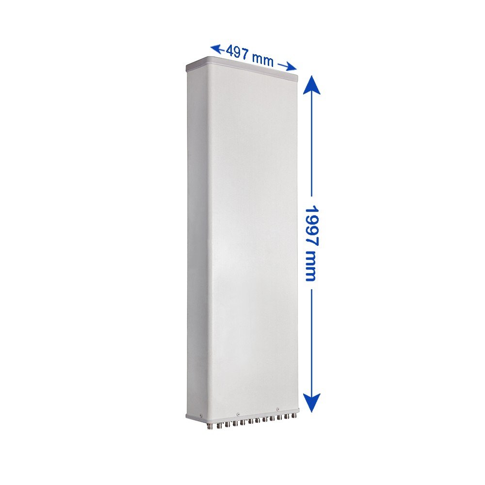 Image 3 of 6
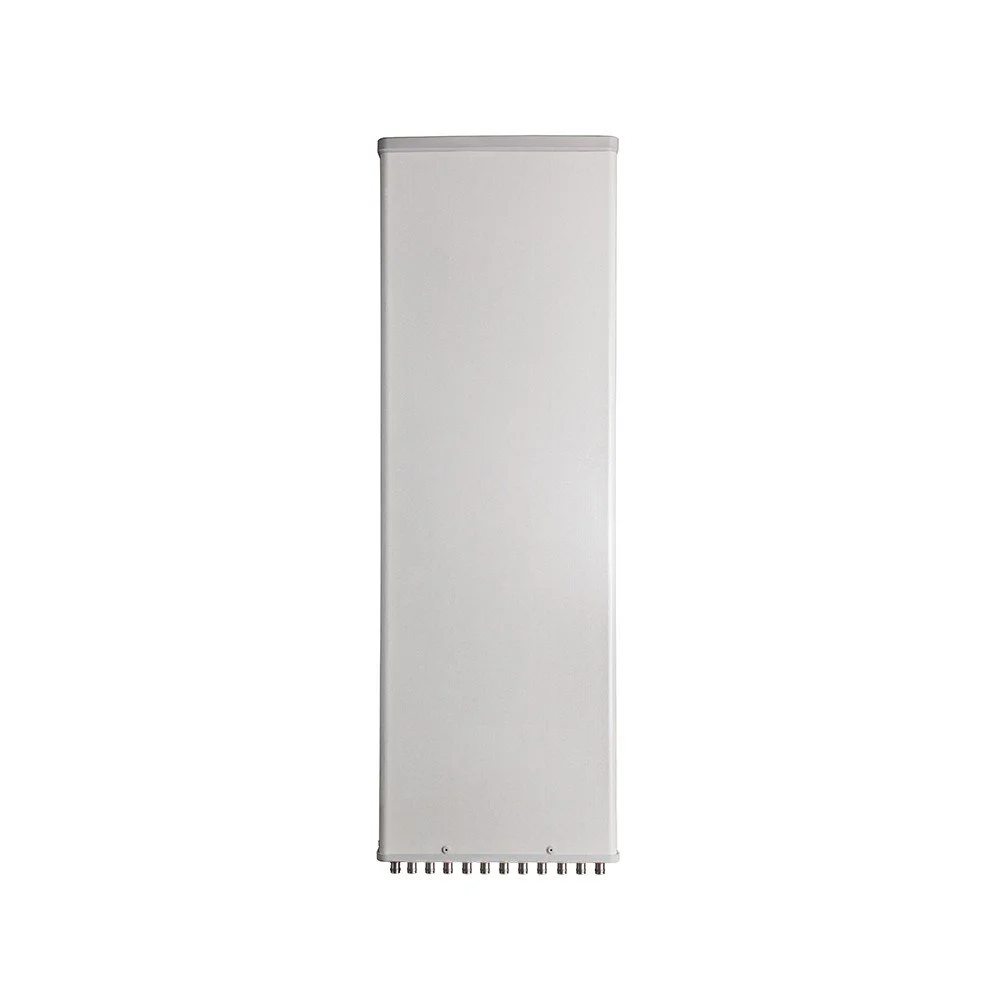 Image 4 of 6
 Image 5 of 6
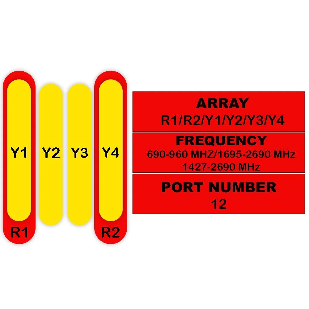 Image 6 of 6