12-Port Panel Sector Antenna (690–2690 MHz)
Overview A high-performance 12‑port panel sector antenna engineered for multi-band cellular and private wireless deployments spanning 690–2690 MHz. Optimized for high-capacity urban and suburban sectors, this antenna delivers consistent sector coverage, low inter-port coupling, and flexible mounting for rapid deployment in 4G and 5G Non-Standalone (NSA) overlay scenarios and modern LTE networks.
Key Features :
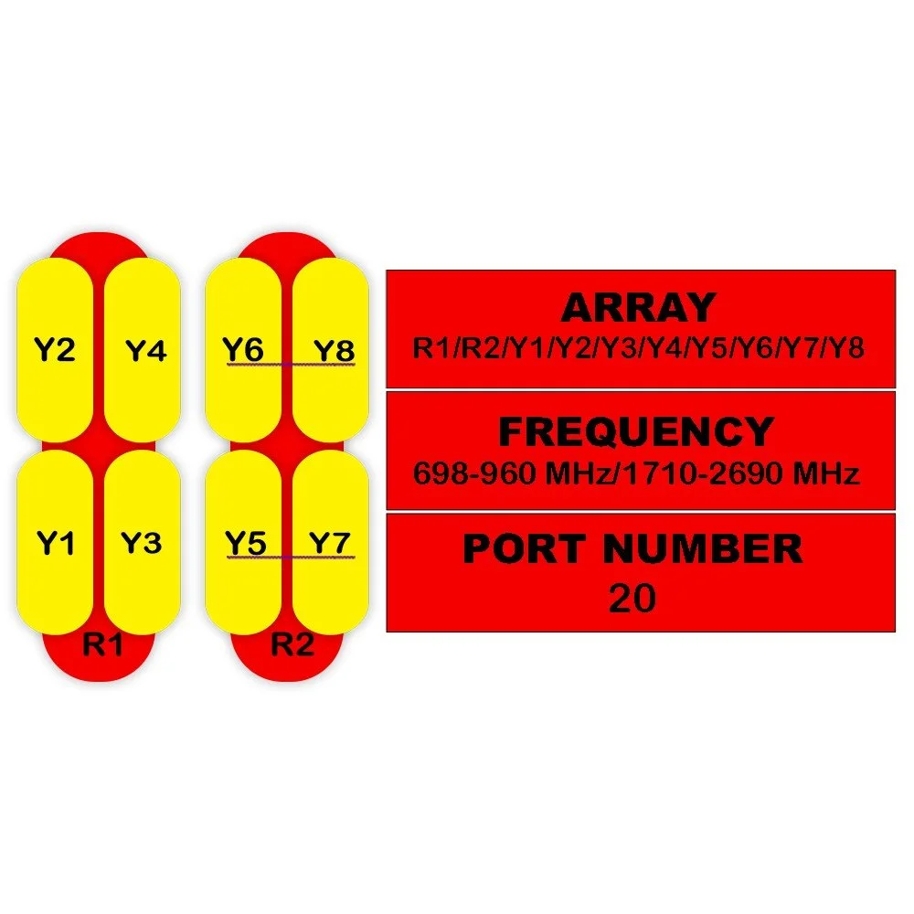
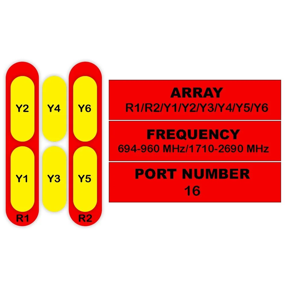
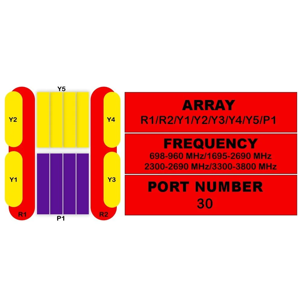
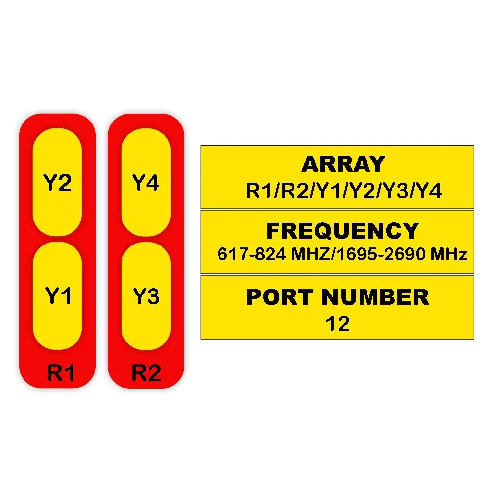
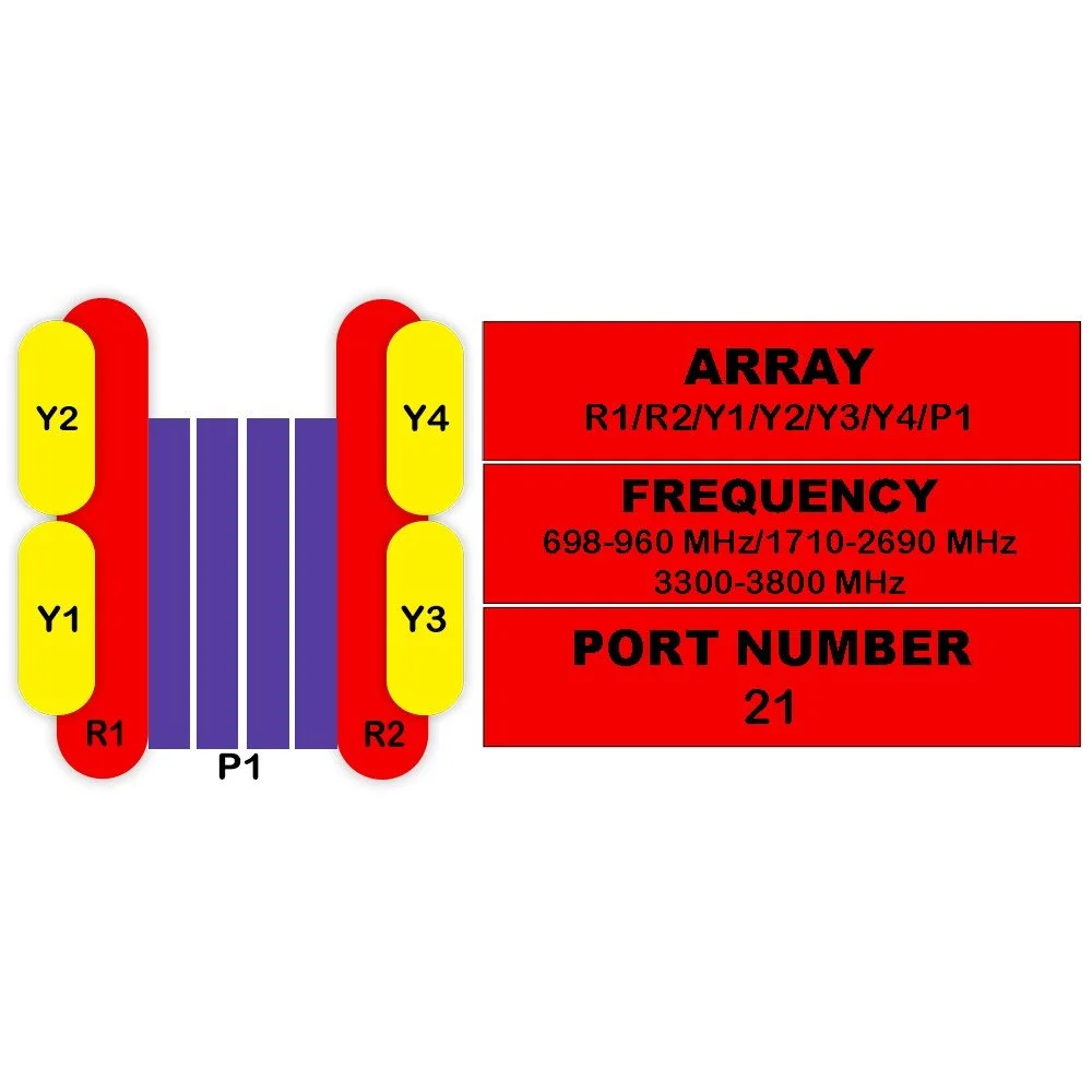
Frequency range: 690–2690 MHz, supporting low-band, mid-band LTE and FDD/TDD operations.
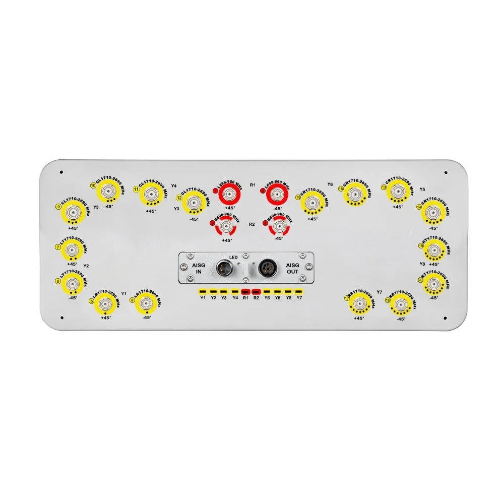
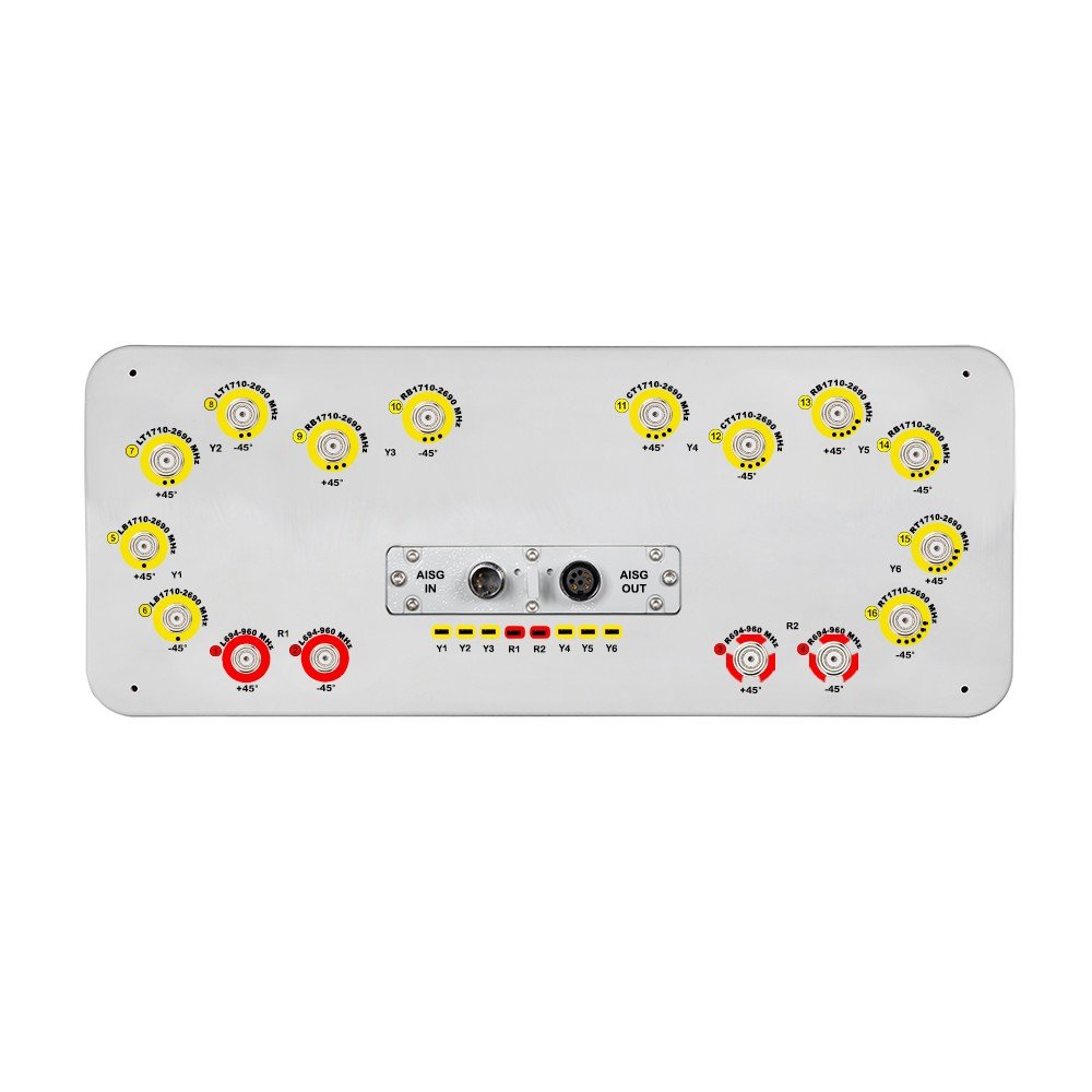
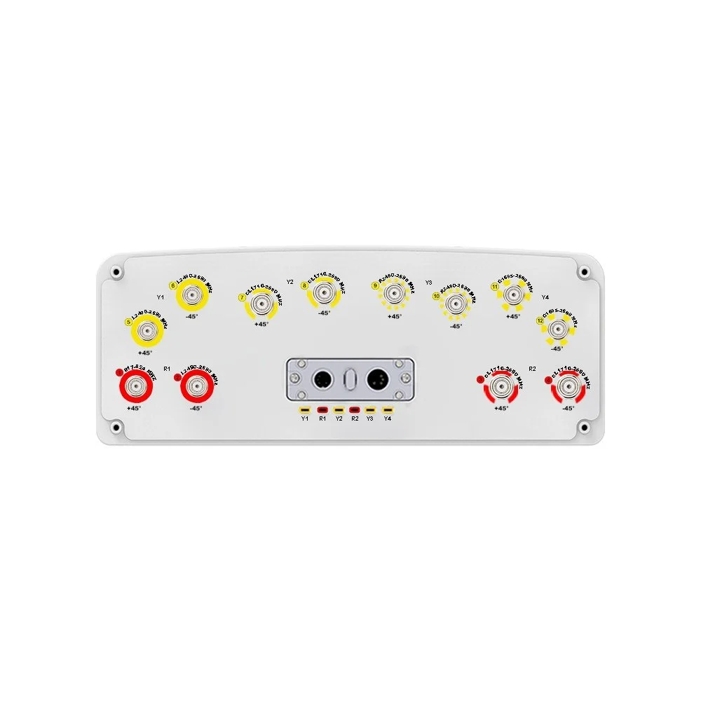
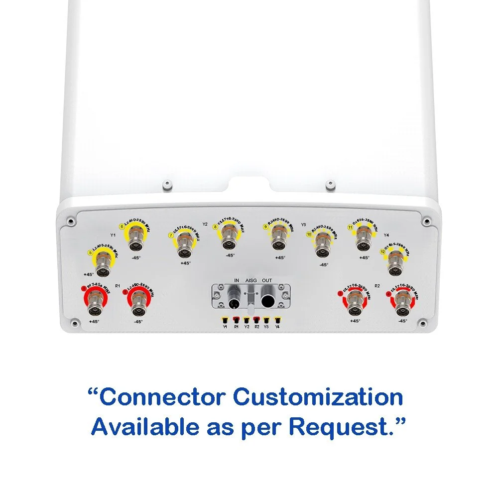
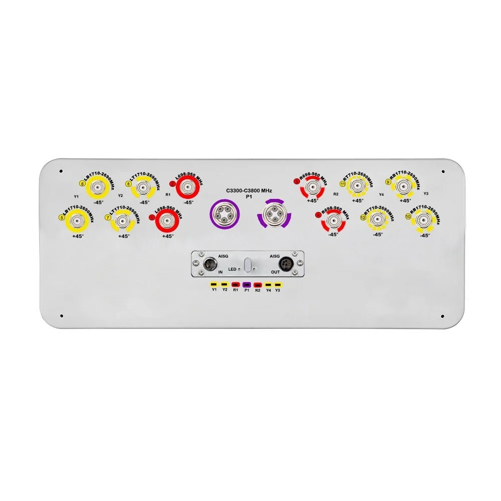
12 independent antenna ports configured for MIMO and carrier aggregation across multiple bands.
Wideband design with stable pattern control for consistent azimuth coverage across the full band.
Low port-to-port isolation loss to minimize inter-element interference and maximize MIMO efficiency.
High gain across the band with smooth gain roll-off to preserve cell edge performance.
Narrow elevation beamwidth with configurable electrical downtilt for optimal sector shaping.
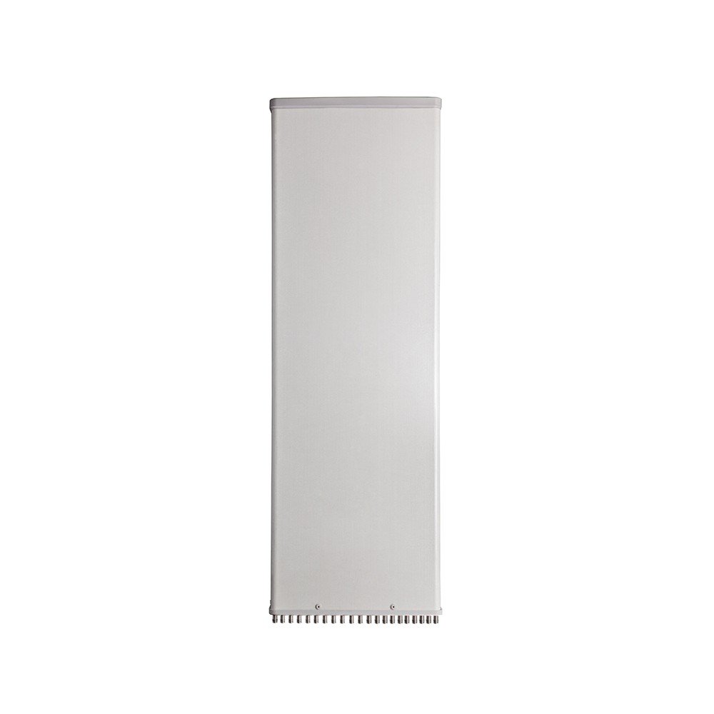
Durable radome and IP65-rated enclosure for weather resistance and long outdoor life.
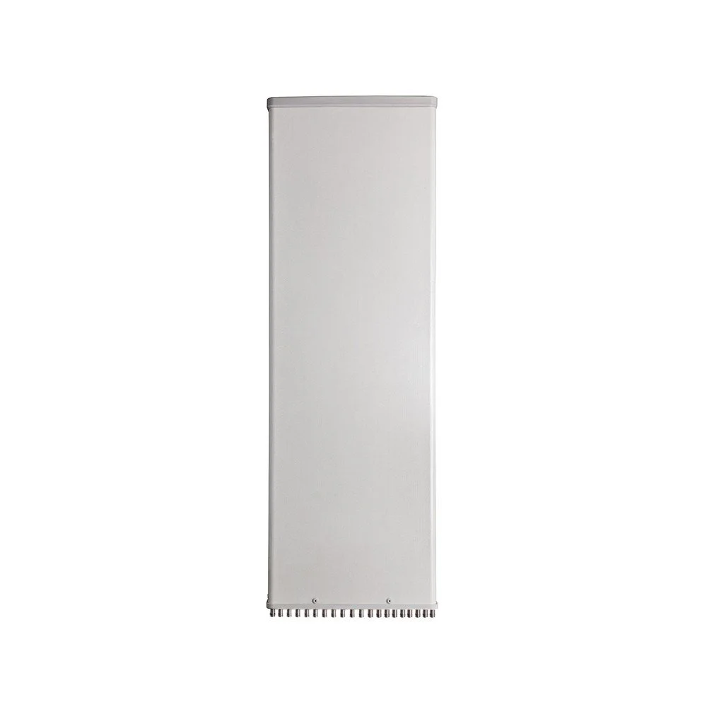
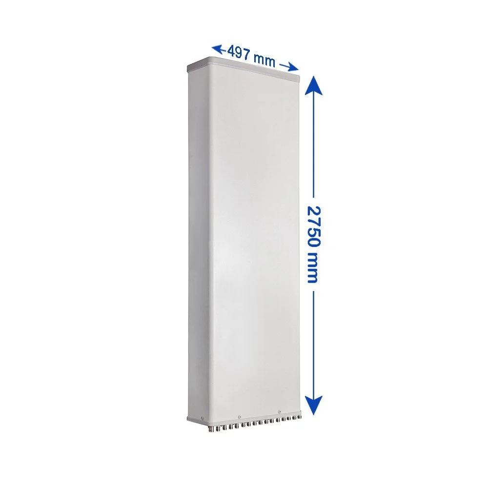
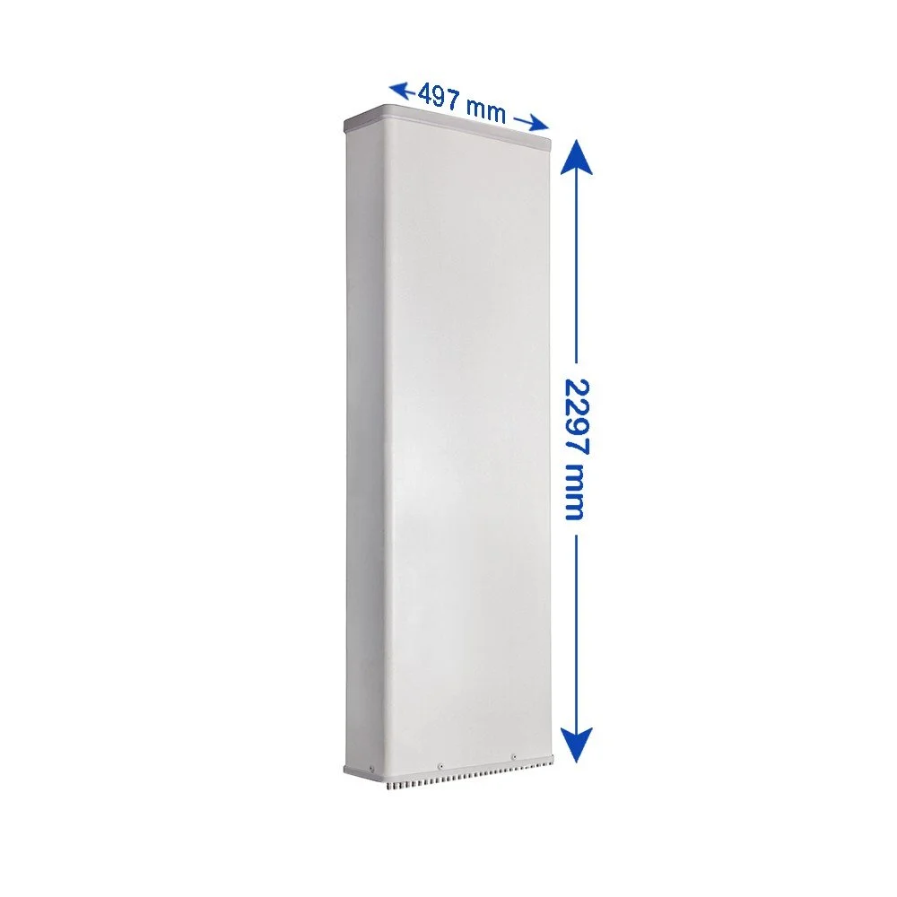
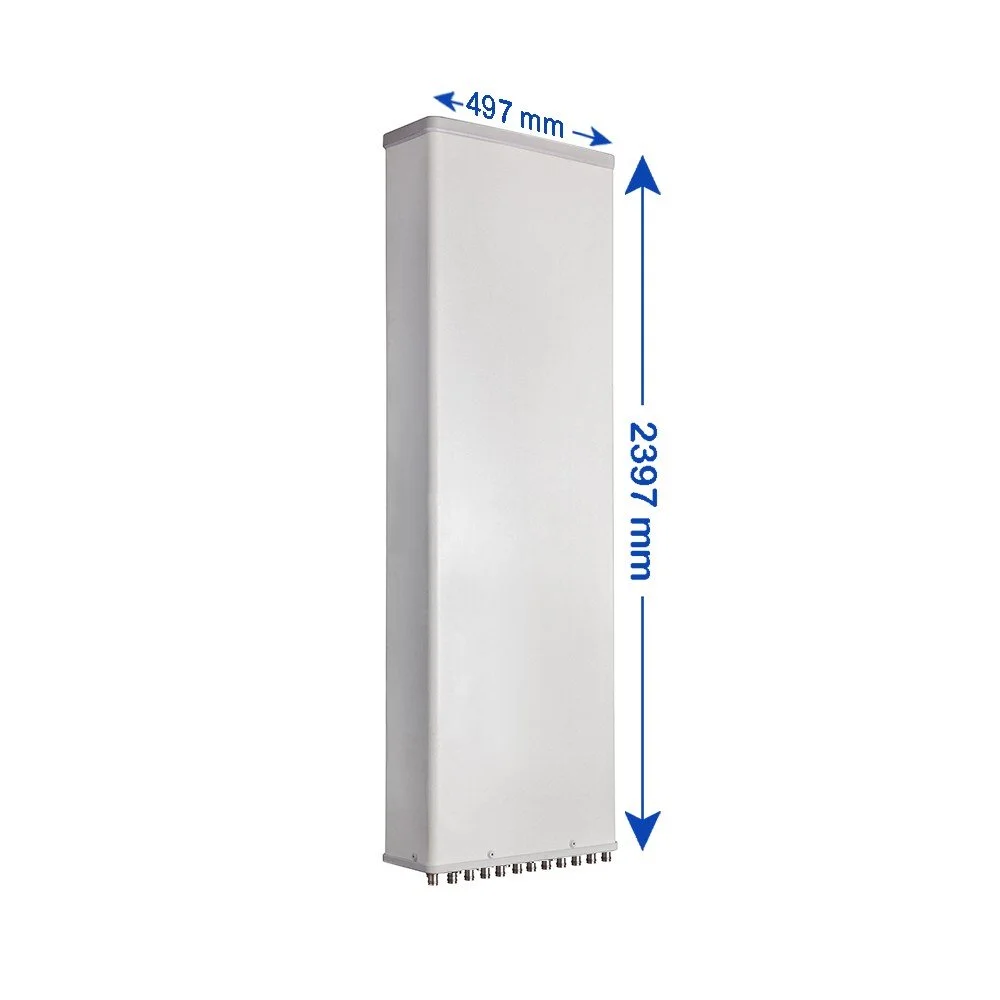
Lightweight, compact housing for rooftop, tower, pole, and wall mount installations.
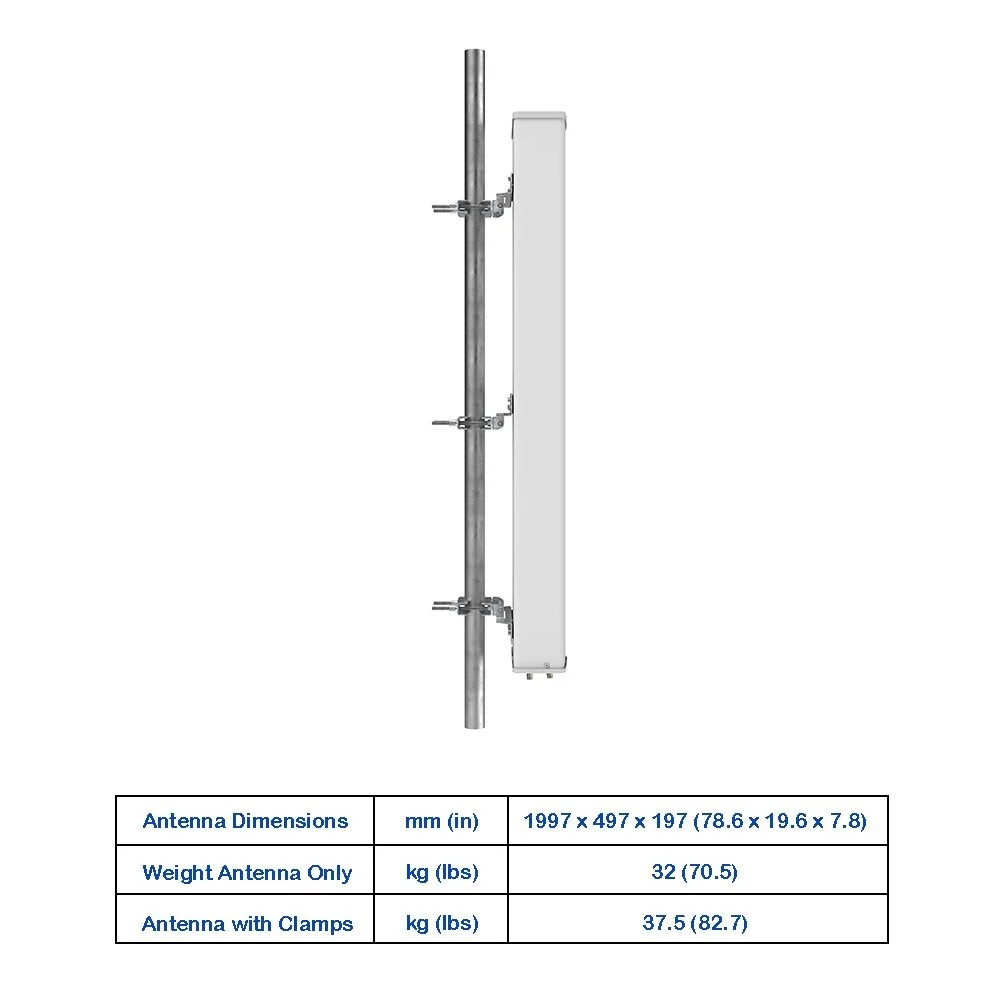
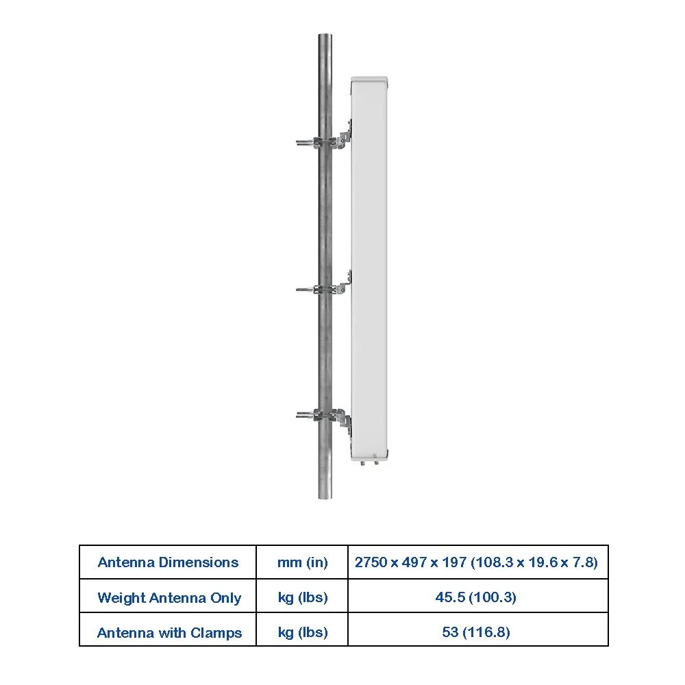
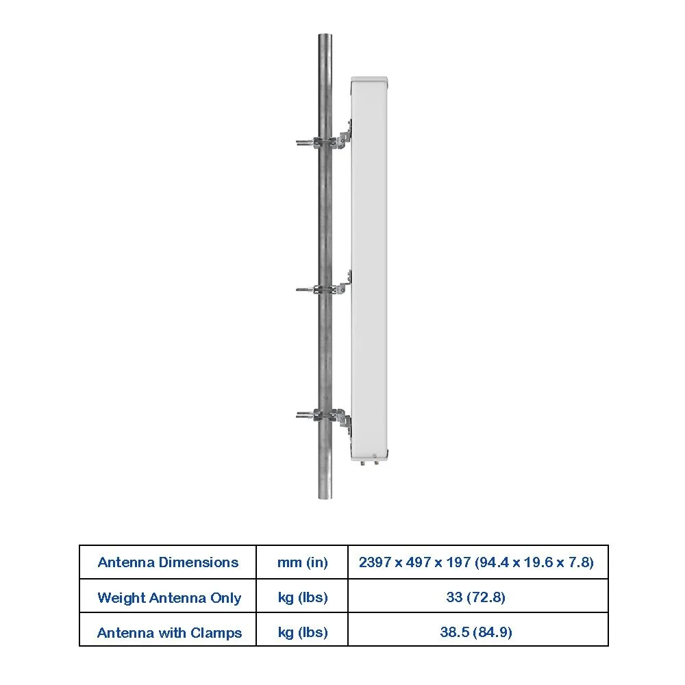
Integrated mounting bracket with mechanical tilt and azimuth adjustments; optional mounting kits available.
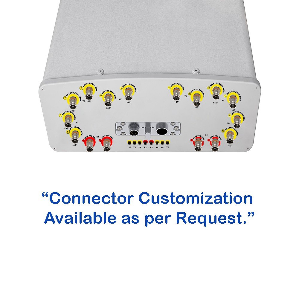
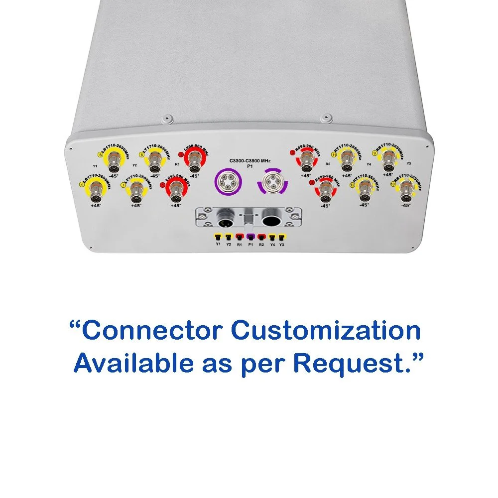
Factory-calibrated ports; individual port labeling for simplified installation and cabling.
RoHS compliant.
12-Port Panel Sector Antenna (690–2690 MHz)
Overview A high-performance 12‑port panel sector antenna engineered for multi-band cellular and private wireless deployments spanning 690–2690 MHz. Optimized for high-capacity urban and suburban sectors, this antenna delivers consistent sector coverage, low inter-port coupling, and flexible mounting for rapid deployment in 4G and 5G Non-Standalone (NSA) overlay scenarios and modern LTE networks.
Key Features :
Frequency range: 690–2690 MHz, supporting low-band, mid-band LTE and FDD/TDD operations.
12 independent antenna ports configured for MIMO and carrier aggregation across multiple bands.
Wideband design with stable pattern control for consistent azimuth coverage across the full band.
Low port-to-port isolation loss to minimize inter-element interference and maximize MIMO efficiency.
High gain across the band with smooth gain roll-off to preserve cell edge performance.
Narrow elevation beamwidth with configurable electrical downtilt for optimal sector shaping.
Durable radome and IP65-rated enclosure for weather resistance and long outdoor life.
Lightweight, compact housing for rooftop, tower, pole, and wall mount installations.
Integrated mounting bracket with mechanical tilt and azimuth adjustments; optional mounting kits available.
Factory-calibrated ports; individual port labeling for simplified installation and cabling.
RoHS compliant.

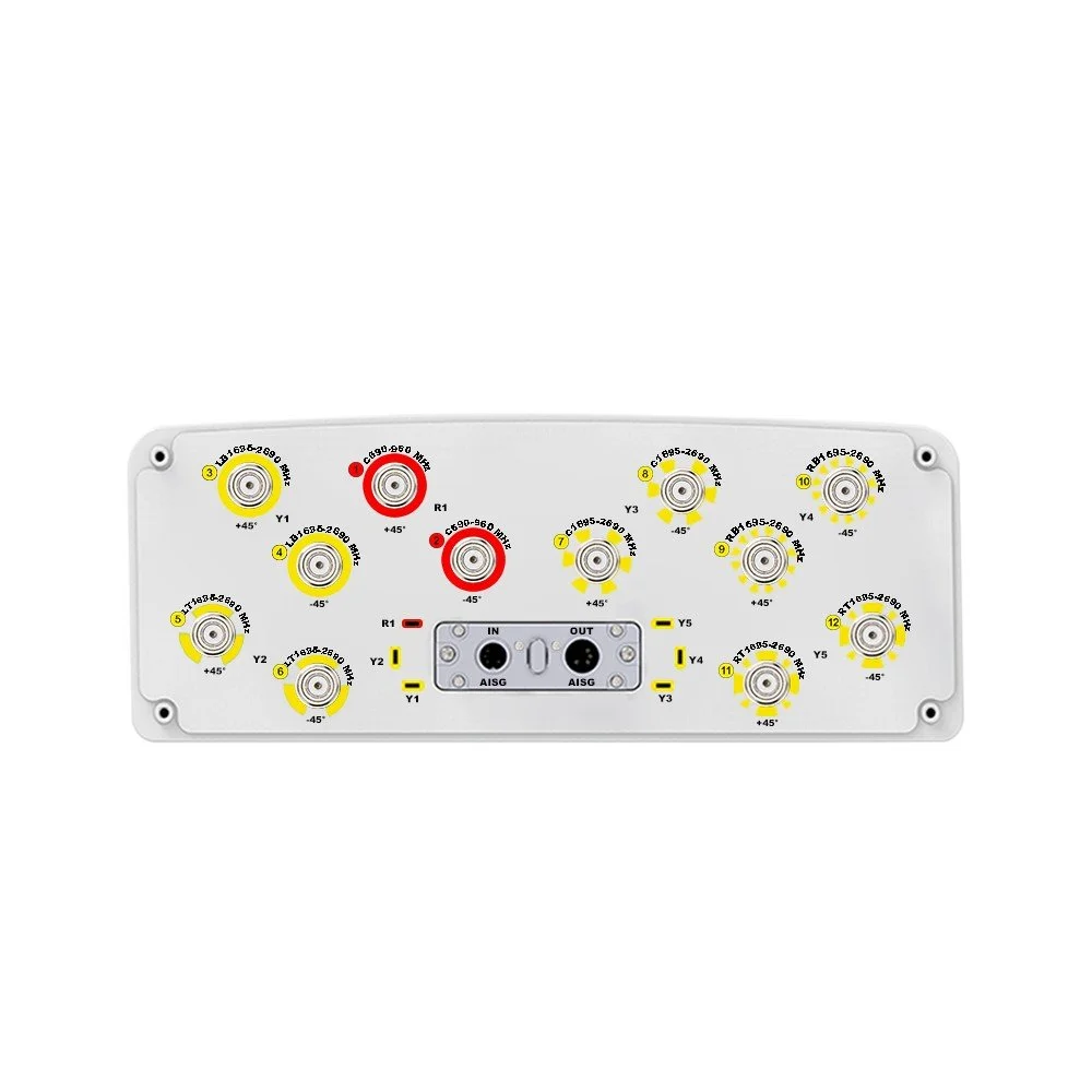 Image 1 of 6
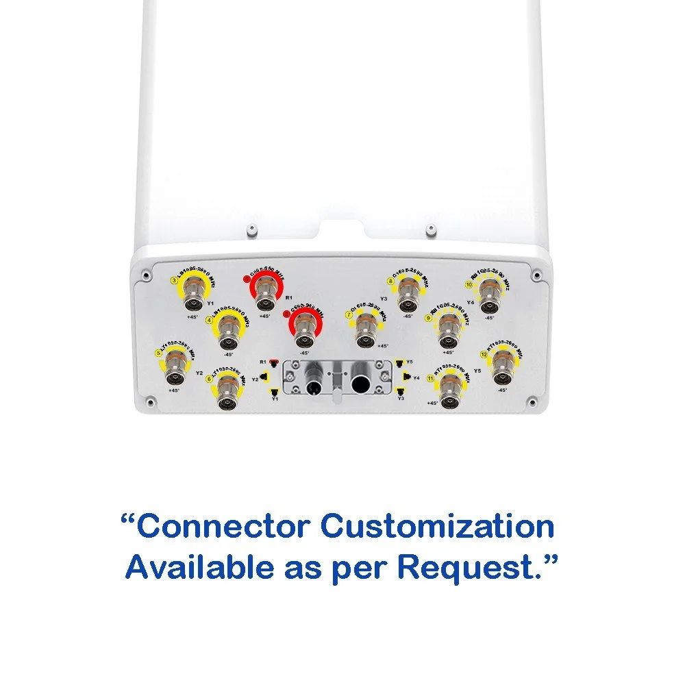 Image 2 of 6
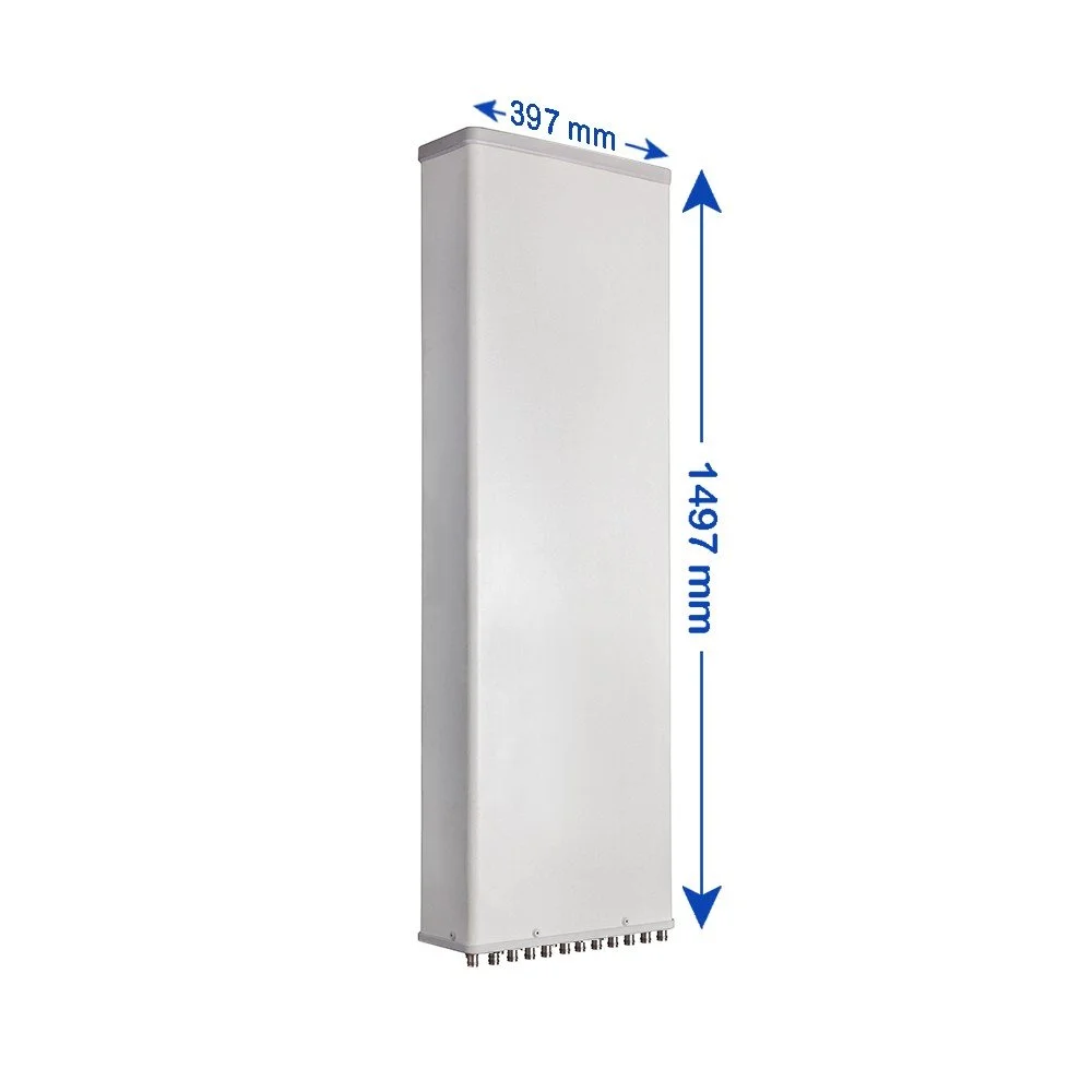 Image 3 of 6
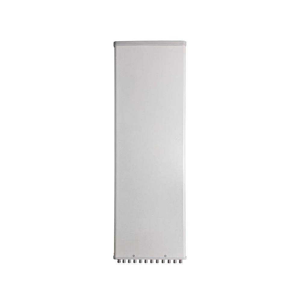 Image 4 of 6
 Image 5 of 6
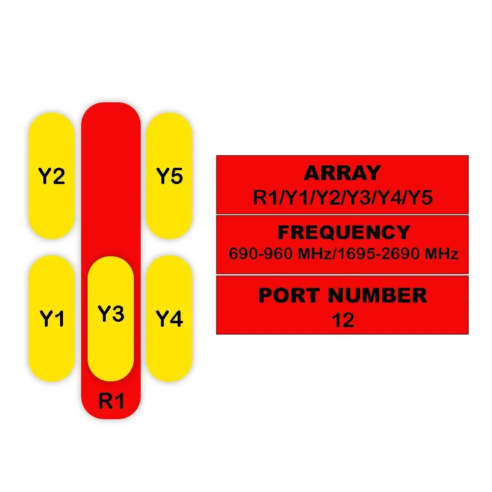 Image 6 of 6