12-Port Panel Sector Antenna (617–2690 MHz)
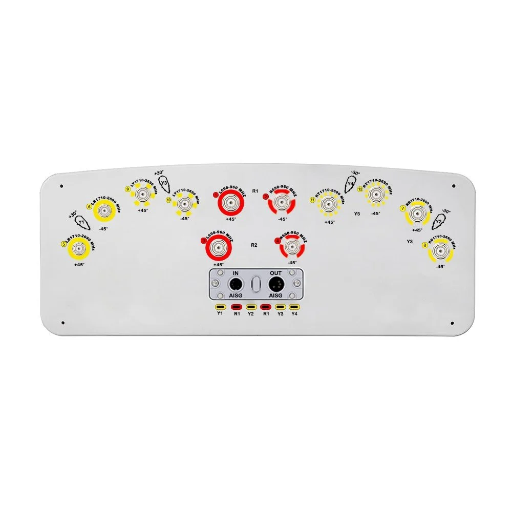
Overview An ultra-wideband, high-efficiency panel sector antenna engineered for modern macro and small cell networks. Covers 617–2690 MHz in a single aperture, supporting multi-carrier, multi-operator deployments. Twelve independent ports provide flexible MIMO, carrier aggregation, and RRH integration, reducing tower load and simplifying inventory.
Key Features :
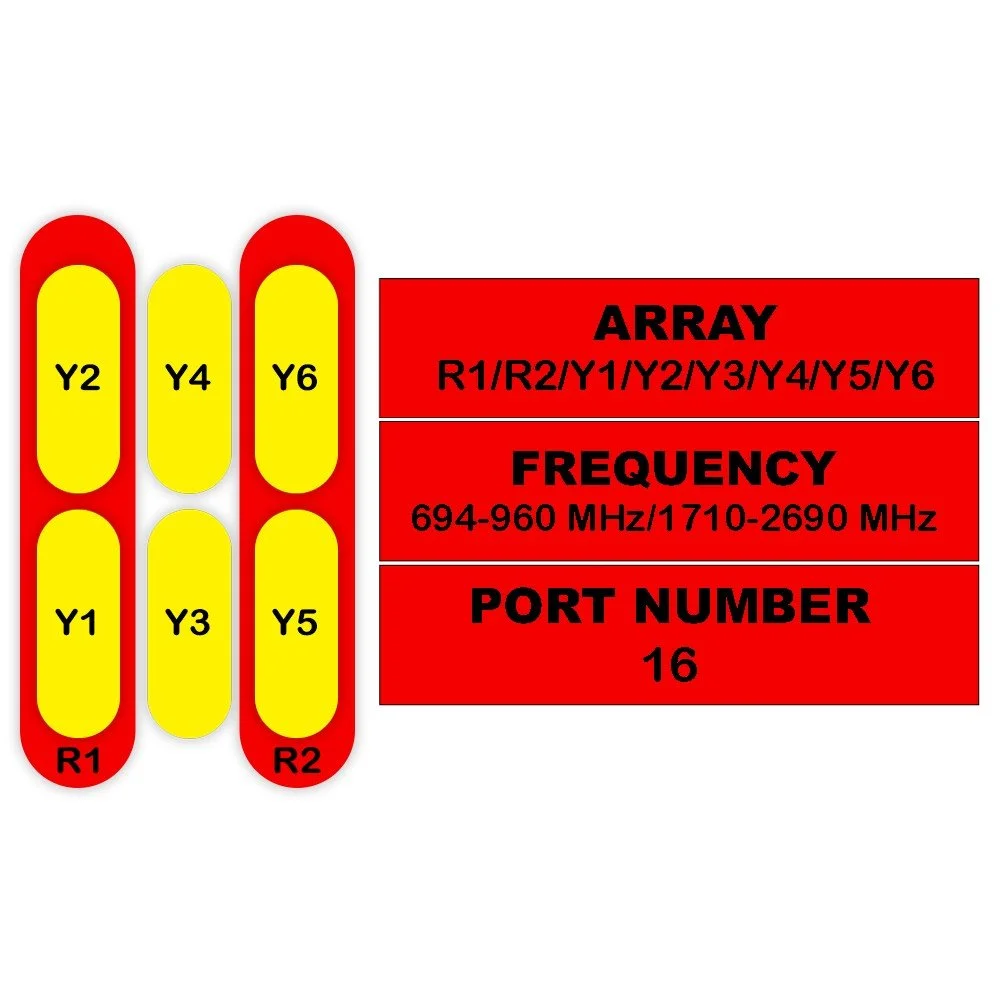
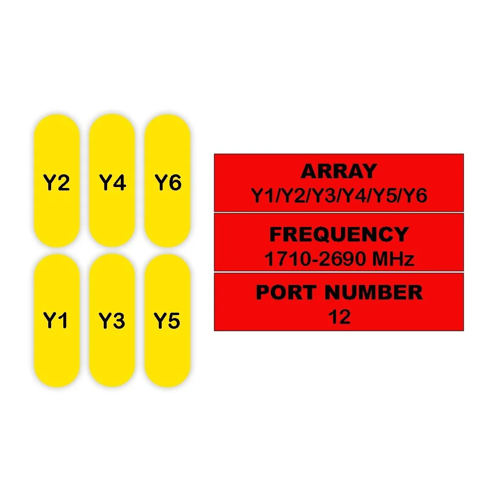
Frequency range: 617–2690 MHz (full coverage for LTE and low-mid 5G bands)
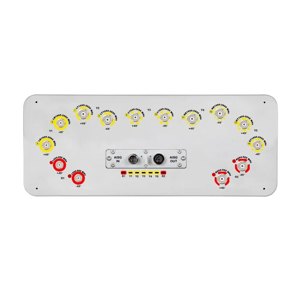
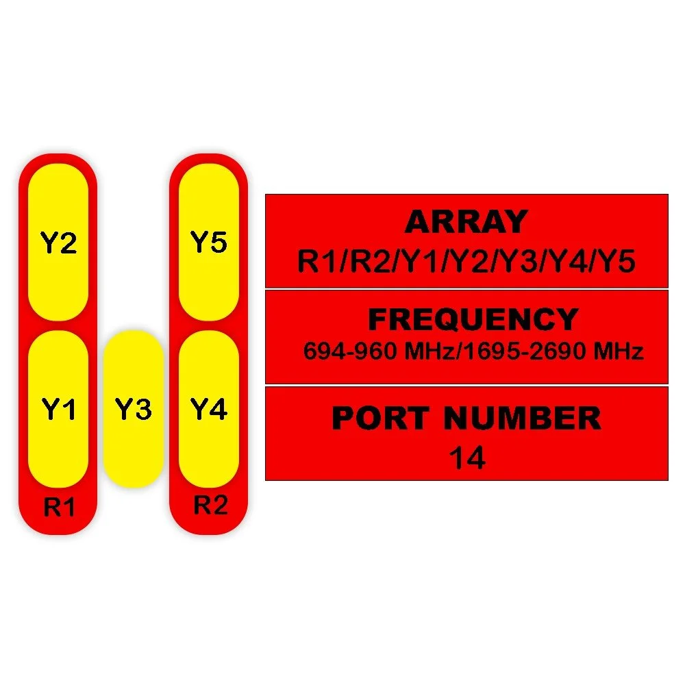
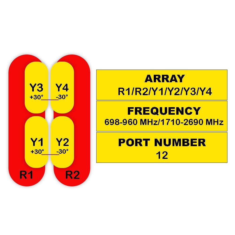
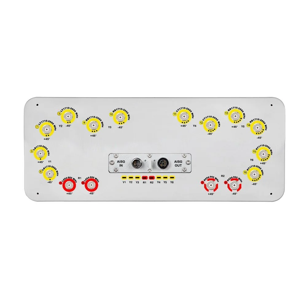
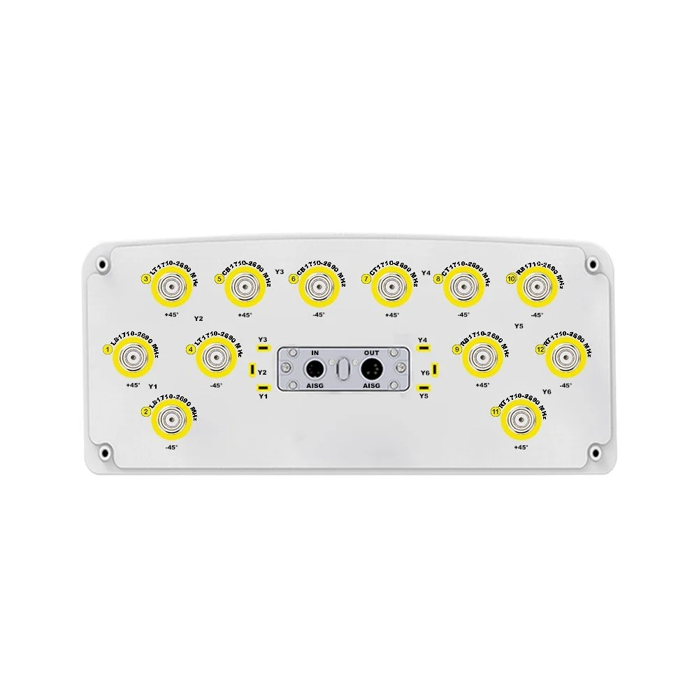
12 independent RF ports for flexible antenna mapping and MIMO configurations
Narrow vertical beamwidth for strong sectorization and reduced interference
Wide horizontal beamwidth options (60° / 90° variants available) to match cell planning
High gain across band for strong uplink/downlink performance
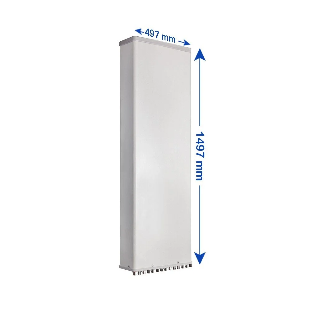
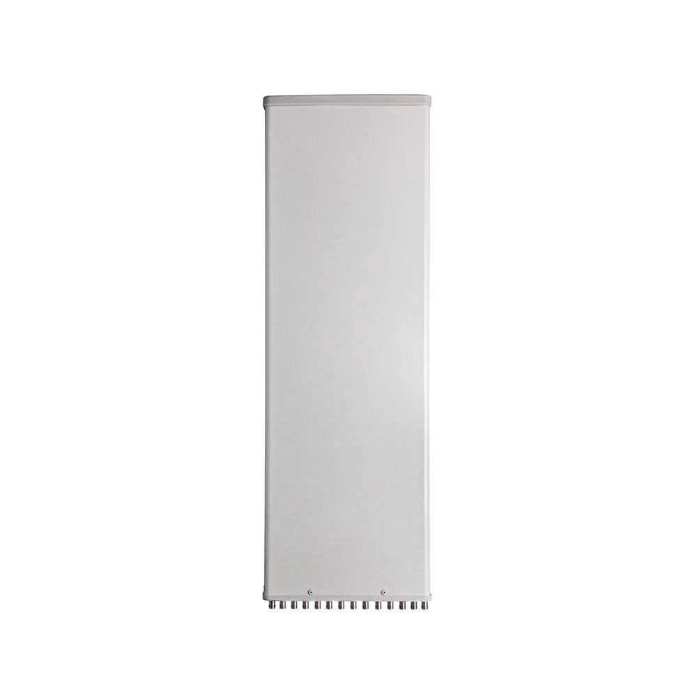
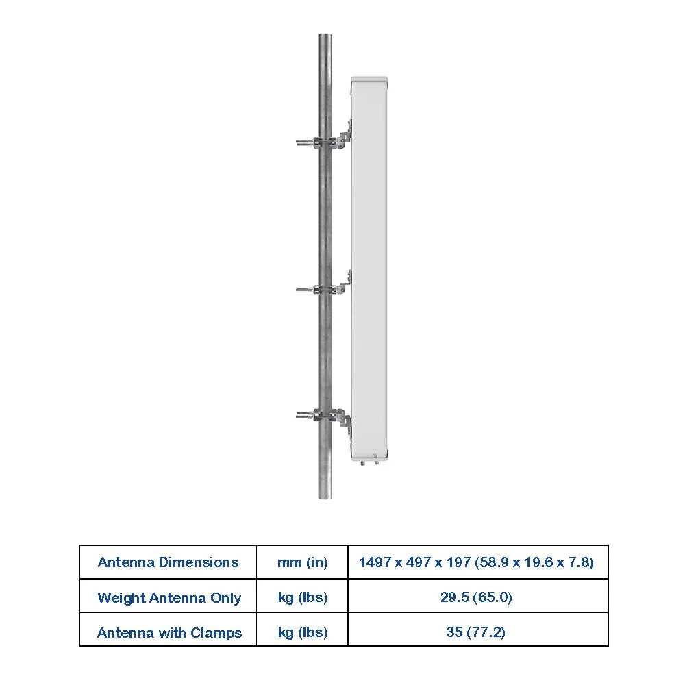
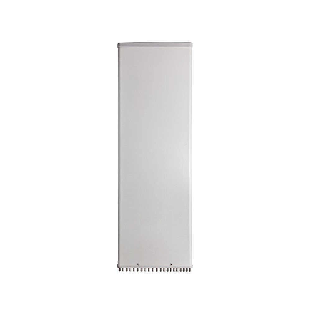
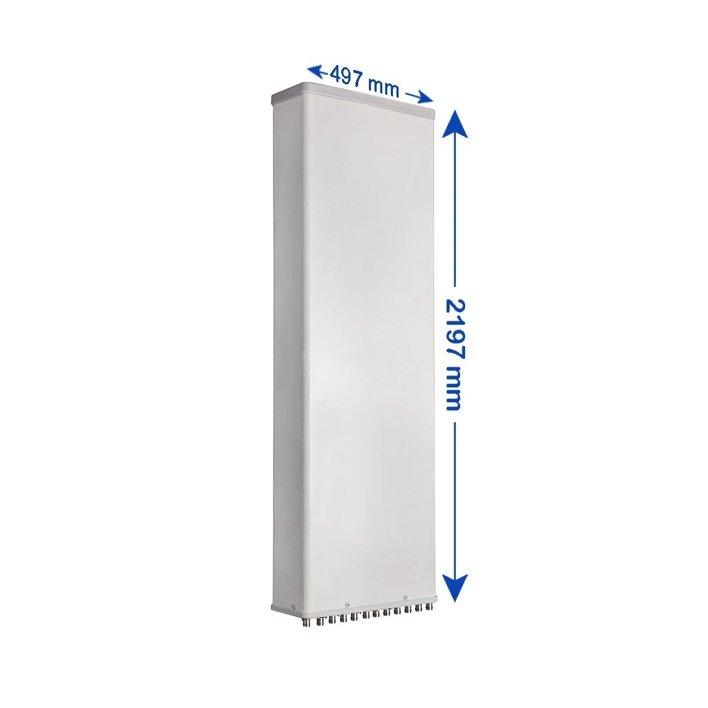
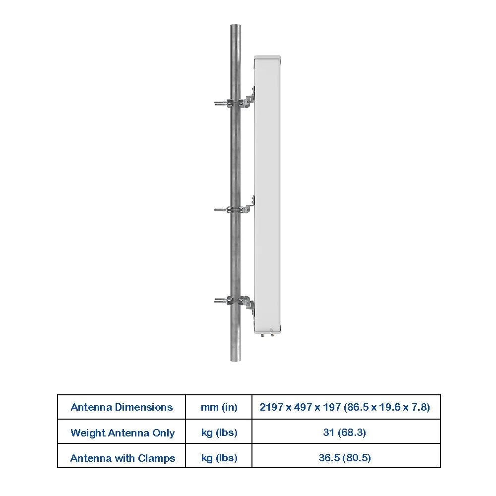
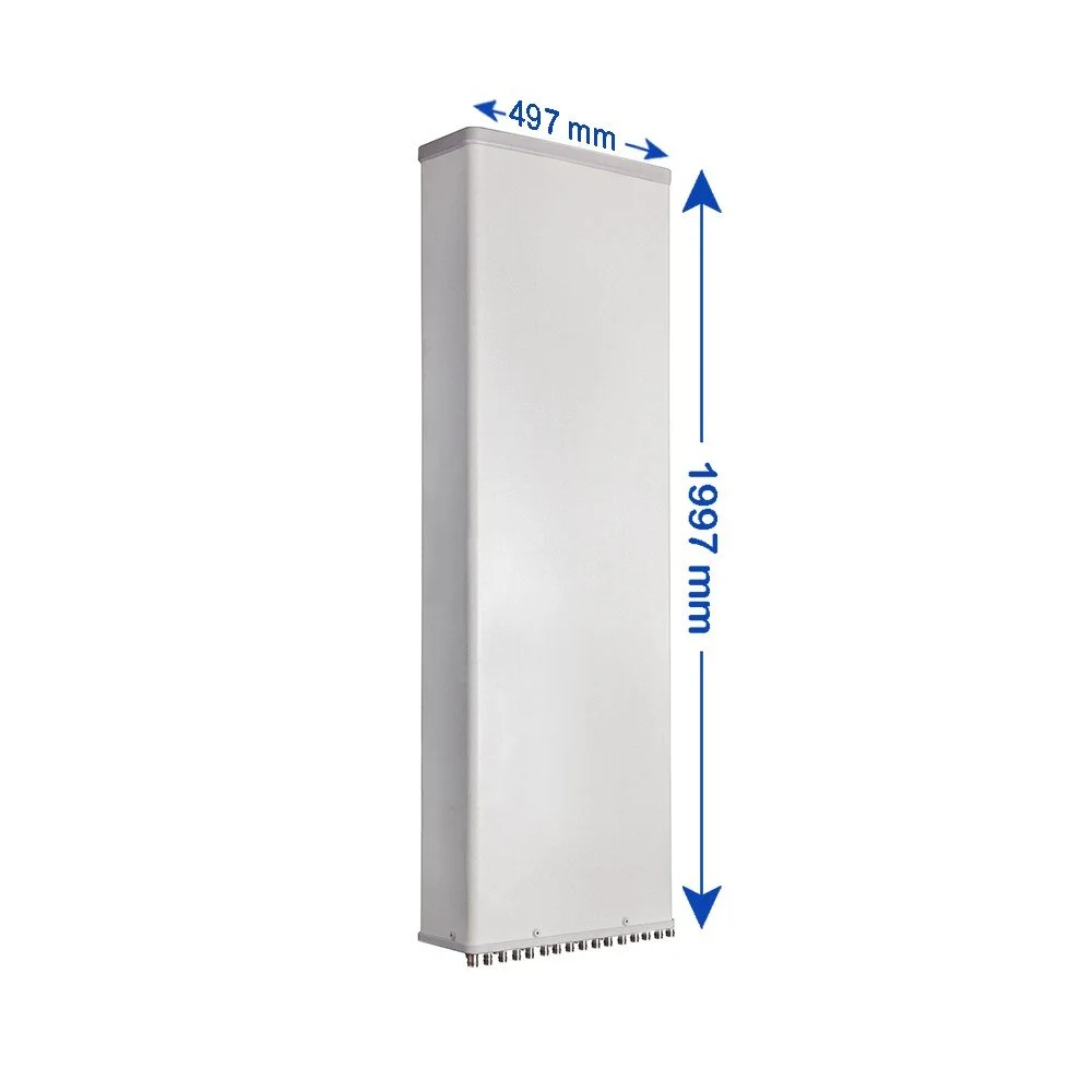
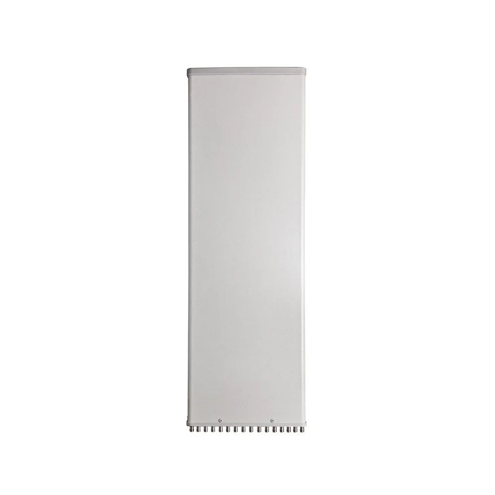
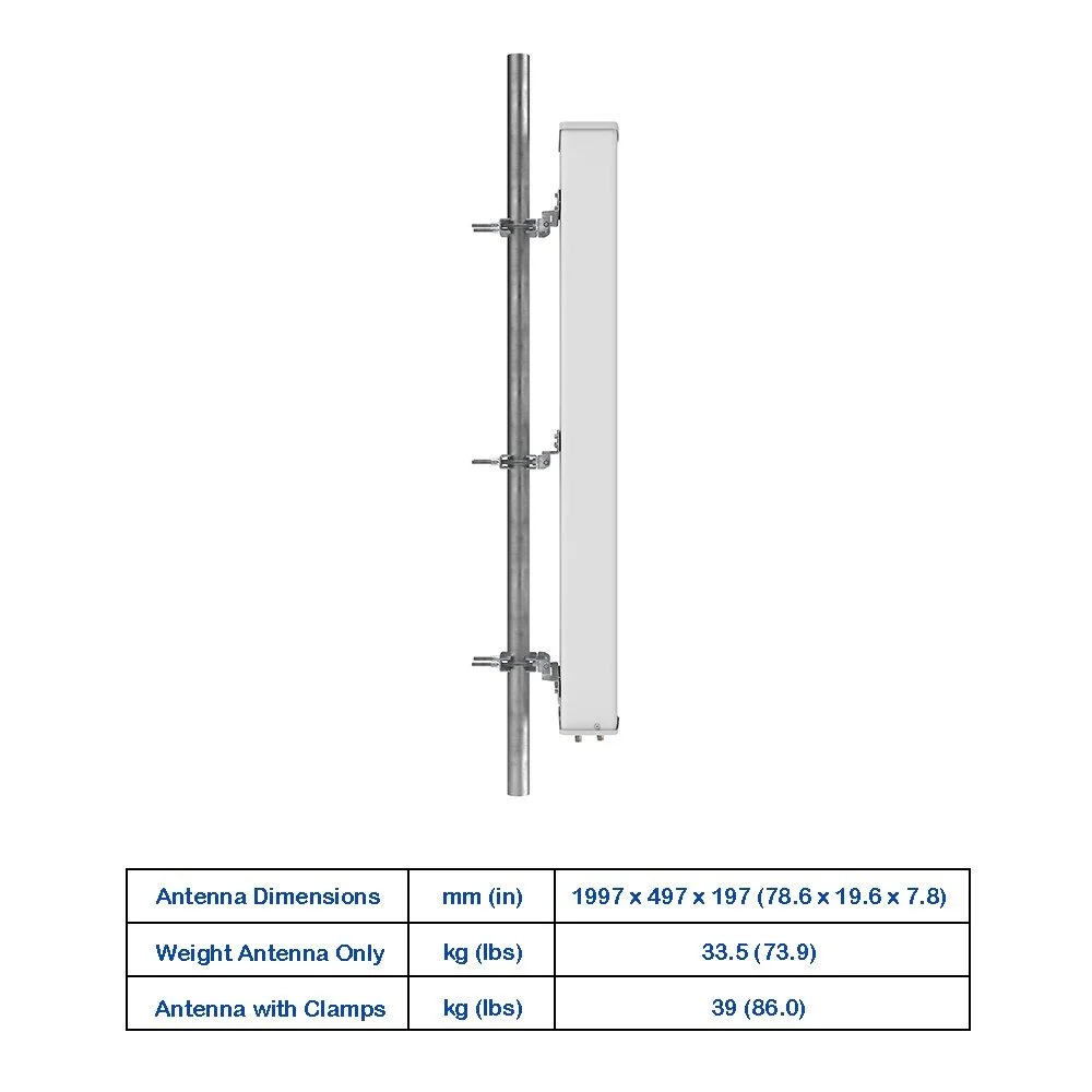
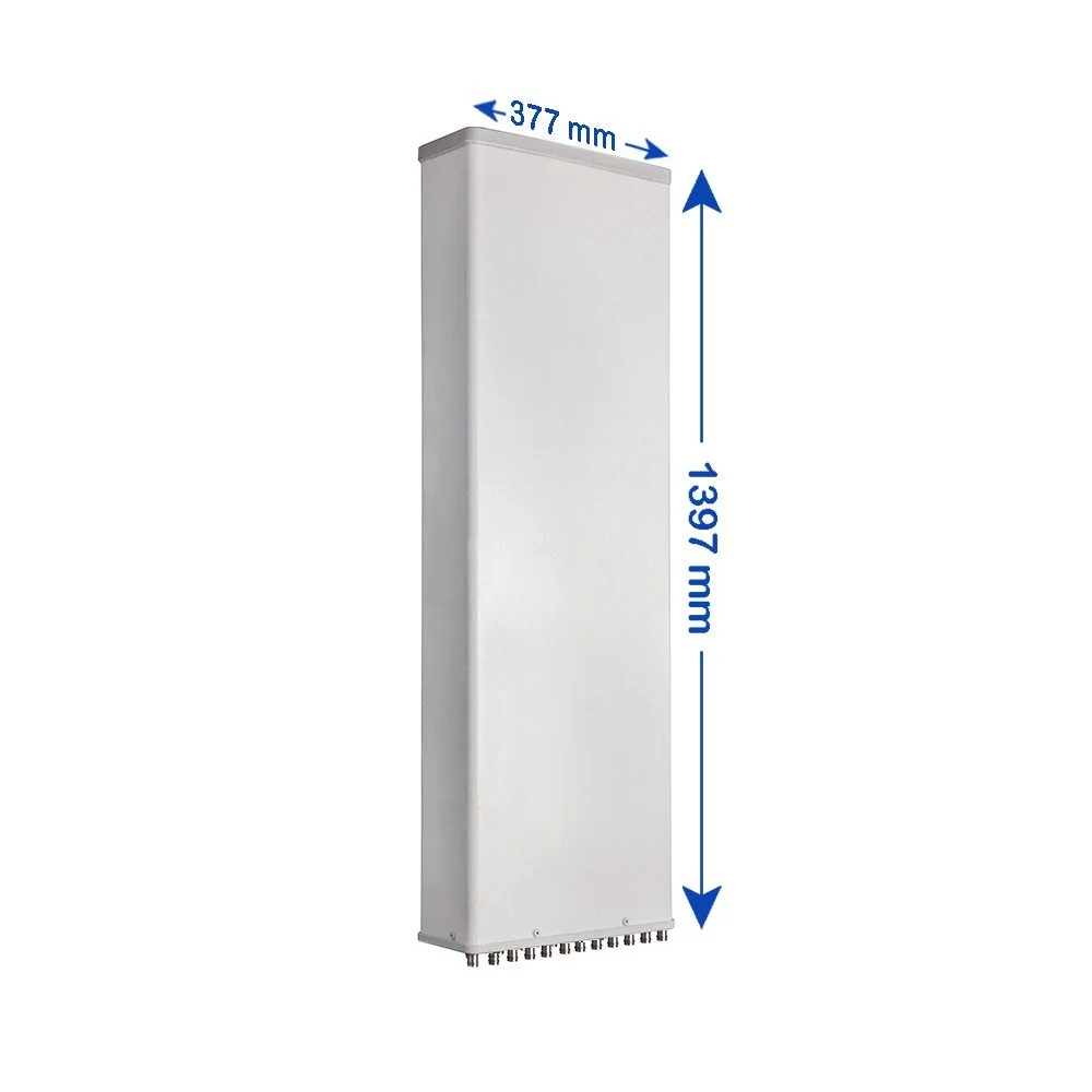
Low profile, lightweight radome for easier installation and reduced wind load
Robust IP67 weatherproofing and corrosion-resistant finish for coastal and harsh environments
Integrated tilt options: mechanical and/or remote electrical tilt (RET-ready)
Passive inter-port isolation optimized for co-located carriers and cross-polarized setups
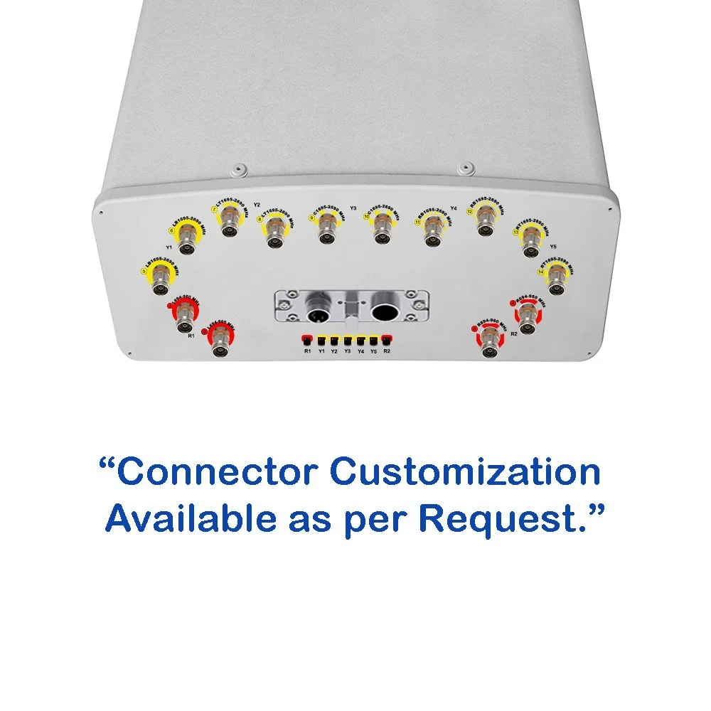
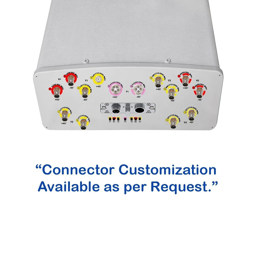
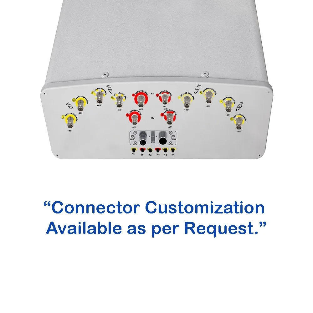
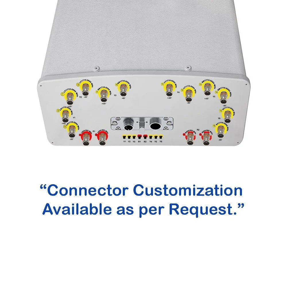
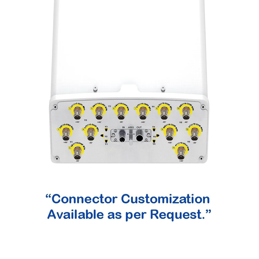
N-Type or 4.3-10 connectors available per customer spec
RoHS compliant; manufactured to industry standards for repeatable performance
12-Port Panel Sector Antenna (617–2690 MHz)
Overview An ultra-wideband, high-efficiency panel sector antenna engineered for modern macro and small cell networks. Covers 617–2690 MHz in a single aperture, supporting multi-carrier, multi-operator deployments. Twelve independent ports provide flexible MIMO, carrier aggregation, and RRH integration, reducing tower load and simplifying inventory.
Key Features :
Frequency range: 617–2690 MHz (full coverage for LTE and low-mid 5G bands)
12 independent RF ports for flexible antenna mapping and MIMO configurations
Narrow vertical beamwidth for strong sectorization and reduced interference
Wide horizontal beamwidth options (60° / 90° variants available) to match cell planning
High gain across band for strong uplink/downlink performance
Low profile, lightweight radome for easier installation and reduced wind load
Robust IP67 weatherproofing and corrosion-resistant finish for coastal and harsh environments
Integrated tilt options: mechanical and/or remote electrical tilt (RET-ready)
Passive inter-port isolation optimized for co-located carriers and cross-polarized setups
N-Type or 4.3-10 connectors available per customer spec
RoHS compliant; manufactured to industry standards for repeatable performance

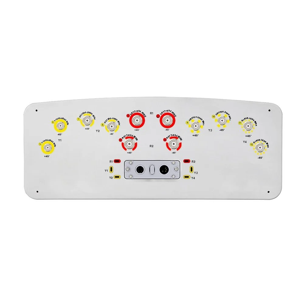 Image 1 of 6
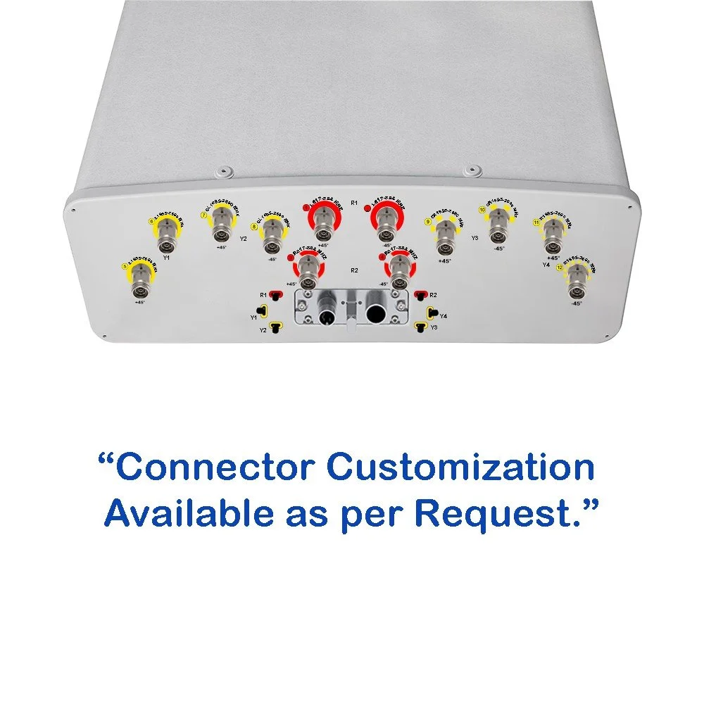 Image 2 of 6
 Image 3 of 6
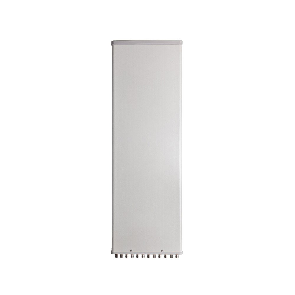 Image 4 of 6
 Image 6 of 6