Electrical Specifications
Electrical antenna specifications including gain, beamwidth,
polarization, RF performance and power handling.
| Parameter |
Sub Parameter |
Unit |
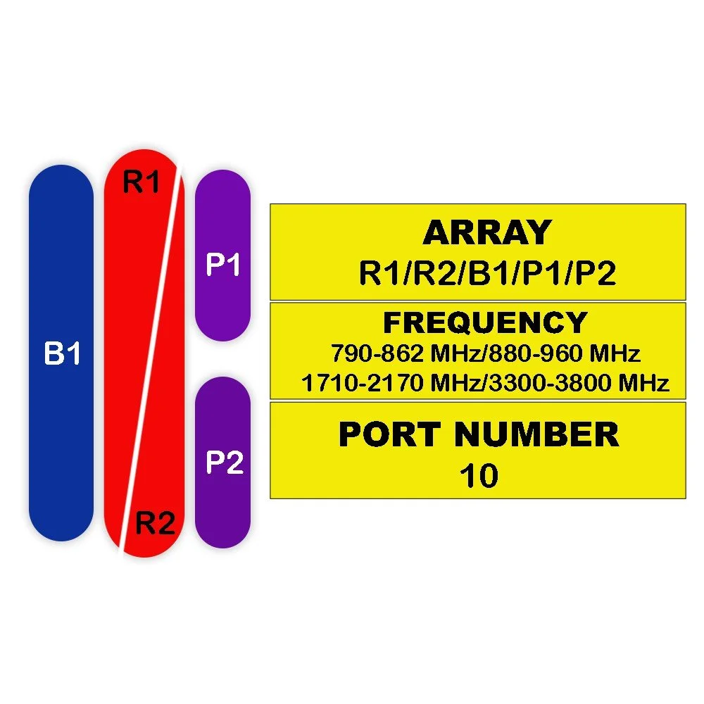
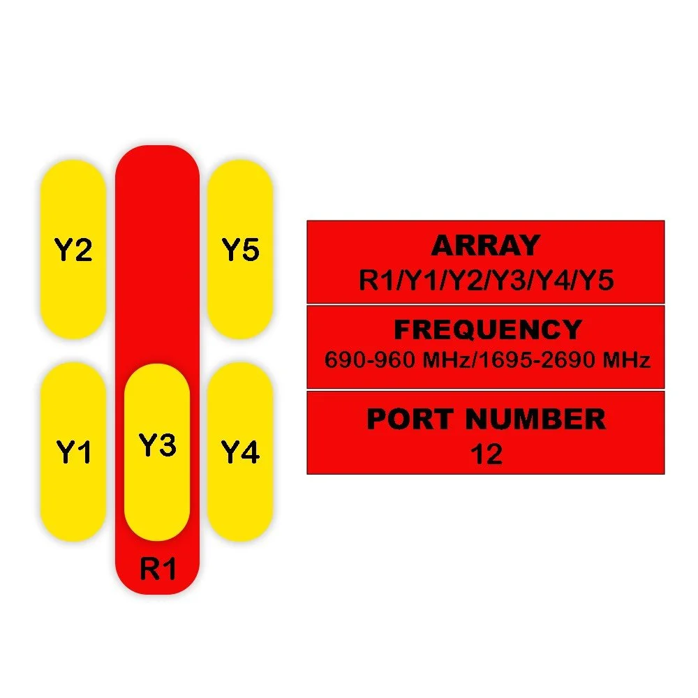
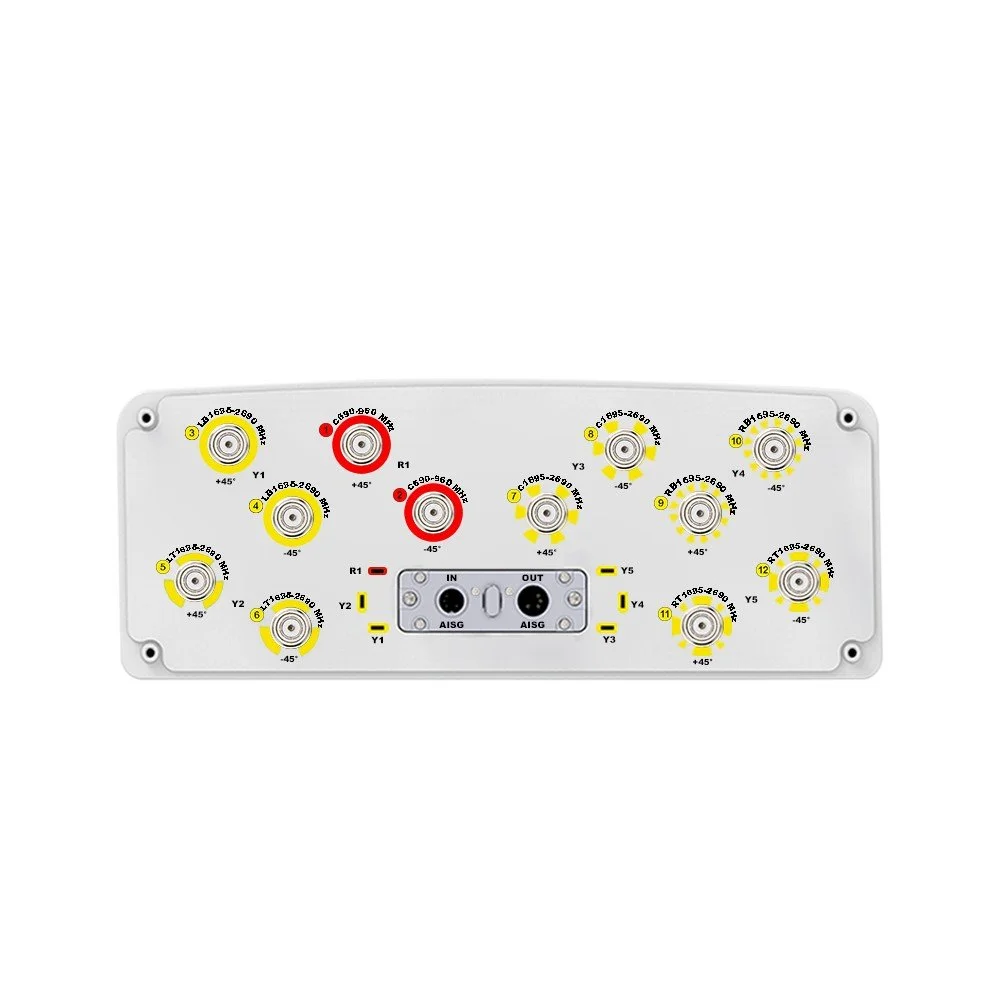
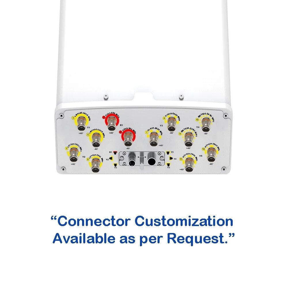
R1 / R2 |
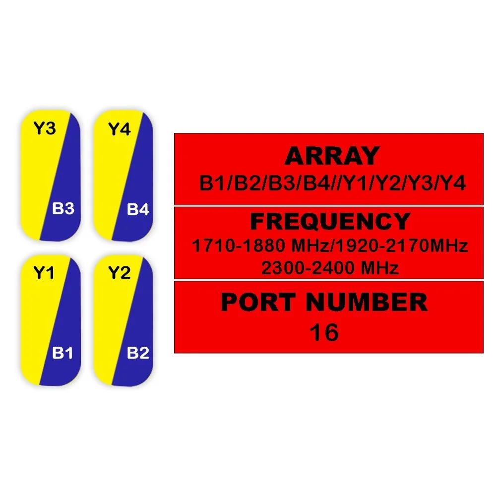
Y1 / Y2 / Y3 / Y4 |
|
|
MHz |
698-803 |
824-880 |
880-960 |
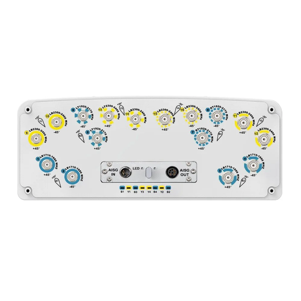
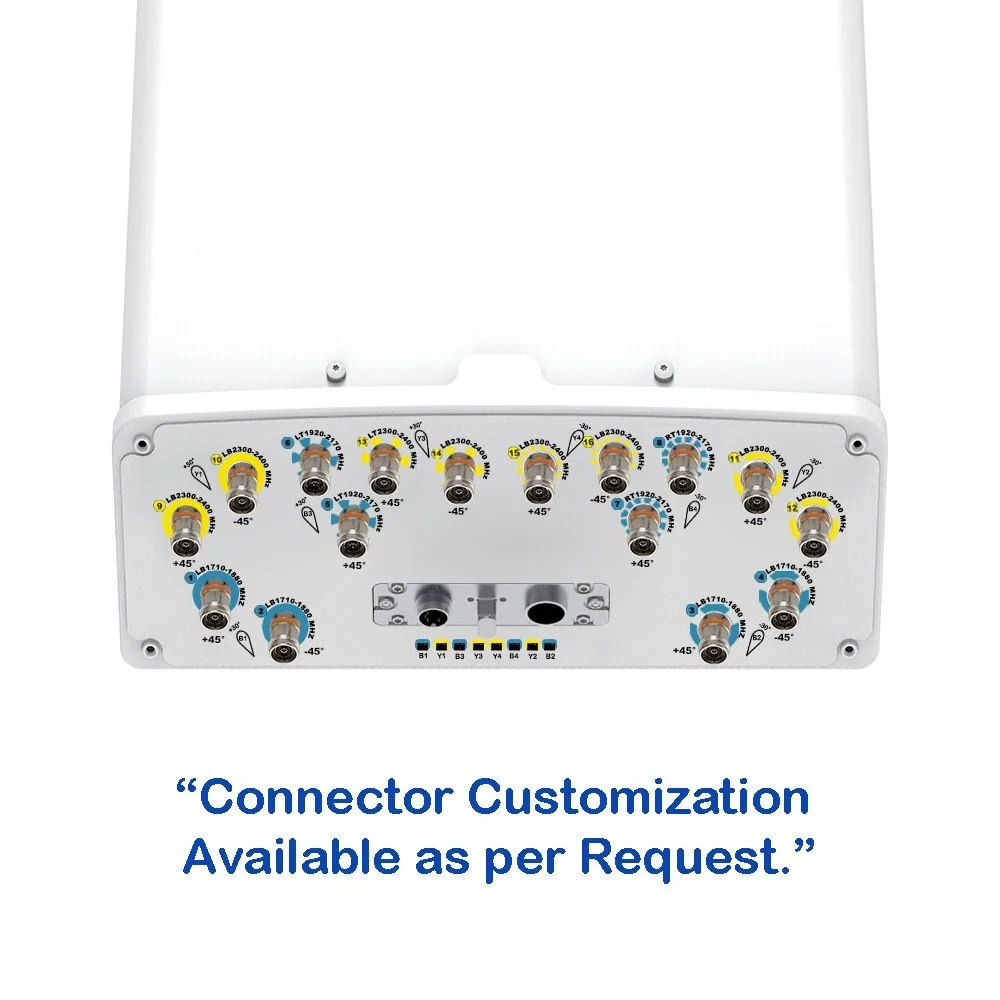
1710-1880 |
1920-2170 |
2490-2690 |
| Frequency Range |
|
MHz |
698-960 |
1710-2690 |
| Polarization |
|
— |
±45° |
±45° |
| Gain |
at Mid Tilt |
dBi |
14.8 |
15.3 |
15.6 |
17.5 |
18.1 |
18.7 |
| Over All Tilts |
dBi |
14.7 ± 0.6 |
15.2 ± 0.6 |
15.5 ± 0.6 |
17.4 ± 0.6 |
18.0 ± 0.6 |
18.6 ± 0.6 |
| Horizontal Beamwidth |
|
degree |
67 ± 6 |
65 ± 6 |
61 ± 6 |
35 ± 3 |
31 ± 3 |
25 ± 2 |
| Azimuth Beam Pointing |
|
degree |
— |
Y1 & Y3: +30; Y2 & Y4: -30 ± 3 |
| Vertical Beamwidth |
|
degree |
10.7 ± 1.1 |
9.2 ± 0.9 |
8.8 ± 0.9 |
9.8 ± 1.0 |
8.7 ± 0.9 |
6.9 ± 0.7 |
| Electrical Downtilt, Continuously Adjustable |
|
degree |
2-10 |
2-10 |
| First Upper Side Lobe Suppression |
|
dB |
≥ 15 |
≥ 15 |
≥ 15 |
> 15 |
> 15 |
> 15 |
| Front-To-Back Ratio Co-Pol, ±30° |
|
dB |
≥ 22 |
≥ 23 |
≥ 24 |
> 25 |
> 25 |
> 25 |
| Cross Polar Discrimination at Boresight |
|
dB |
≥ 15 |
≥ 15 |
≥ 15 |
> 15 |
> 15 |
> 15 |
| Isolation |
Intraband (same beam) |
dB |
≥ 25 |
≥ 25 |
| Beam-to-Beam |
dB |
— |
≥ 16 |
| Interband |
dB |
≥ 25 |
≥ 25 |
| Impedance |
|
Ohm |
50 |
50 |
| VSWR |
|
— |
< 1.5 |
< 1.5 |
| Return Loss |
|
dB |
> 14 |
> 14 |
| PIM3 (2x43 dBm Carrier) |
|
dBc |
< -150 |
< -150 |
| Lightning Protection |
|
— |
DC Ground |
DC Ground |
| Maximum Average Input Power per Port, at 50° C Ambient Temperature |
|
Watts |
250 |
200 |

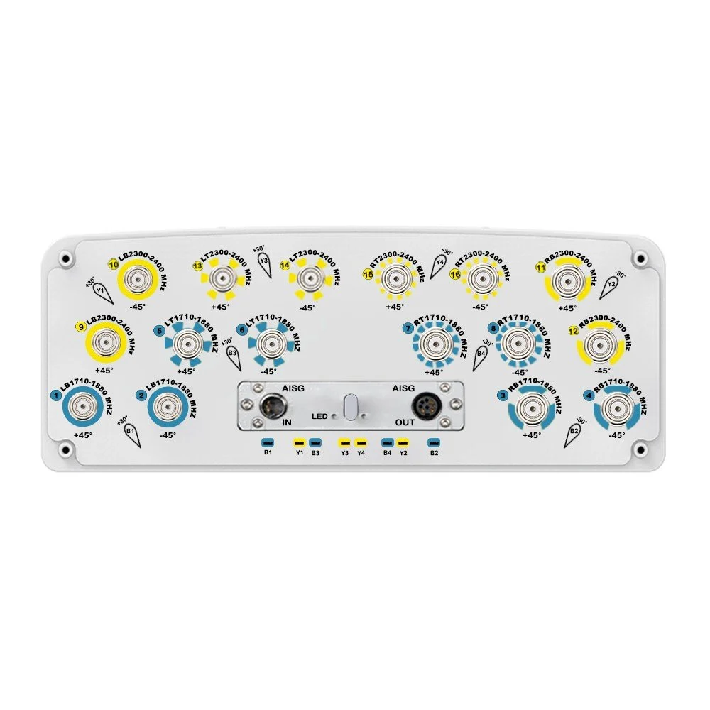
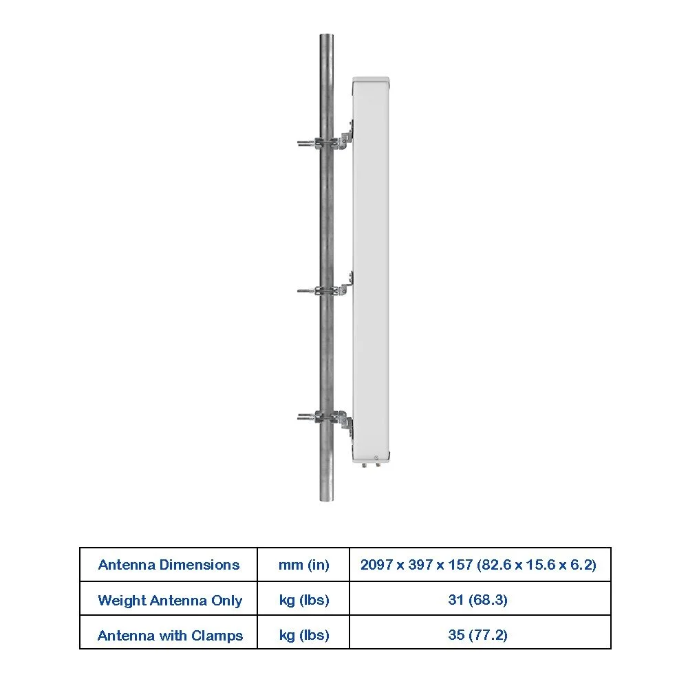
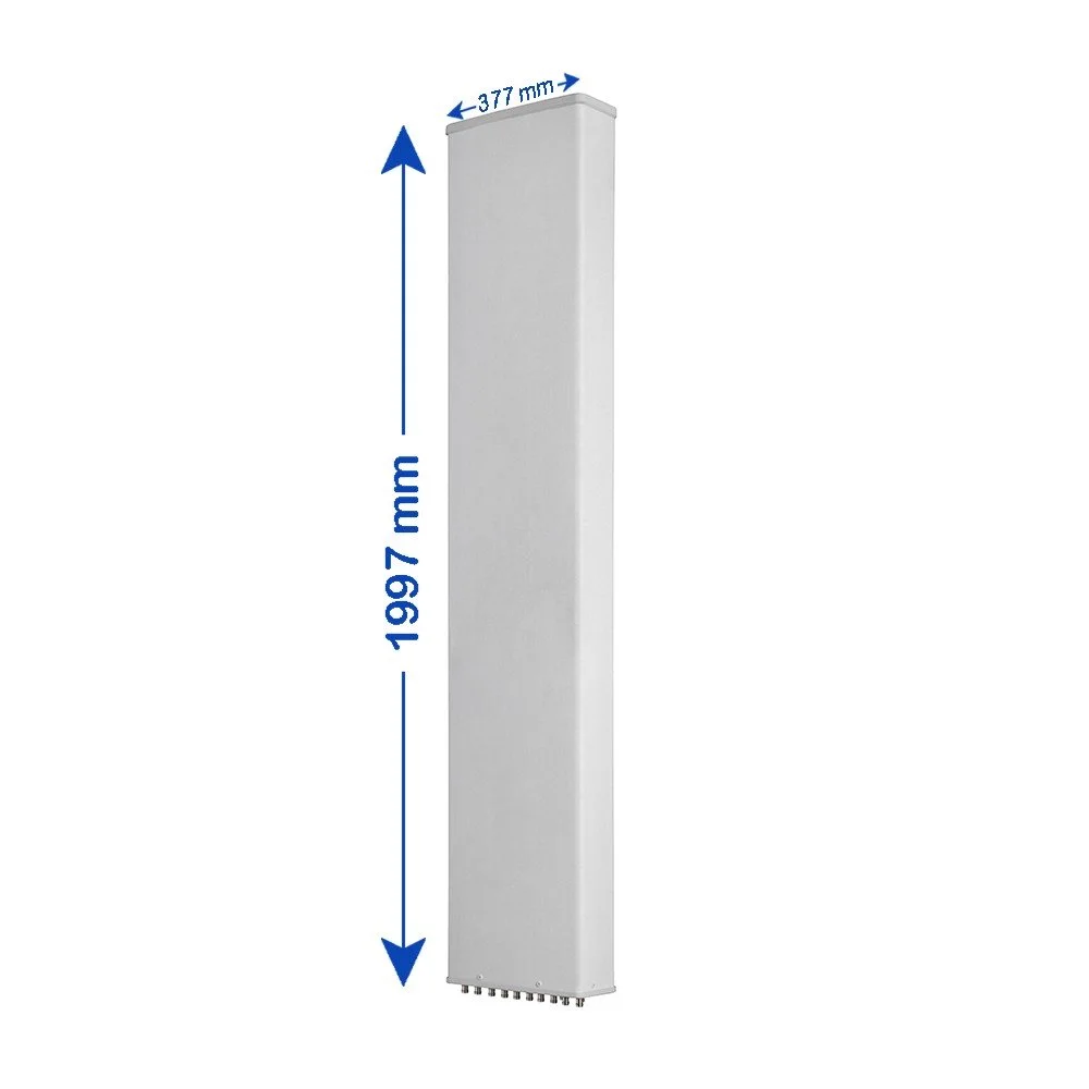
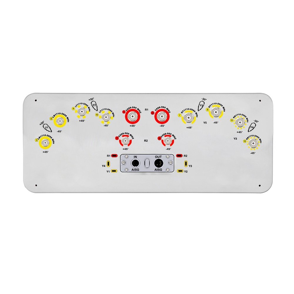 Image 1 of 6
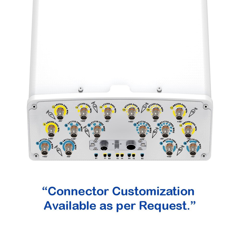
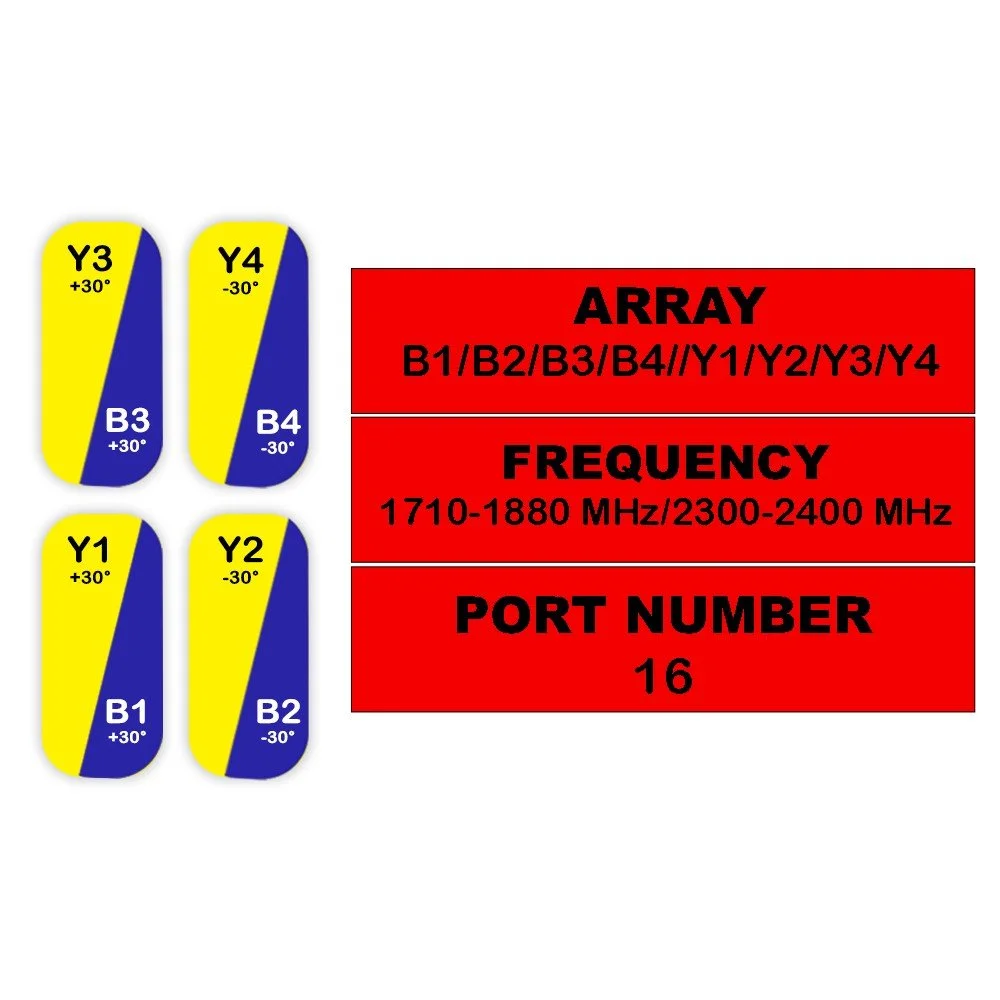
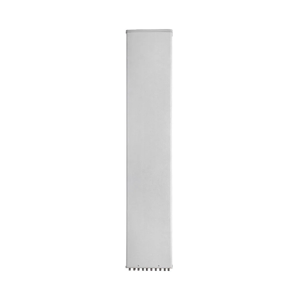
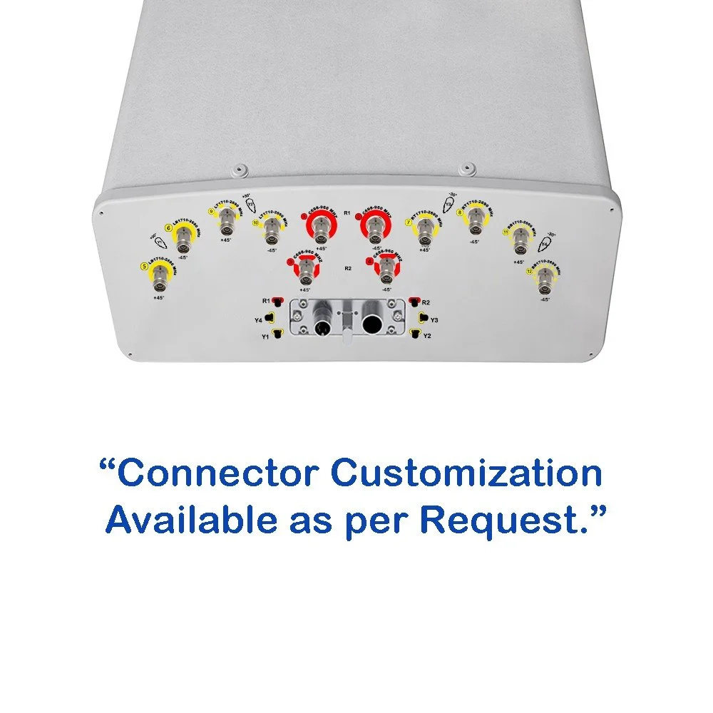 Image 2 of 6
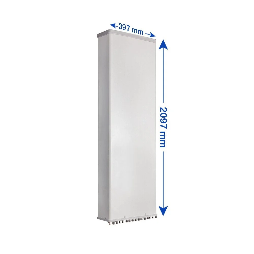
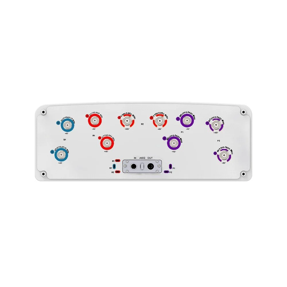
 Image 3 of 6
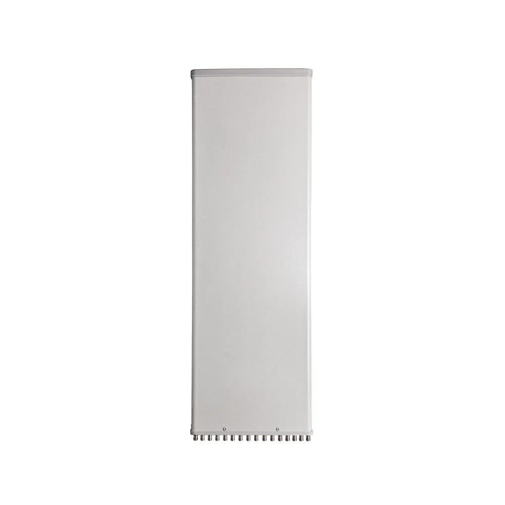
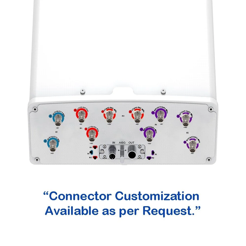
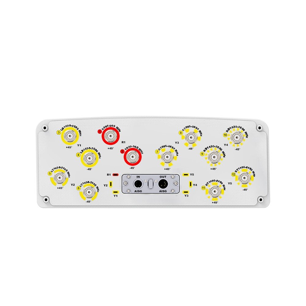
 Image 4 of 6
 Image 5 of 6
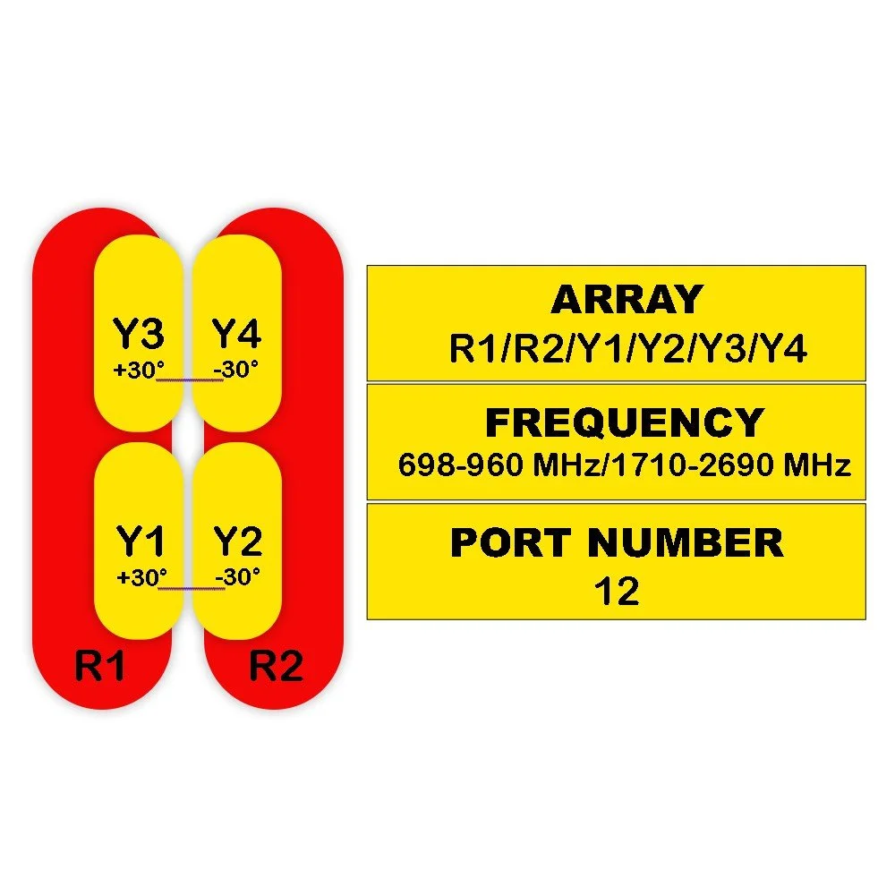 Image 6 of 6