 Image 1 of 6
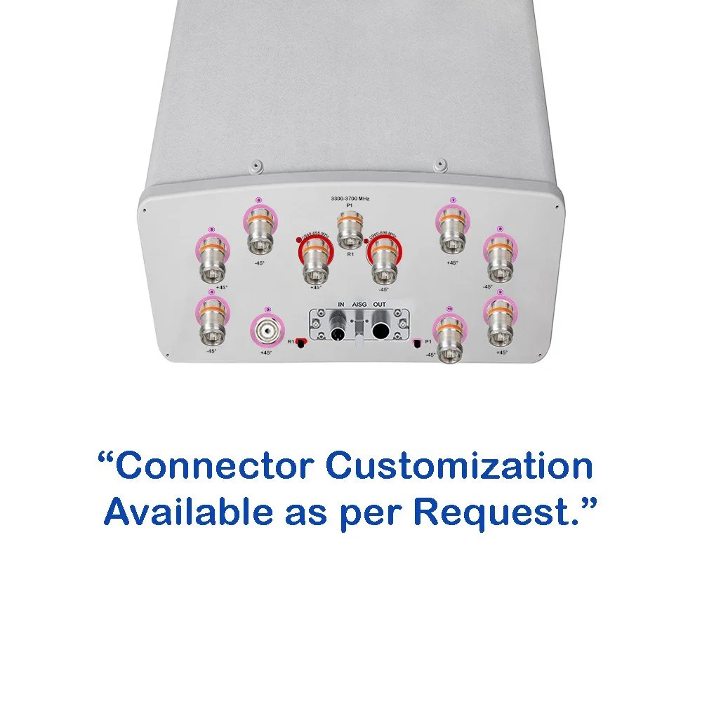 Image 2 of 6
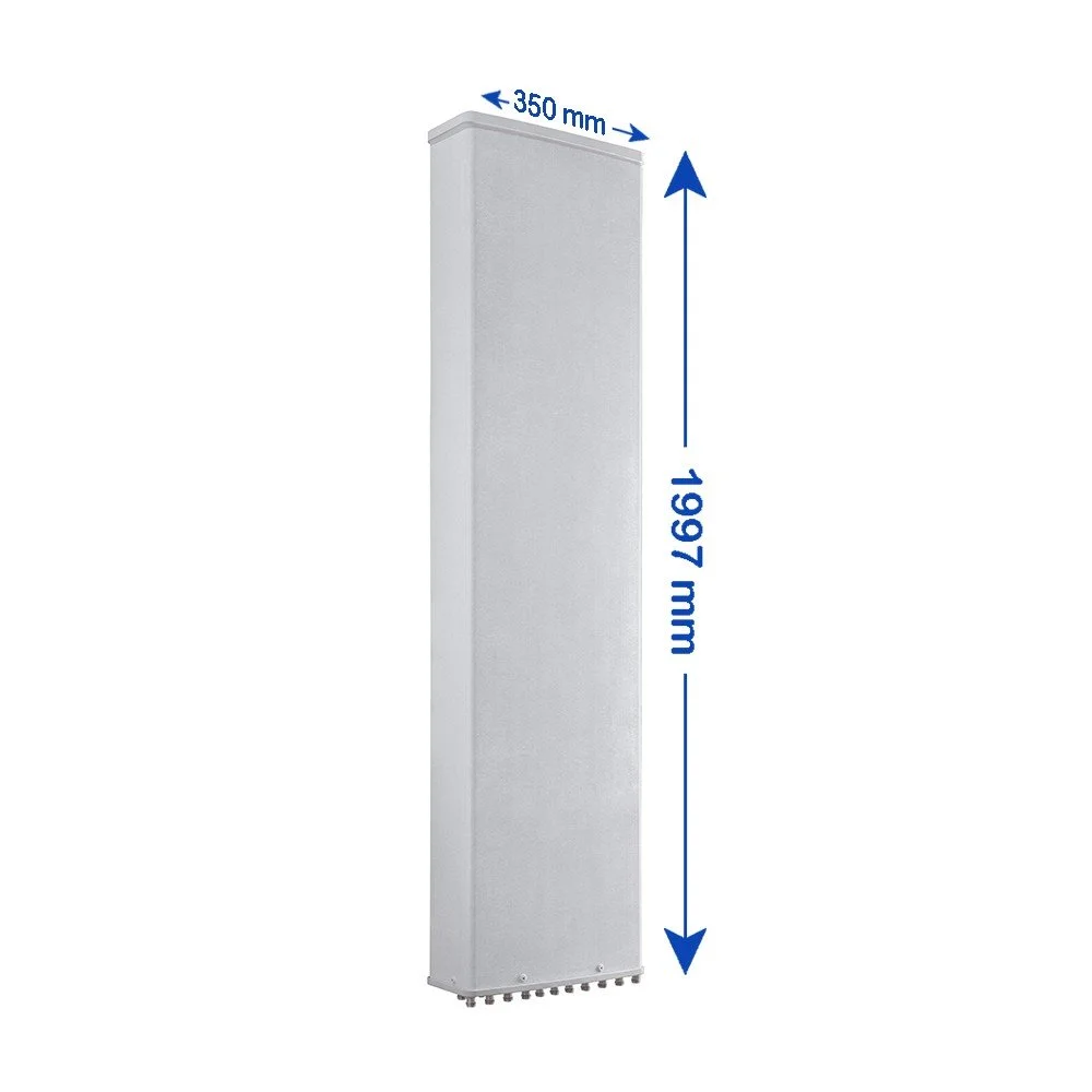 Image 3 of 6
 Image 4 of 6
 Image 5 of 6
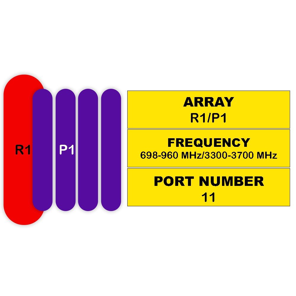 Image 6 of 6
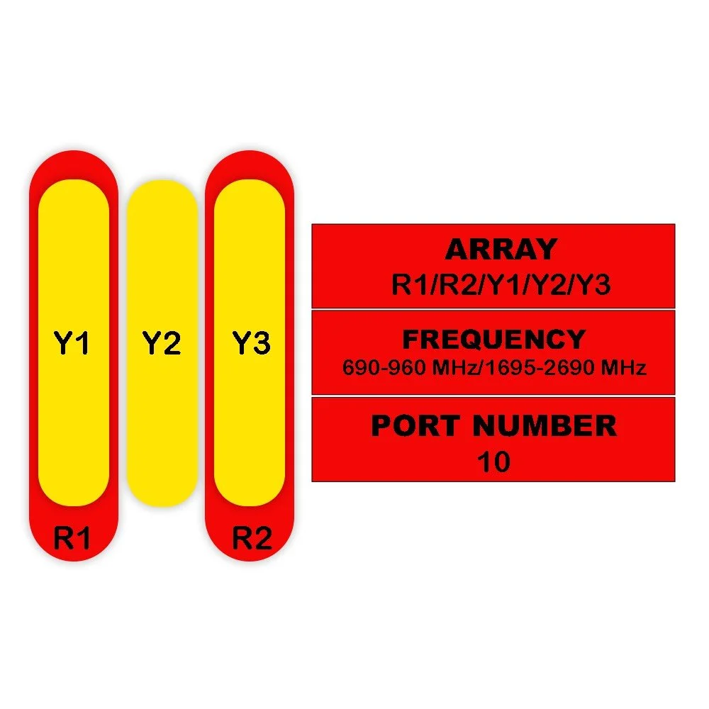
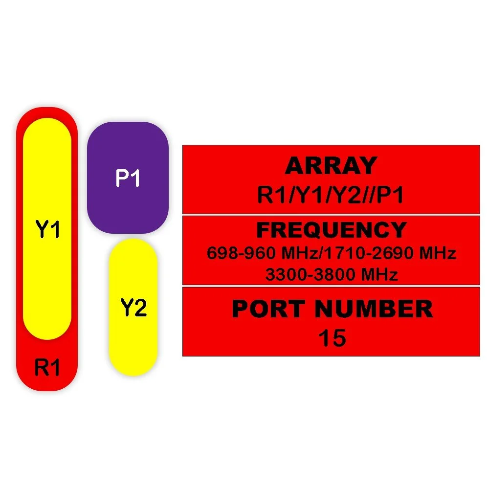
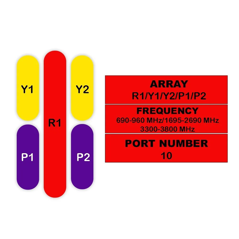
| Electrical Specifications | |||||
|---|---|---|---|---|---|
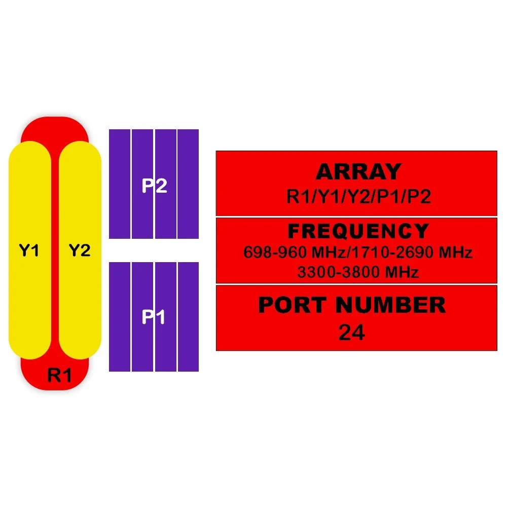
| Parameter | Sub Parameter | Unit | 698-806 | 790-894 | 880-960 |
| Frequency Range | MHz | 698-806 | 790-894 | 880-960 | |
| Polarization | --- | ±45° | |||
| Gain | at Mid Tilt | dBi | 14.8 | 15.4 | 15.8 |
| Over All Tilts | dBi | 14.7 ± 0.5 | 15.3 ± 0.5 | 15.7 ± 0.5 | |
| Horizontal Beamwidth | degree | 69 ± 5 | 66 ± 5 | 63 ± 5 | |
| Vertical Beamwidth | degree | 10.8 ± 1.0 | 9.8 ± 1.0 | 9.0 ± 0.9 | |
| Electrical Downtilt, Continuously Adjustable | degree | 2 – 12 | |||
| First Upper Side Lobe Suppression | dB | >16 | >16 | >16 | |
| Front-To-Back Ratio, ±30° | dB | >23 | >24 | >25 | |
| Isolation | Cross-Polar | dB | >25 | ||
| Interband | dB | >25 | |||
| Impedance | Ohm | 50 | |||
| VSWR | --- | <1.5 | |||
| Return Loss | dB | >14 | |||
| Lightning Protection | --- | DC Ground | |||
| Maximum Average Input Power per Port, at 50°C Ambient Temperature | Watts | 250 | |||
| TDD LTE Electrical Specifications (P1) | ||||
|---|---|---|---|---|
| Parameter | Sub Parameter | Unit | 3300-3600 | 3600-3700 |
| Frequency Range | MHz | 3300-3600 | 3600-3700 | |
| Polarization | --- | ±45° | ||
| Electrical Downtilt | Continuously Adjustable | degree | 2-12 | |
| Single Column Beam | ||||
| Gain | dBi | 15.1 ± 1 | 15.5 ± 1 | |
| Horizontal Beamwidth | degree | 75 ± 15 | 70 ± 15 | |
| Vertical Beamwidth (3 dB) | degree | 6.6 ± 0.8 | 6.0 ± 0.6 | |
| Cross-Polar Discrimination (Boresight) | dB | ≥ 15 | ≥ 15 | |
| Cross-Polar Discrimination (Sector) | dB | ≥ 8 | ≥ 8 | |
| First Upper Side Lobe Suppression | dB | ≥ 15 | ≥ 15 | |
| Front-To-Back Ratio | dB | ≥ 23 | ≥ 23 | |
| 65° Broadcast Beam | ||||
| Gain | dB | 16.5 | 17.0 | |
| Horizontal Beamwidth (10 dB) | degree | 115 | 108 | |
| First Upper Side Lobe Suppression | dB | ≥ 15 | ≥ 15 | |
| Front-To-Back Ratio | dB | ≥ 25 | ≥ 25 | |
| Service Beam | ||||
| 0° Direct Beam Gain | dBi | 20.5 | 21 | |
| 0° Direct Beam Horizontal 3 dB Beamwidth | degree | 26 | 24 | |
| 0° Direct Beam Cross-Polar Ratio | dB | ≥ 16 | ≥ 17 | |
| 0° Direct Beam Front-To-Back Ratio | dB | ≥ 27 | ≥ 28 | |
| 0° Direct Beam Horizontal Sidelobe | dB | 12 | 12 | |
| ±30° Direction Beam Gain | dBi | 19.0 | 19.5 | |
| ±30° Direction Beam Horizontal 3 dB Beamwidth | degree | 28 | 25 | |
| ±30° Direction Beam Front-To-Back Ratio | dB | ≥ 24 | ≥ 25 | |
| Soft Split Multi-Beam | ||||
| Gain | dBi | 19.3 | 19.8 | |
| Horizontal Beamwidth (3 dB) | degree | 31 | 29 | |
| Front-To-Back Ratio | dB | ≥ 25 | ≥ 25 | |
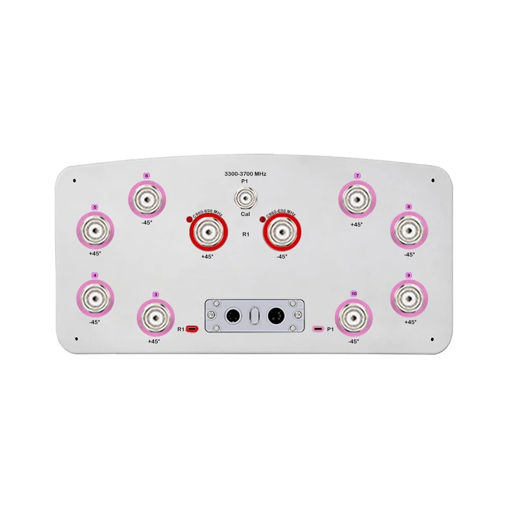
| Calibration and Electrical Parameter | ||||
| Coupling Factor Between Calibration And Each Antenna Port | dB | -26 ± 2 | ||
| Maximum Amplitude Tolerance | dB | ≤ 1.0 | ||
| Maximum Phase Tolerance | degree | ≤ 9 | ||
| Ports VSWR | --- | < 1.5 | ||
| Average Power Capacity | W | 25 | ||
| Co-Polar Isolation Between Ports | dB | ≥ 23 | ||
| Inter-band Isolation | dB | ≥ 23 | ||
| Impedance | Ohms | 50 | ||
| Lightning Protection | --- | DC Ground | ||
| 5G Electrical Specifications (P1) | ||||
|---|---|---|---|---|
| Parameter | Sub Parameter | Unit | 3300-3600 | 3600-3700 |
| Frequency Range | MHz | 3300-3600 | 3600-3700 | |
| Single Column Beam | ||||
| Gain | dBi | 15.1 ± 1 | 15.5 ± 1 | |
| Horizontal Beamwidth | degree | 75 ± 15 | 70 ± 15 | |
| Vertical Beamwidth (3 dB) | degree | 6.6 ± 0.8 | 6.0 ± 0.6 | |
| Cross-Polar Discrimination (Boresight) | dB | ≥ 15 | ≥ 15 | |
| Cross-Polar Discrimination (Sector) | dB | ≥ 8 | ≥ 8 | |
| First Upper Side Lobe Suppression | dB | ≥ 15 | ≥ 15 | |
| Broadcast Beam (±13°, ±43° Service Beam) | ||||
| Gain | dB | 20.0 | 20.5 | |
| Horizontal Beamwidth (10 dB) | degree | 120 | 115 | |
| First Upper Side Lobe Suppression | dB | ≥ 15 | ≥ 15 | |
| Front-To-Back Ratio | dB | ≥ 25 | ≥ 25 | |
| Service Beam | ||||
| 0° Direct Beam Gain | dBi | 20.5 | 21 | |
| 0° Direct Beam Horizontal 3 dB Beamwidth | degree | 26 | 24 | |
| 0° Direct Beam Cross-Polar Ratio at Beampeak | dB | ≥ 16 | ≥ 17 | |
| 0° Direct Beam Front-To-Back Ratio | dB | ≥ 27 | ≥ 28 | |
| 0° Direct Beam Horizontal Sidelobe | dB | 12 | 12 | |
| Mechanical Specifications | ||||
|---|---|---|---|---|
| Parameter | Sub Parameter | Unit | Value | Notes |
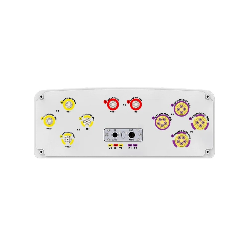
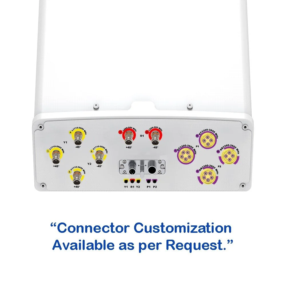
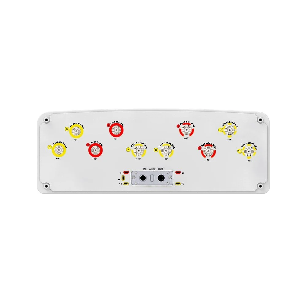
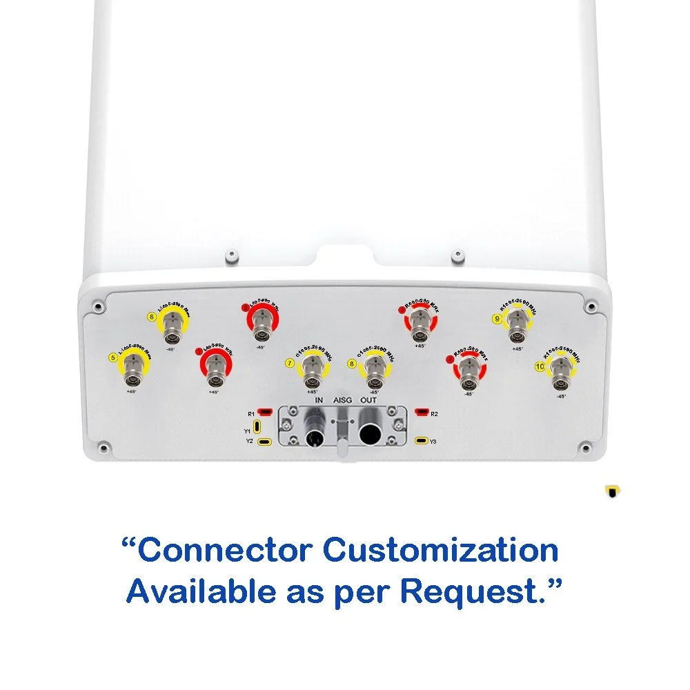
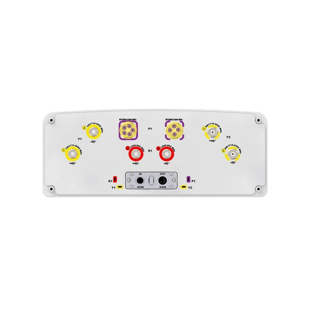
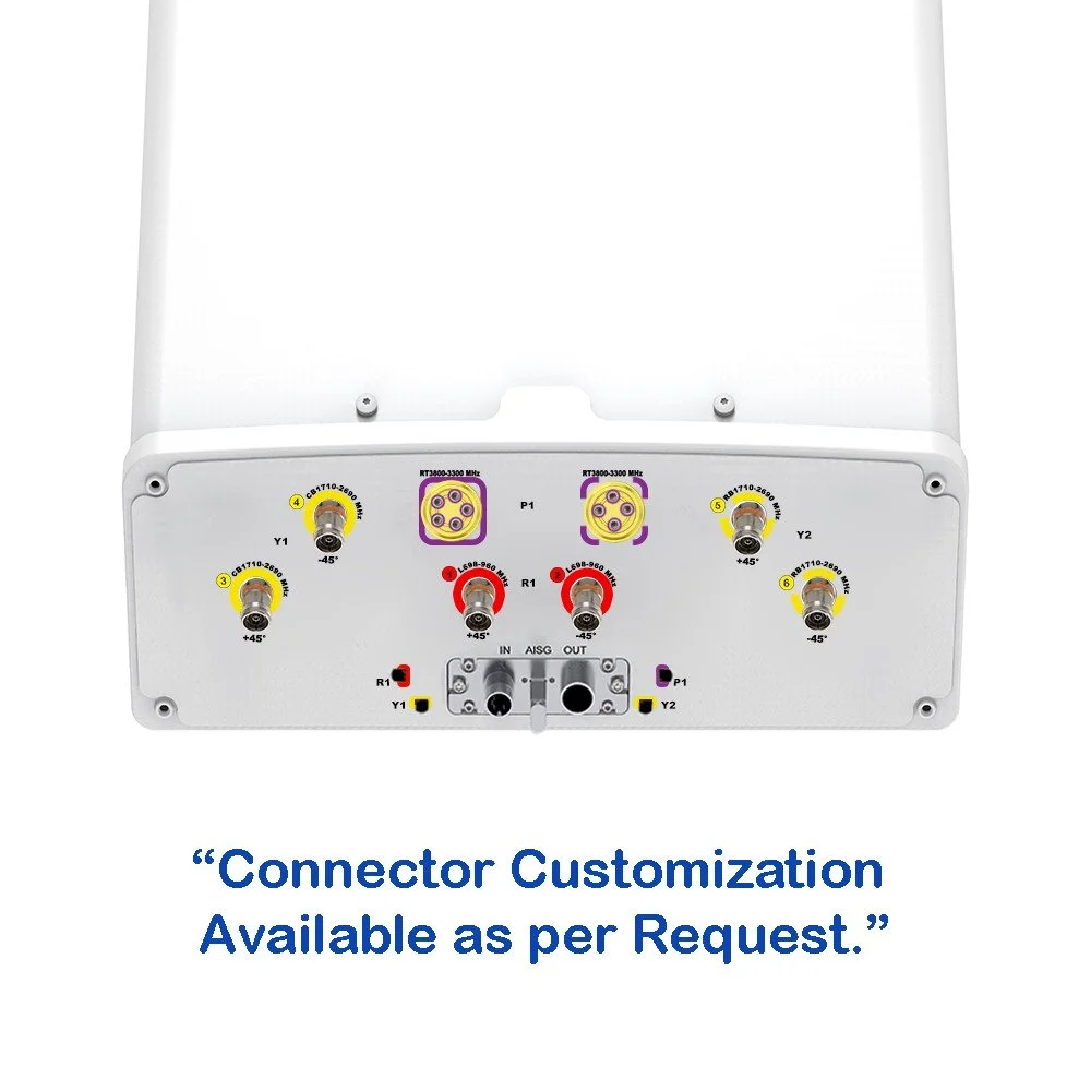
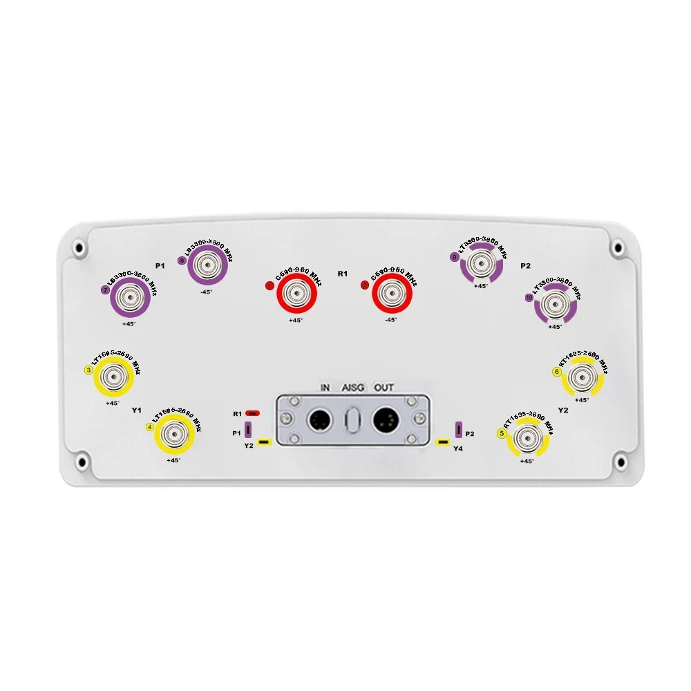
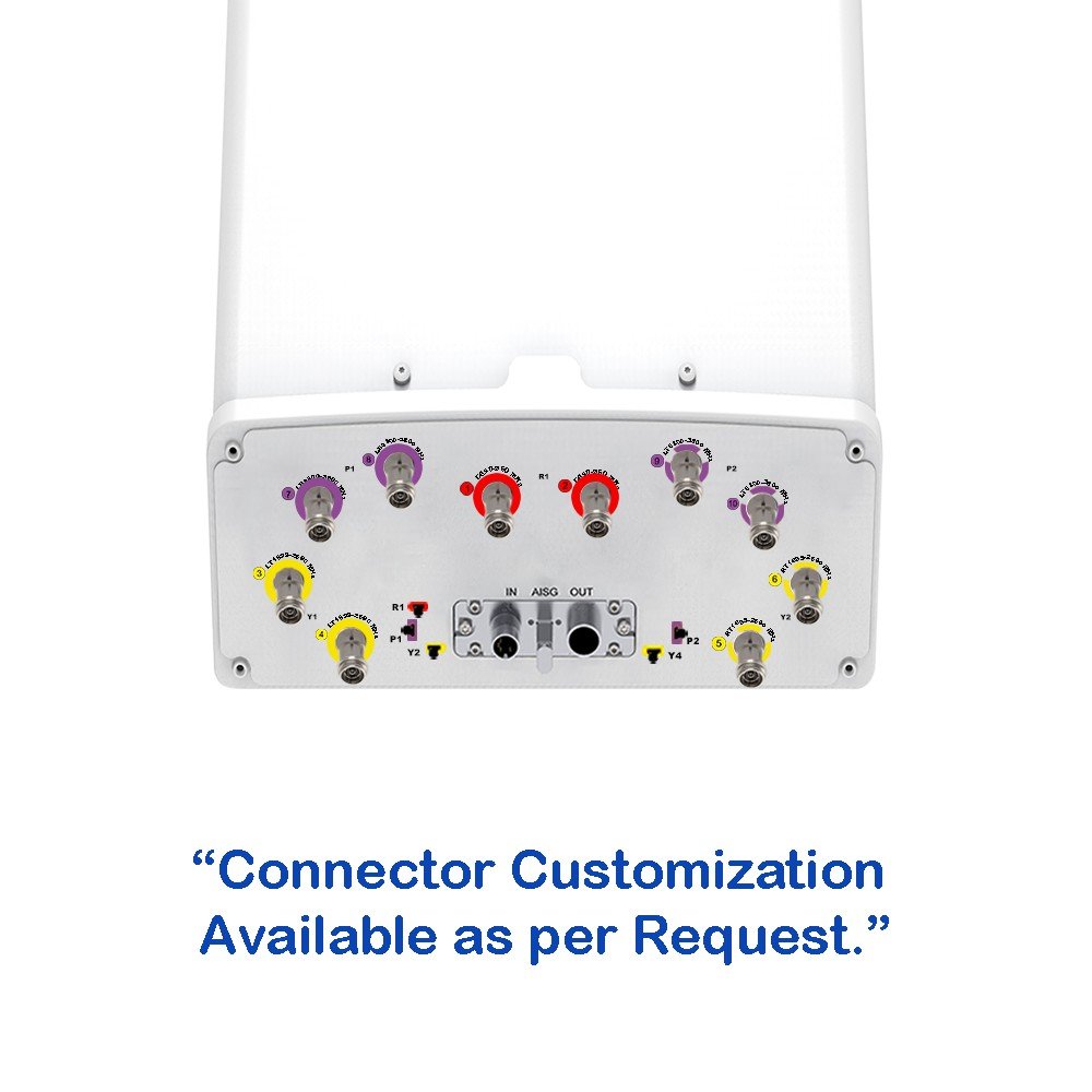
| Connector Type | --- | (10x) 4.3/10 Female | (1x) 4.3/10 Female Calibration Port | |
| Connector Position | --- | Bottom | ||
| Electrical Tilt Control | --- |
FDD: Integrated RET, Each Band Individually Adjustable TDD: Integrated RET, Single Internal RET Control for All Four Antenna Arrays |
||
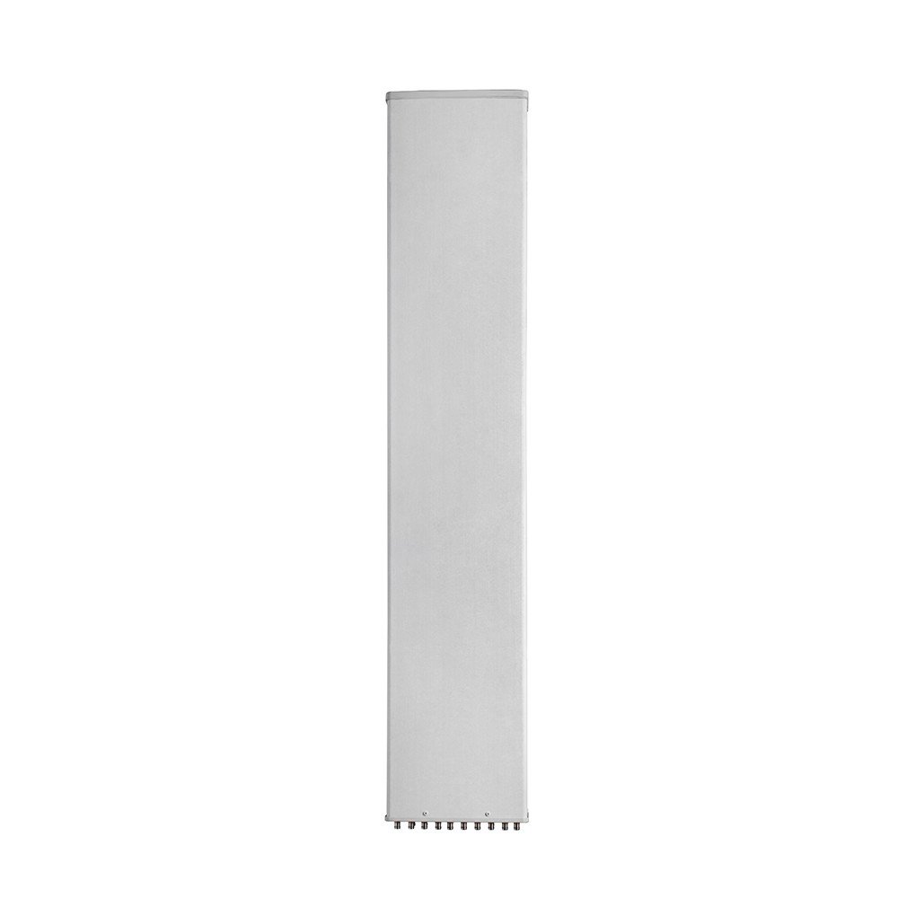
| Radome Material | --- | UPVC | ||
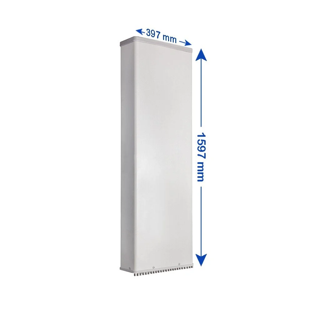
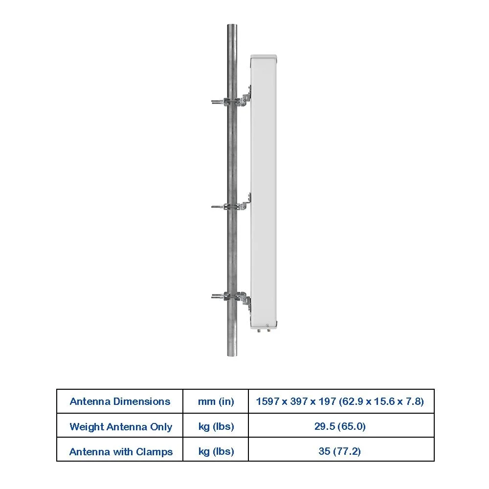
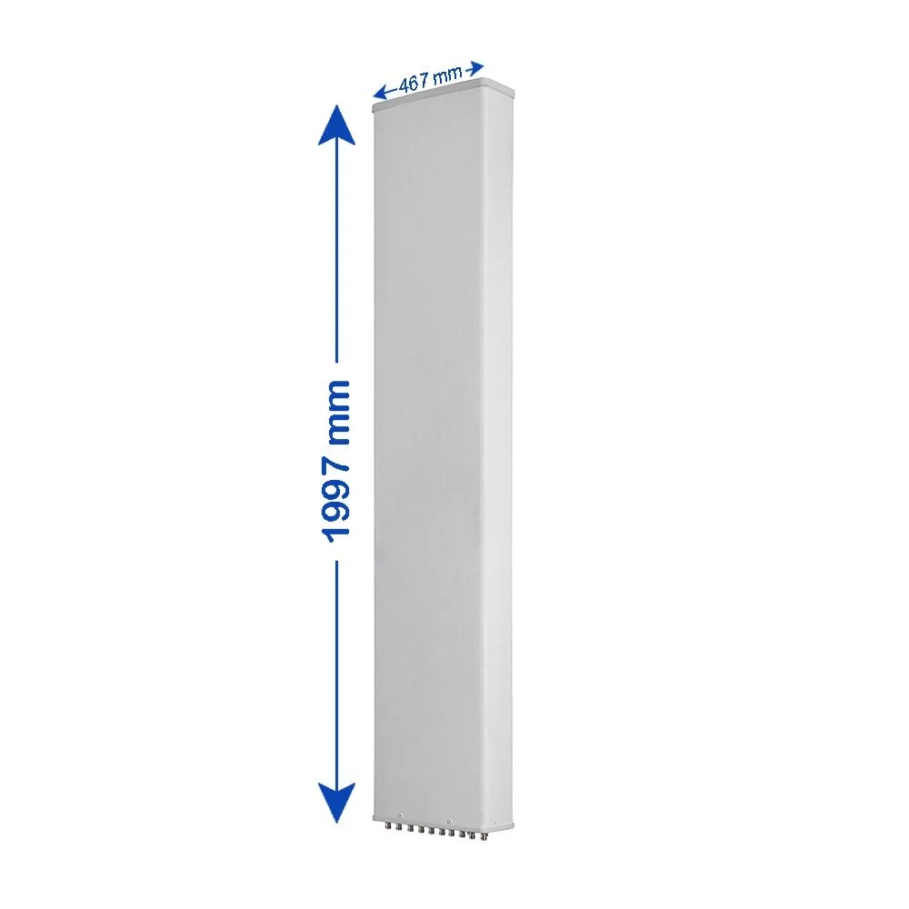
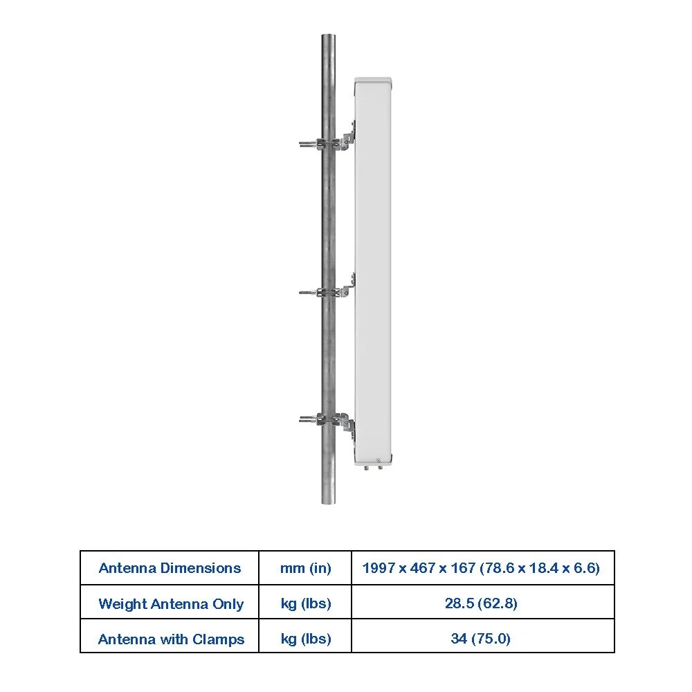
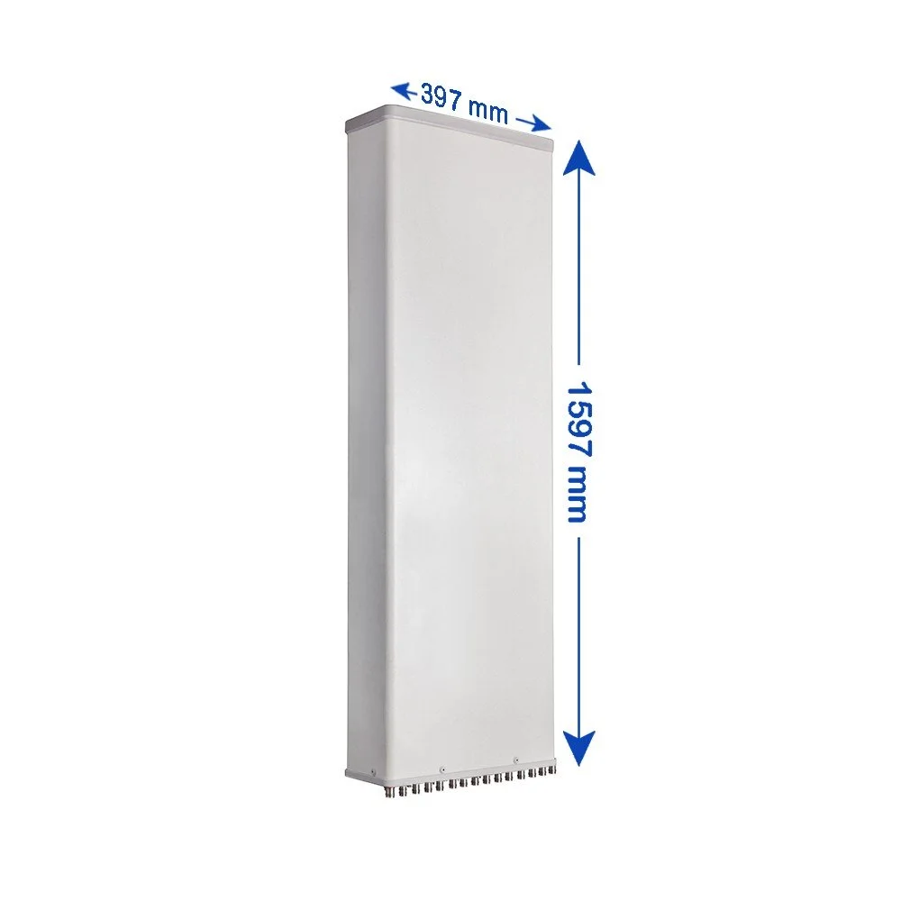
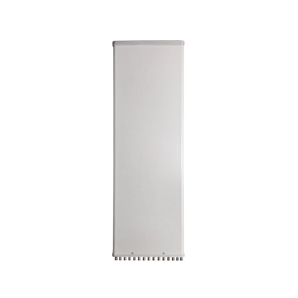
| Antenna Dimensions (H × W × D) | mm (in) | 1997 × 350 × 178 (78.6 × 13.8 × 7.0) | ||
| Antenna Weight | Antenna Only | kg (lbs) | 24 (52.9) | |
| With Clamps | kg (lbs) | 28 (61.7) | ||
| Maximum Wind Speed | km/h (mph) | 200 (124.3) | ||
| Wind Load at 150 km/h | Frontal | N (lbf) | 645 (145.0) | |
| Rear | N (lbf) | 720 (161.9) | ||
| Lateral | N (lbf) | 435 (97.8) | ||
| Operating Temperature | °C (°F) | -40 to +60 (-40 to +140) | ||