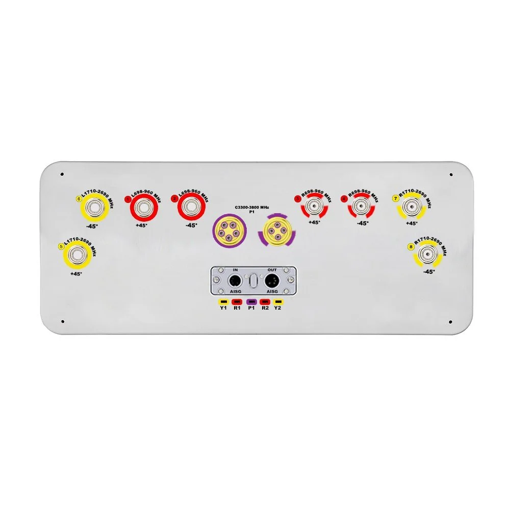
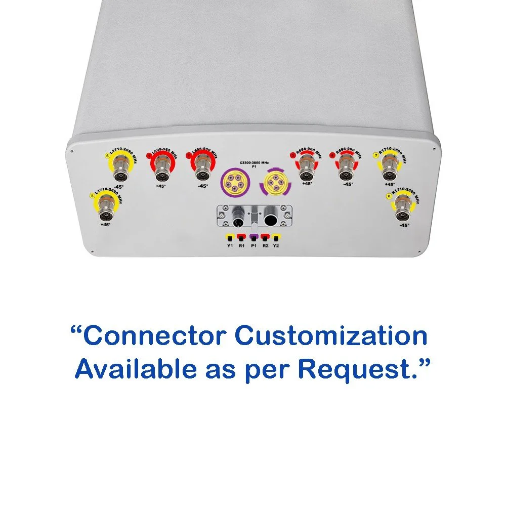
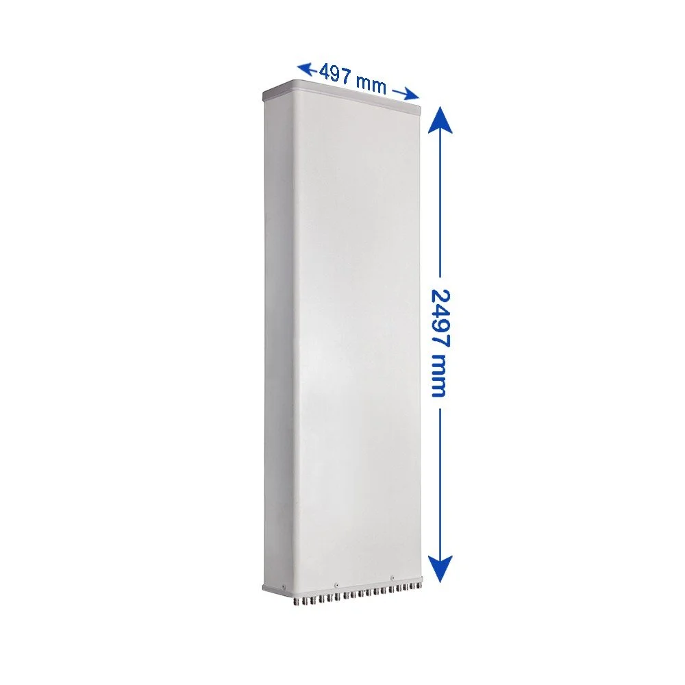
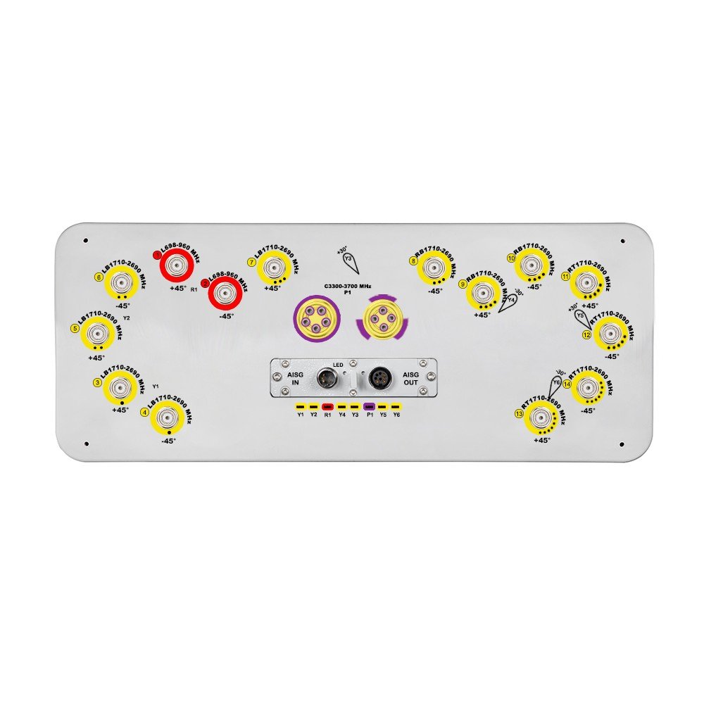
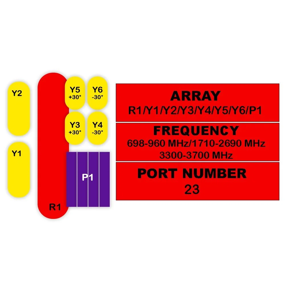
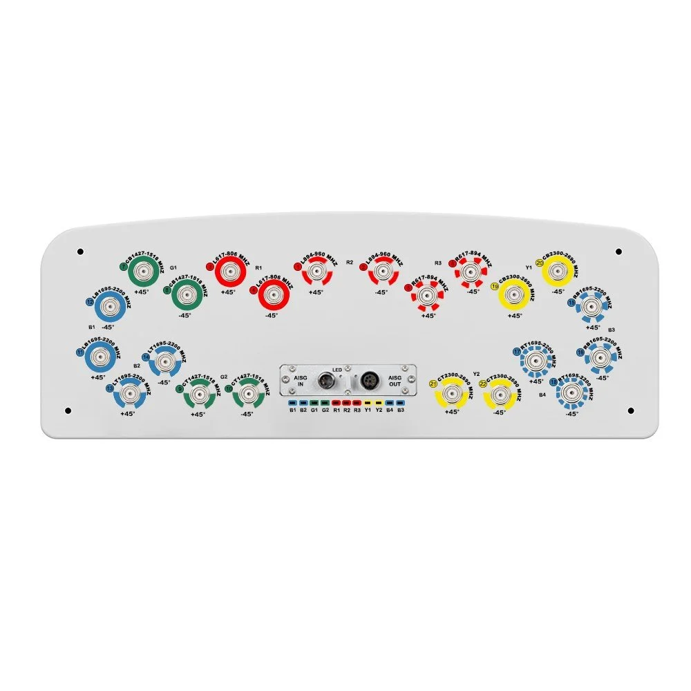
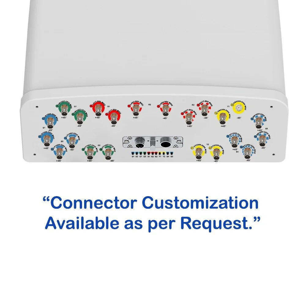
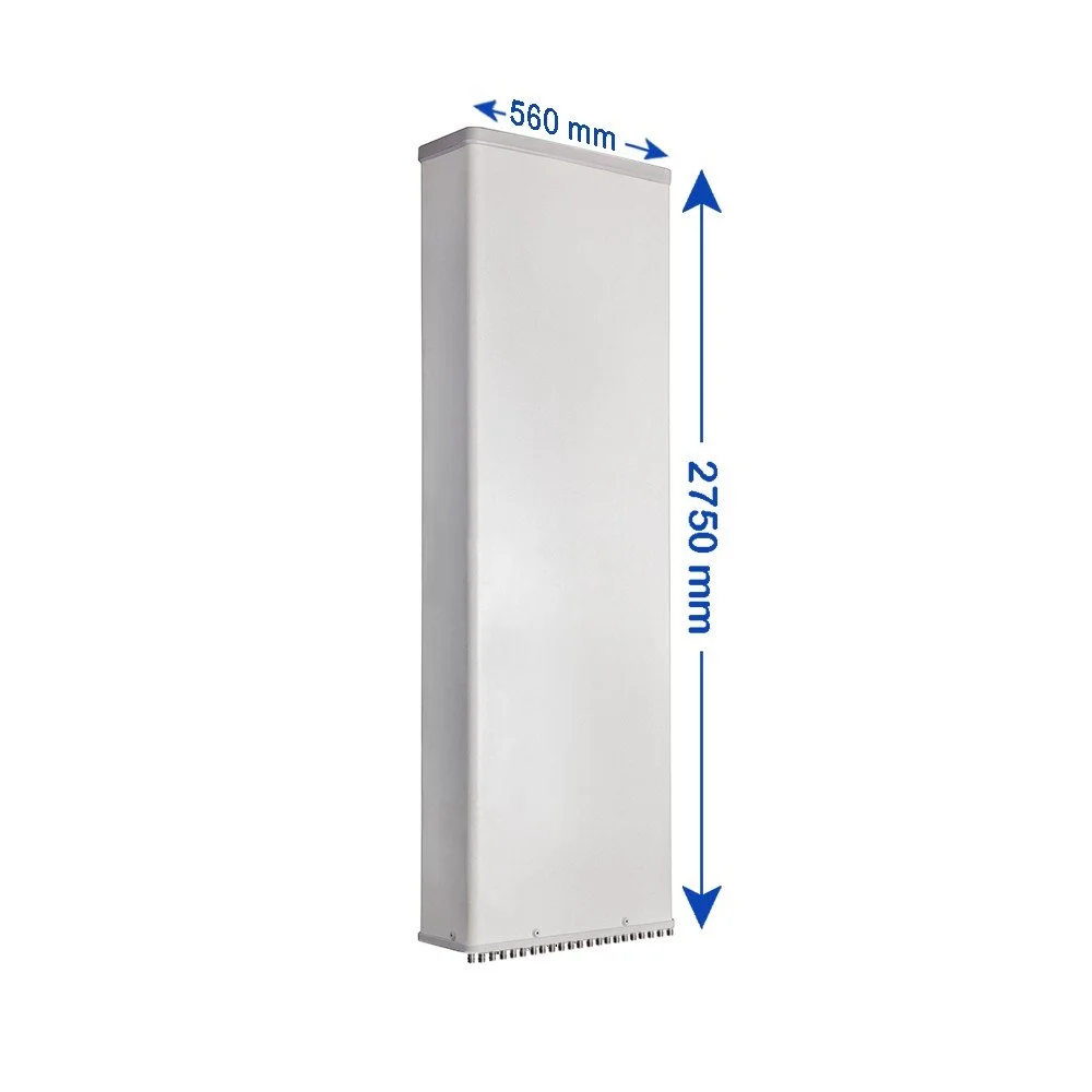
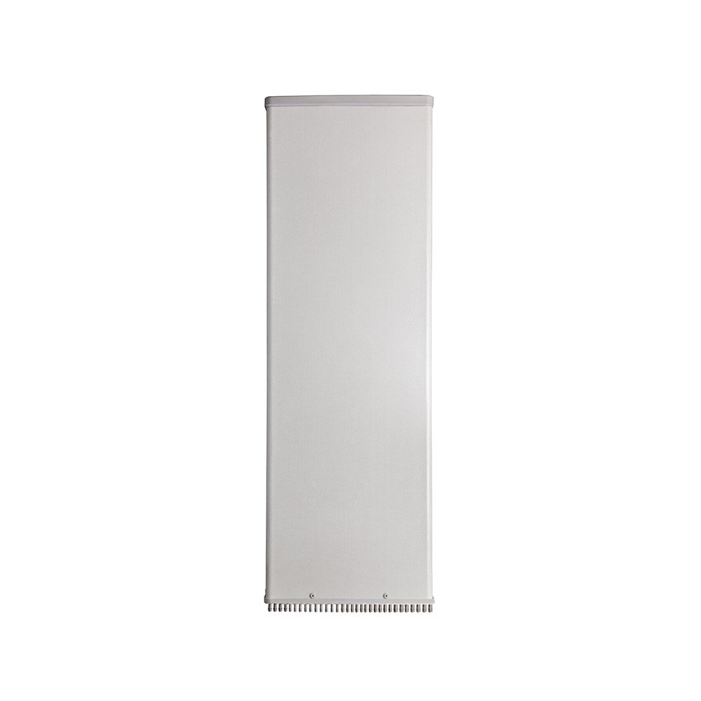
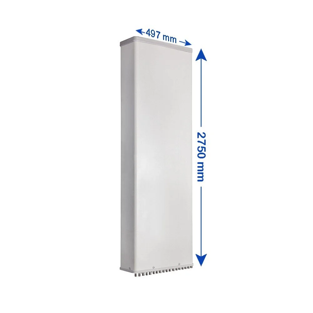
10-Port Panel Sector Antenna (698–2690 MHz)
Overview :
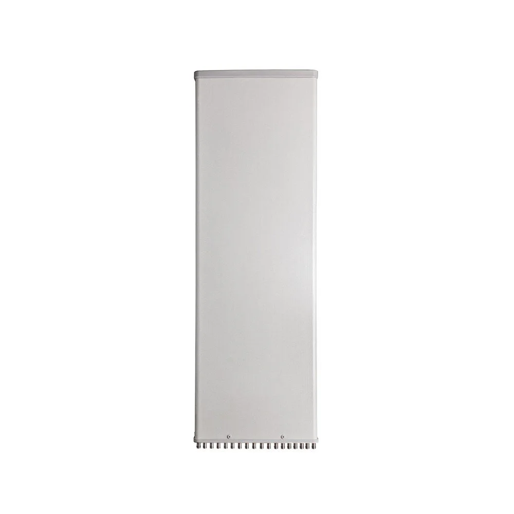
An advanced multi-port panel sector antenna engineered for modern multi-operator and multi-technology deployments across 698–2690 MHz. Delivers high isolation between ports, consistent sector coverage, and durable environmental protection for rooftop, tower, and wall-mount installations. Ideal for shared-cell sites, neutral host systems, small cell aggregation, and capacity-focused macro sectors.
Key Features :
Frequency range: 698–2690 MHz (covers low-band, mid-band LTE and early 5G NR bands within this range)
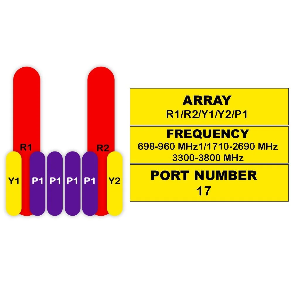
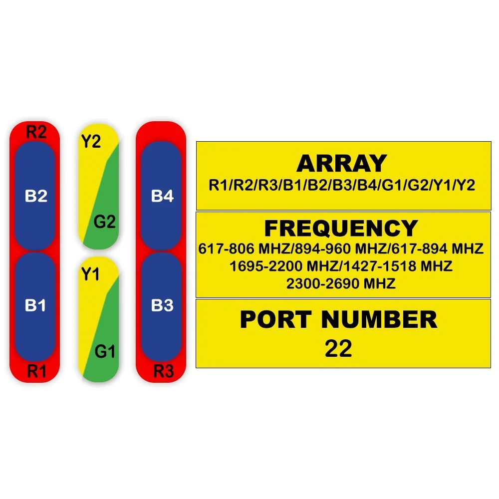
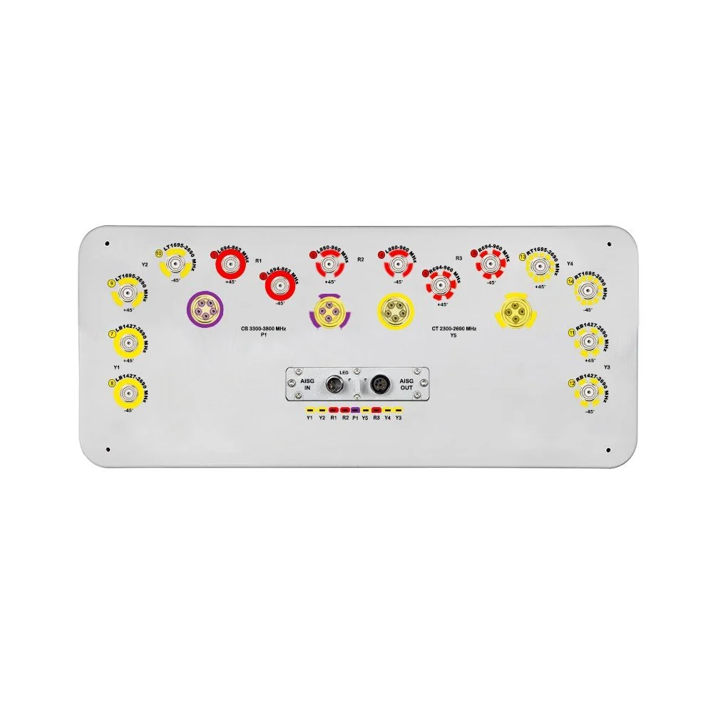
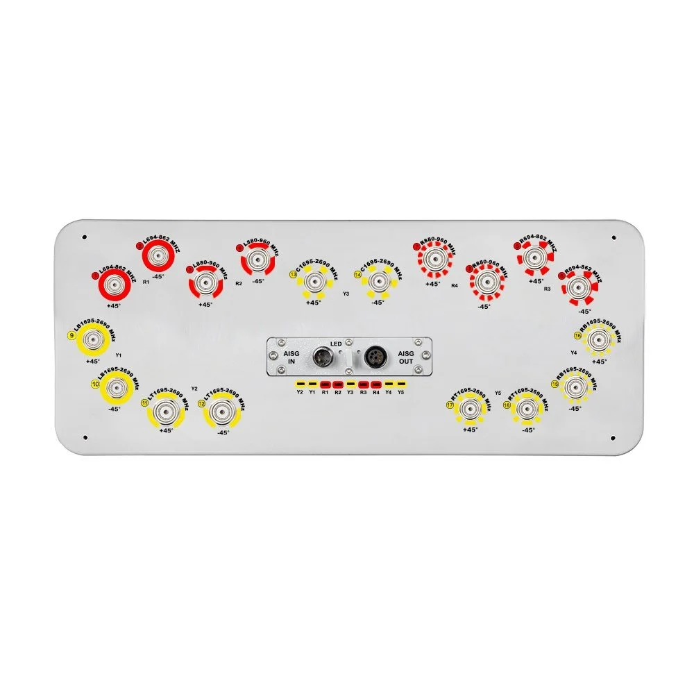
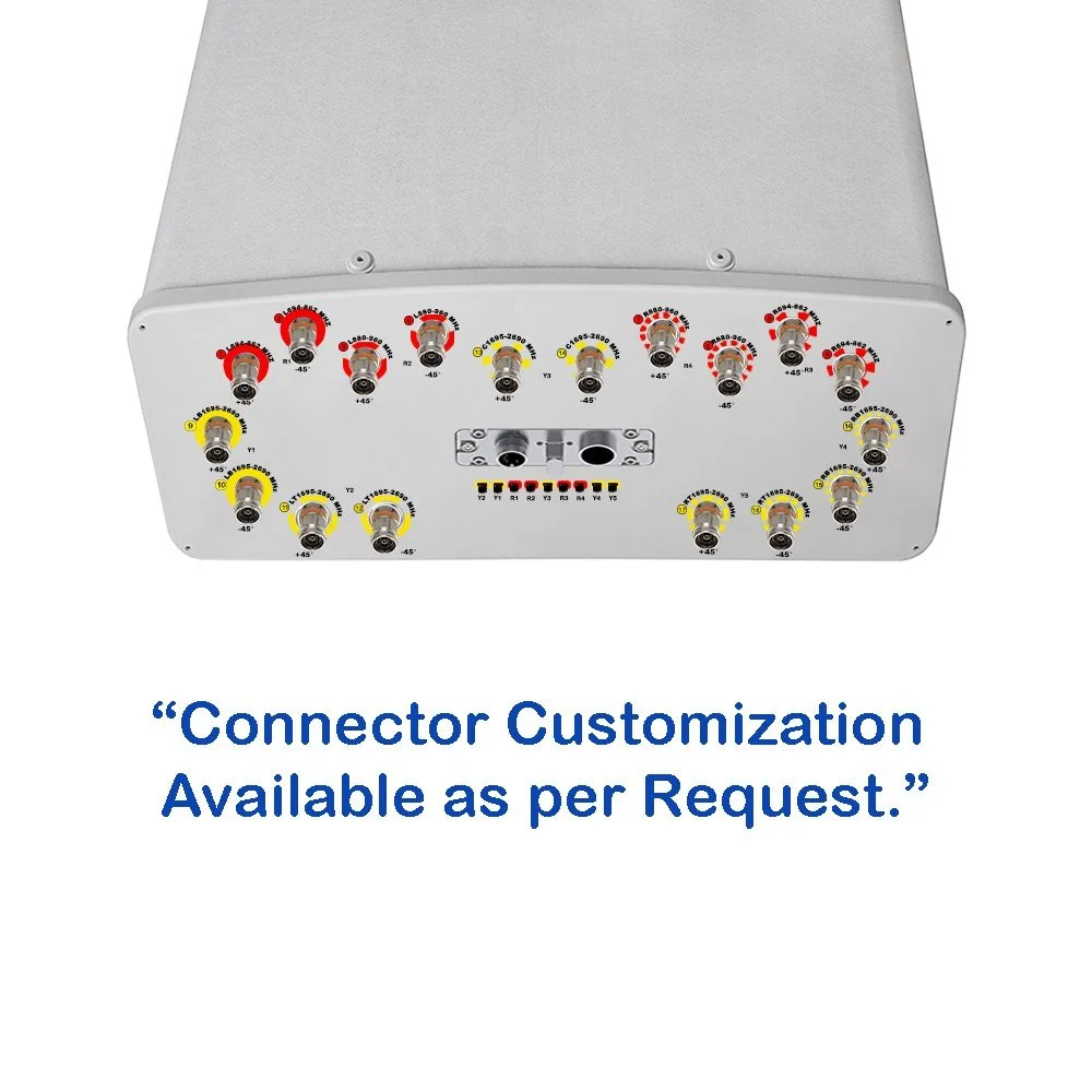
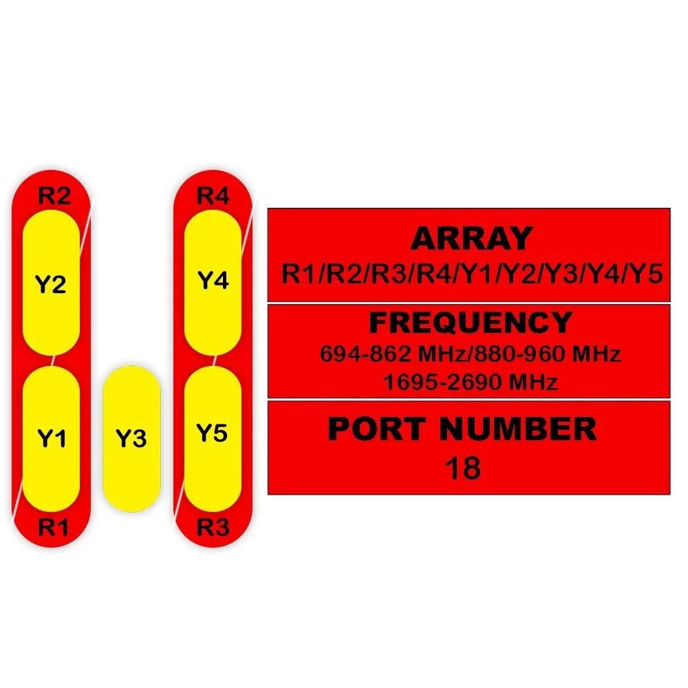
10 RF ports supporting multiple operators, MIMO layers, or separate carrier groups
Sector beamwidth: 65° typical (configurable variants for 60°/90° available on request)
High port-to-port isolation to minimize inter-operator and inter-system interference
Low return loss: ≤ -10 dB across the full band (typical ≤ -12 dB)
Gain: 7–10 dBi across band (band-dependent, see detailed specs)
VSWR: ≤ 2.0:1 typical
Dual-polarized elements with phase and amplitude alignment for consistent pattern shape
Integrated downtilt options: mechanical and optional electrical tilt module support
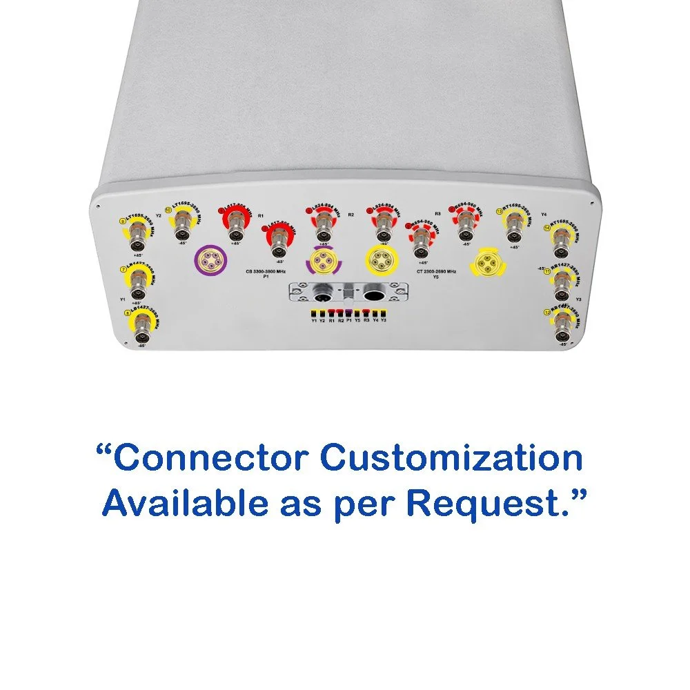
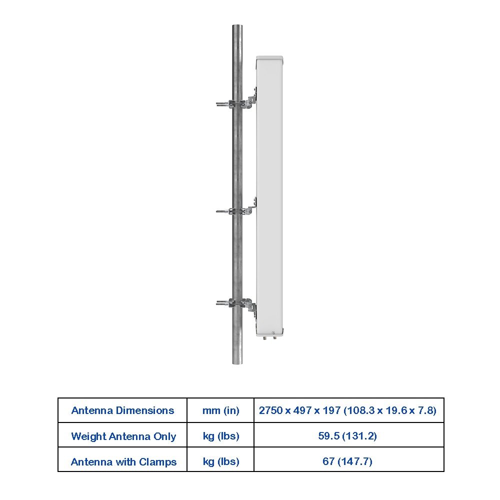
Robust RF connectors with weatherproof radomes and factory-sealed cable harness options
IP65/66 environmental rating and UV-stable radome material for long outdoor life
Operating temperature: -40 °C to +65 °C
10-Port Panel Sector Antenna (698–2690 MHz)
Overview :
An advanced multi-port panel sector antenna engineered for modern multi-operator and multi-technology deployments across 698–2690 MHz. Delivers high isolation between ports, consistent sector coverage, and durable environmental protection for rooftop, tower, and wall-mount installations. Ideal for shared-cell sites, neutral host systems, small cell aggregation, and capacity-focused macro sectors.
Key Features :
Frequency range: 698–2690 MHz (covers low-band, mid-band LTE and early 5G NR bands within this range)
10 RF ports supporting multiple operators, MIMO layers, or separate carrier groups
Sector beamwidth: 65° typical (configurable variants for 60°/90° available on request)
High port-to-port isolation to minimize inter-operator and inter-system interference
Low return loss: ≤ -10 dB across the full band (typical ≤ -12 dB)
Gain: 7–10 dBi across band (band-dependent, see detailed specs)
VSWR: ≤ 2.0:1 typical
Dual-polarized elements with phase and amplitude alignment for consistent pattern shape
Integrated downtilt options: mechanical and optional electrical tilt module support
Robust RF connectors with weatherproof radomes and factory-sealed cable harness options
IP65/66 environmental rating and UV-stable radome material for long outdoor life
Operating temperature: -40 °C to +65 °C

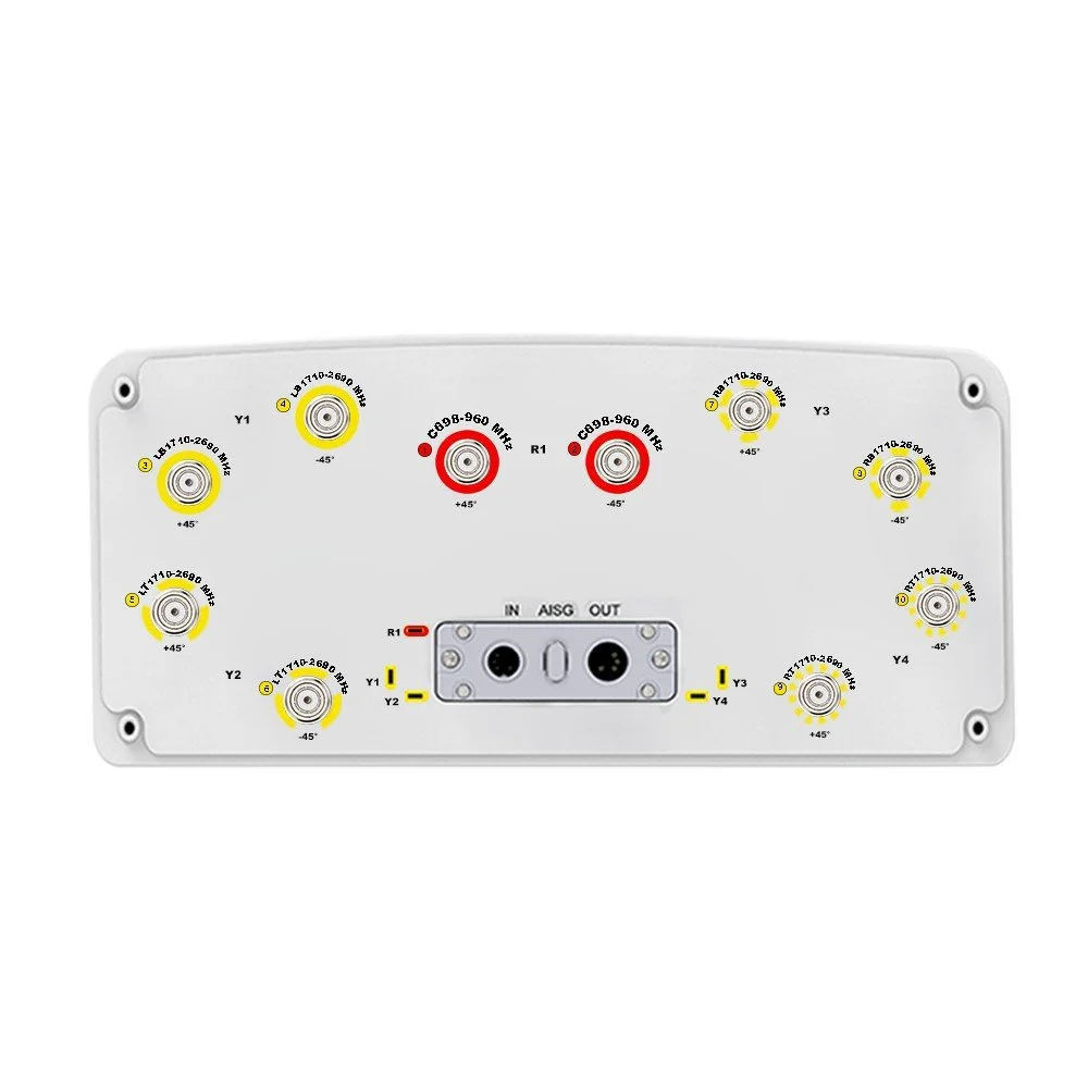 Image 1 of 6
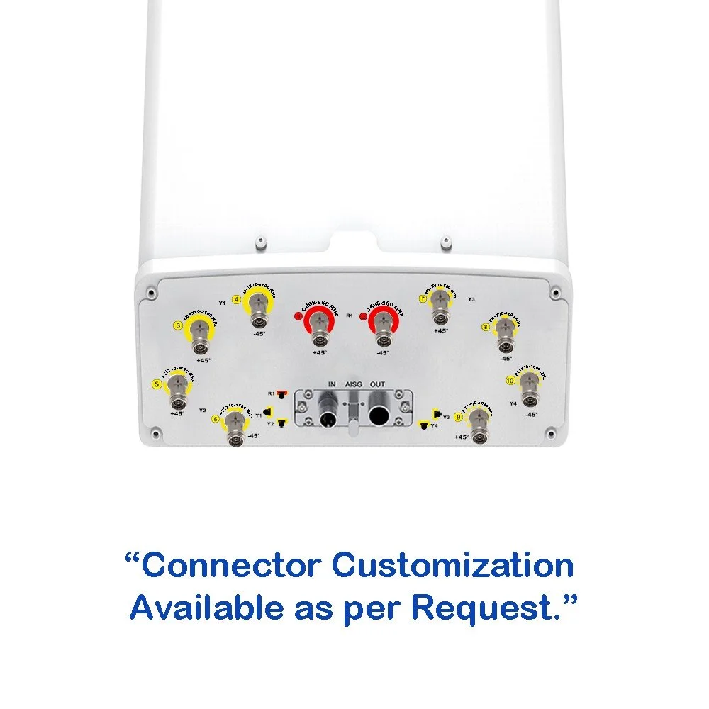 Image 2 of 6
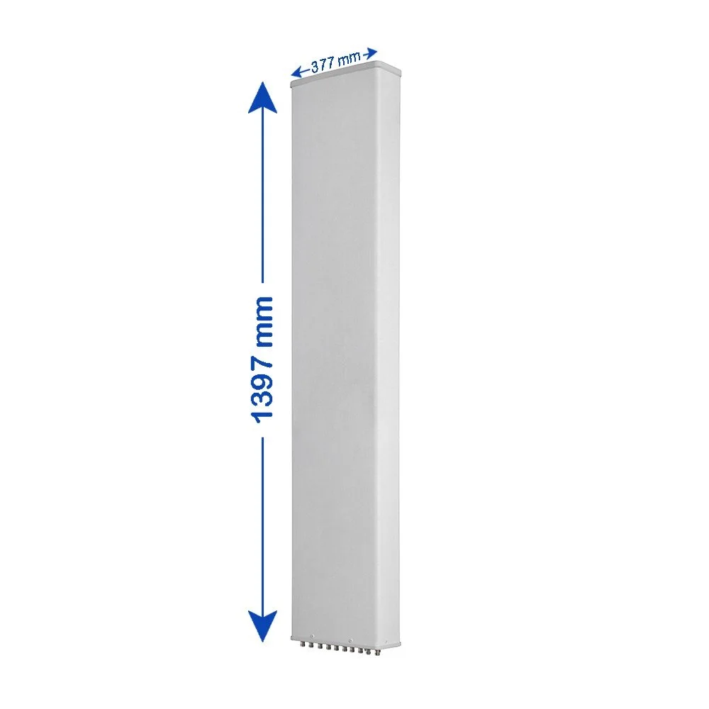 Image 3 of 6
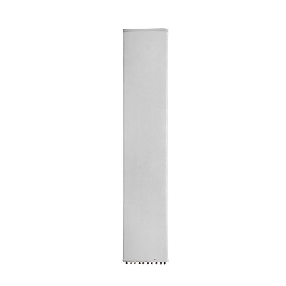 Image 4 of 6
 Image 5 of 6
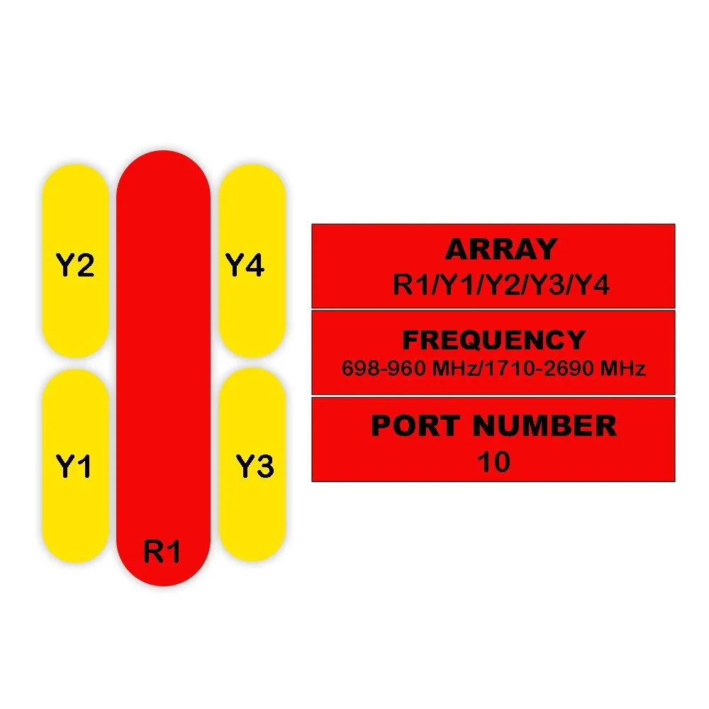 Image 6 of 6