10-Port Panel Sector Antenna (690–2690 MHz)
Overview :
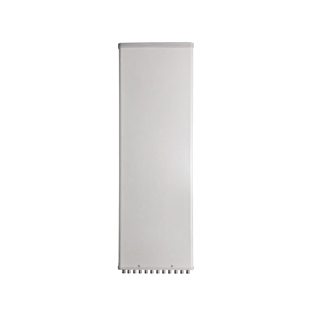
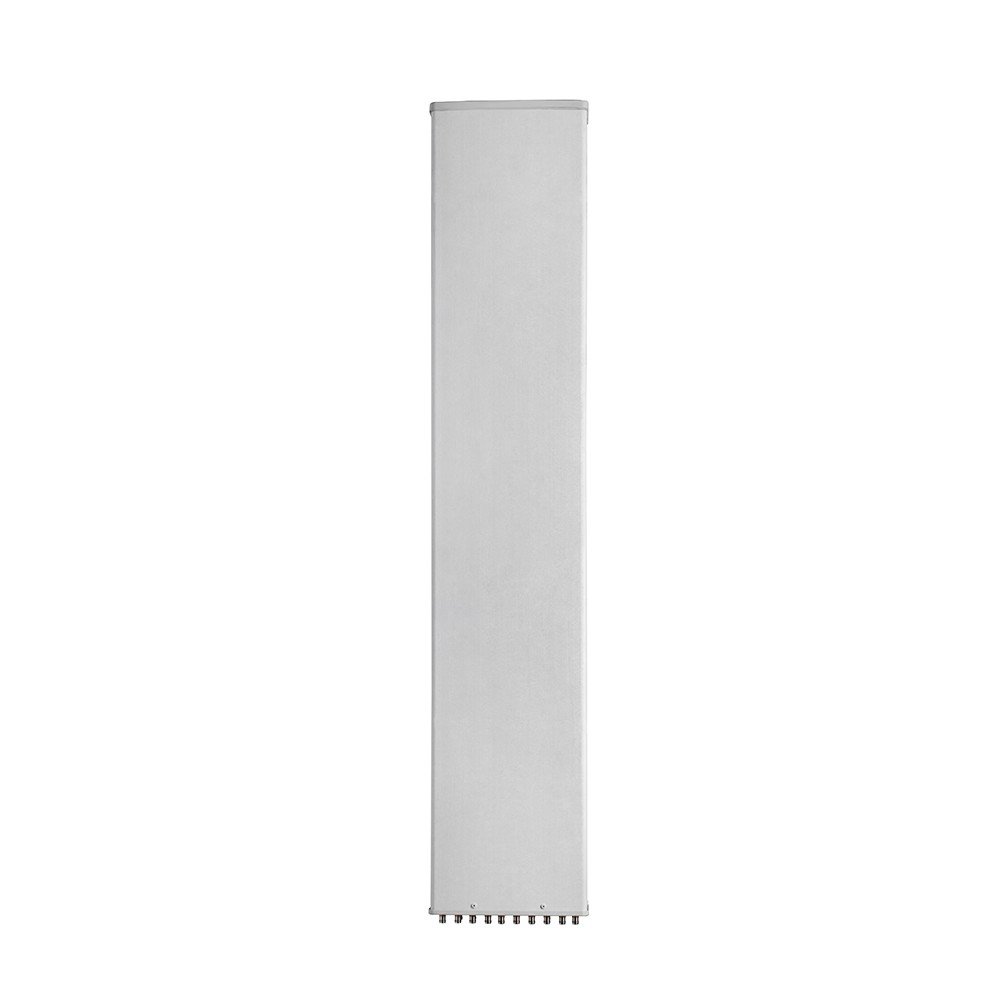
A high-performance 10-port panel sector antenna engineered for modern multi-operator and multi-band deployments. Covers 690–2690 MHz with industry-leading isolation between ports, compact form factor, and ruggedized housing for reliable outdoor installation. Ideal for dense urban sites, rooftop sectors, and shared tower environments where multiple carriers or technologies (2G/3G/4G/LTE/CBRS) must coexist on a single sector.
Key Features :
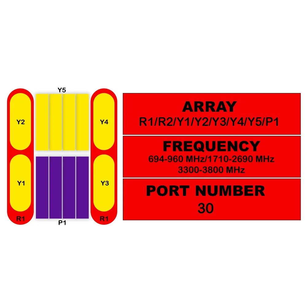
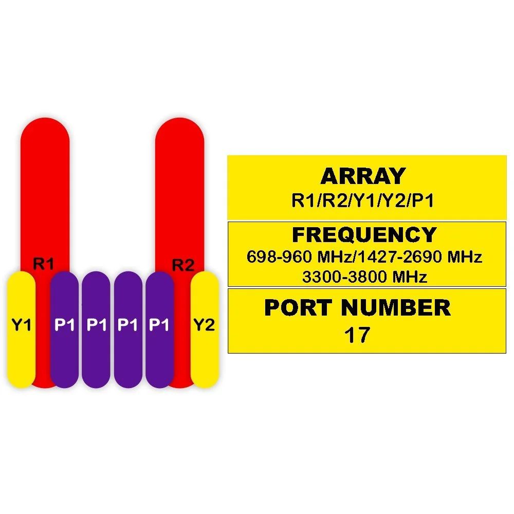
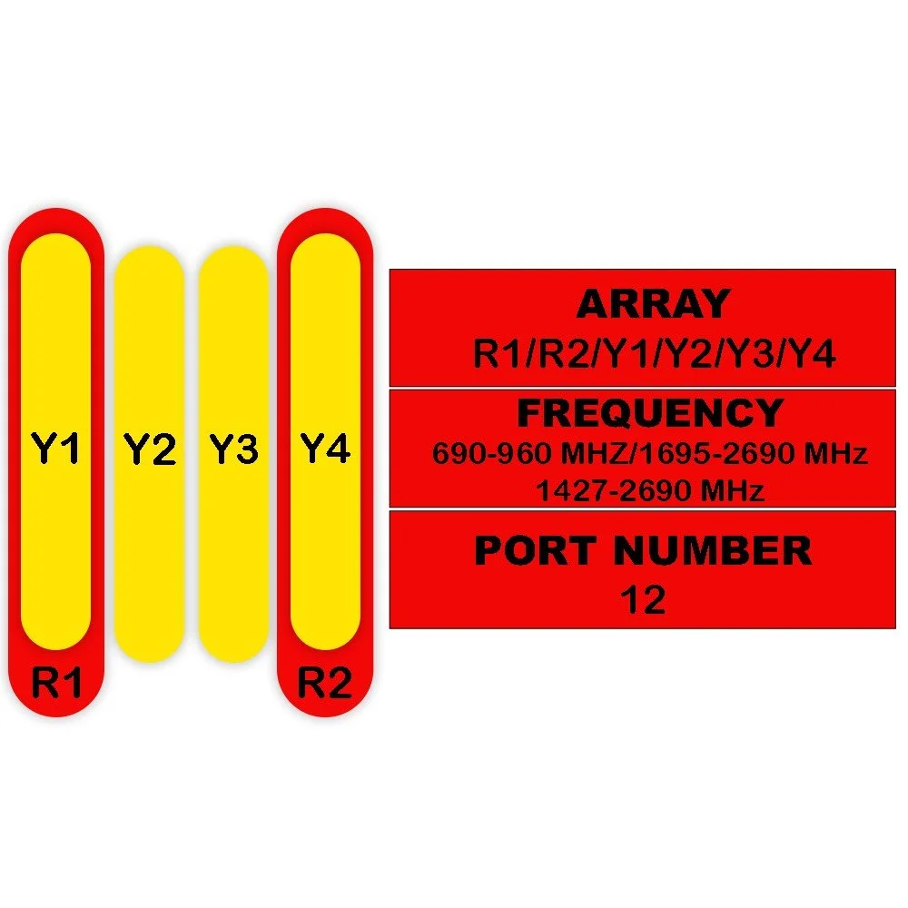
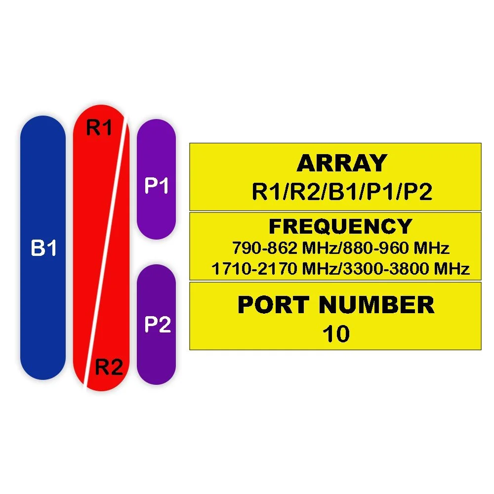
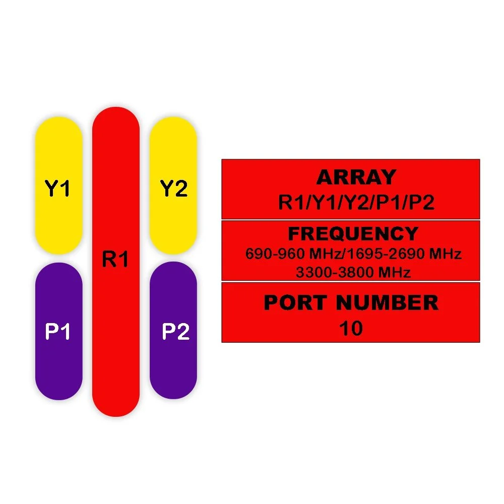
Frequency range: 690–2690 MHz continuous coverage for low-band and mid-band cellular and CBRS.
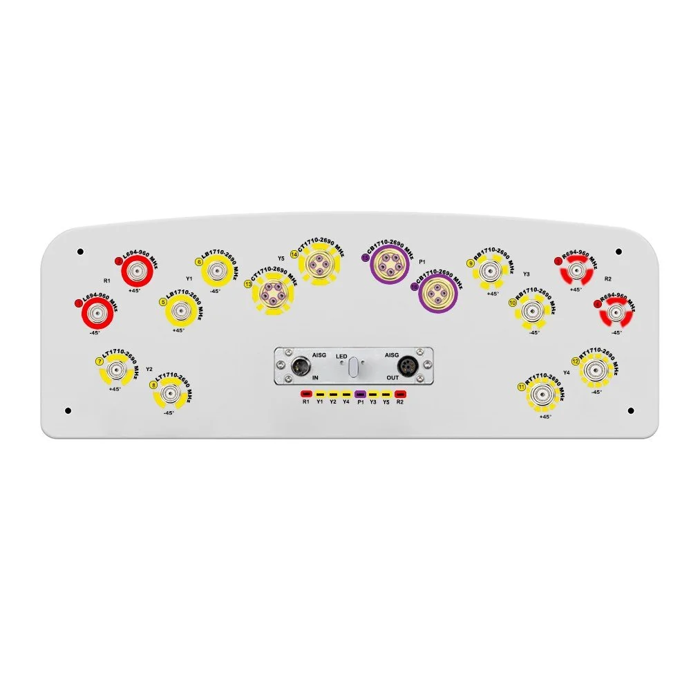
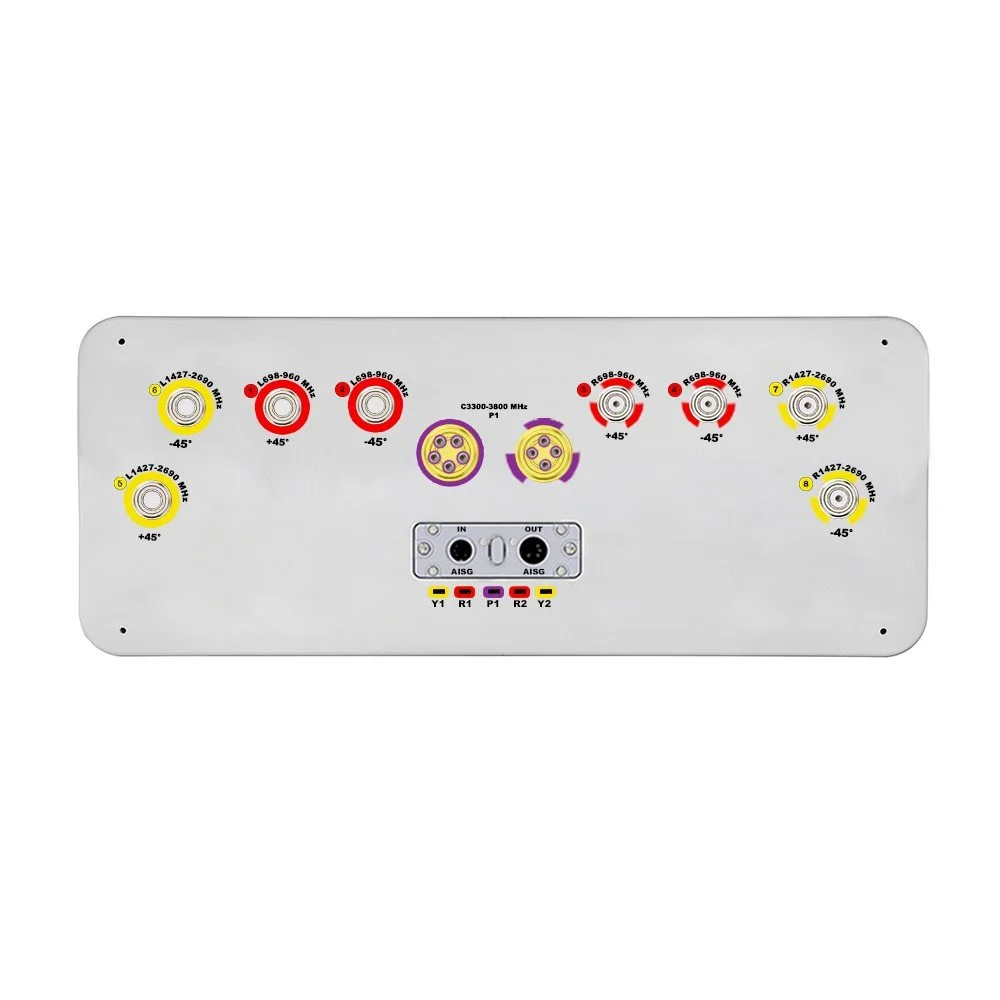
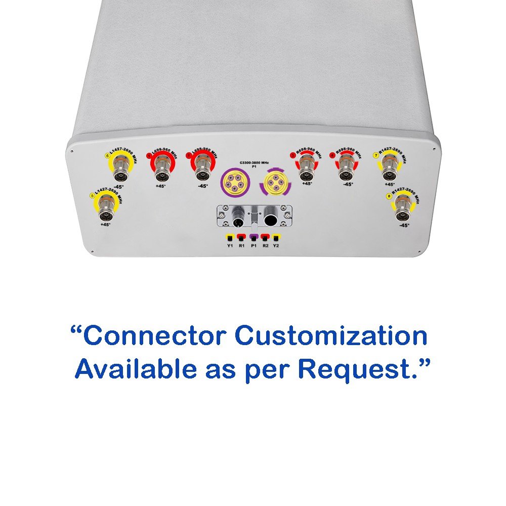
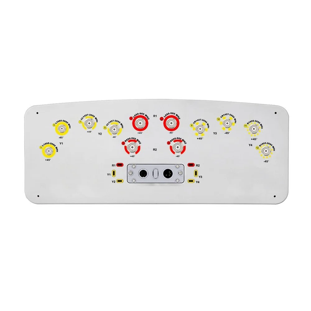
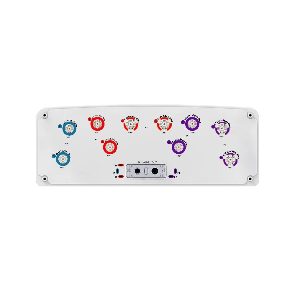
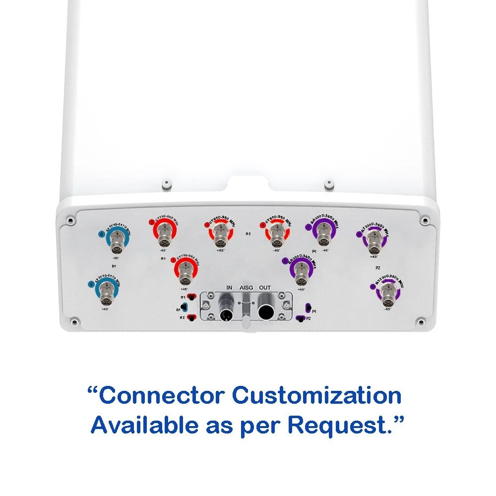
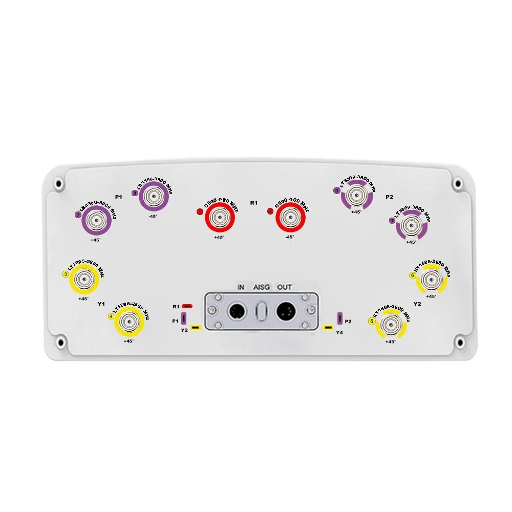
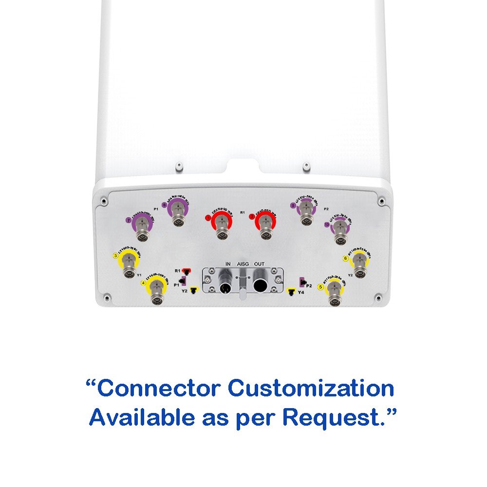
10 RF ports: supports multiple MIMO layers, separate carrier aggregation paths, or independent operator feeds.
Wideband performance: consistent gain and radiation patterns across the full band to simplify network planning and reduce inventory.
High port isolation: minimizes inter-port interference and improves MIMO and carrier-aggregation efficiency.
Sectorization: configurable beamwidth optimized for 65° or 90° sector deployments (specify model/option).
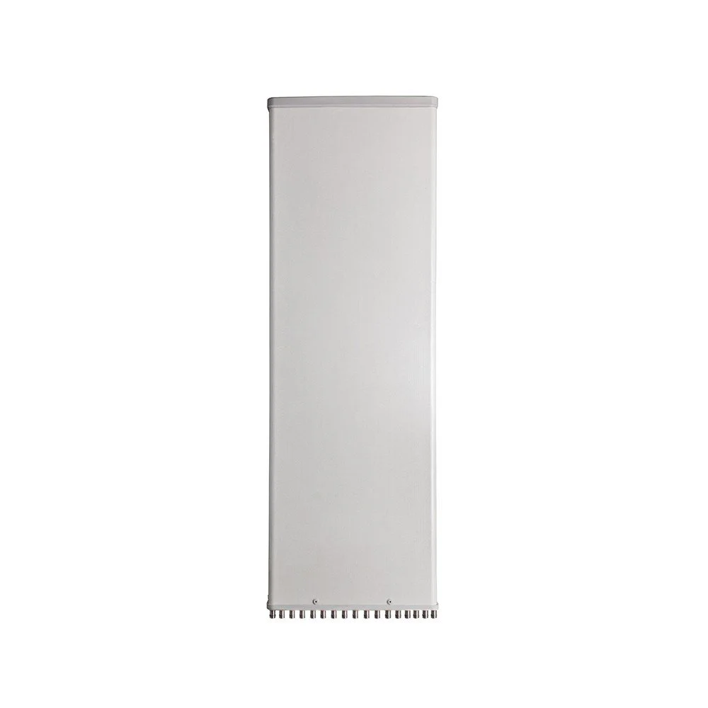
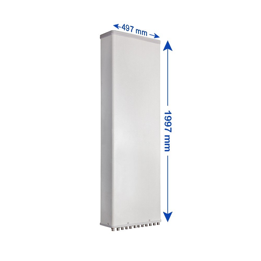
Rugged housing: UV-stable, weatherproof radome and corrosion-resistant mounting hardware for long-term outdoor exposure.
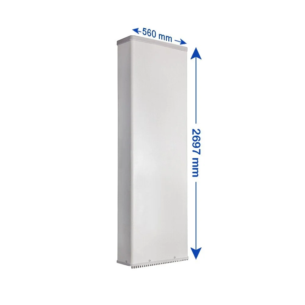
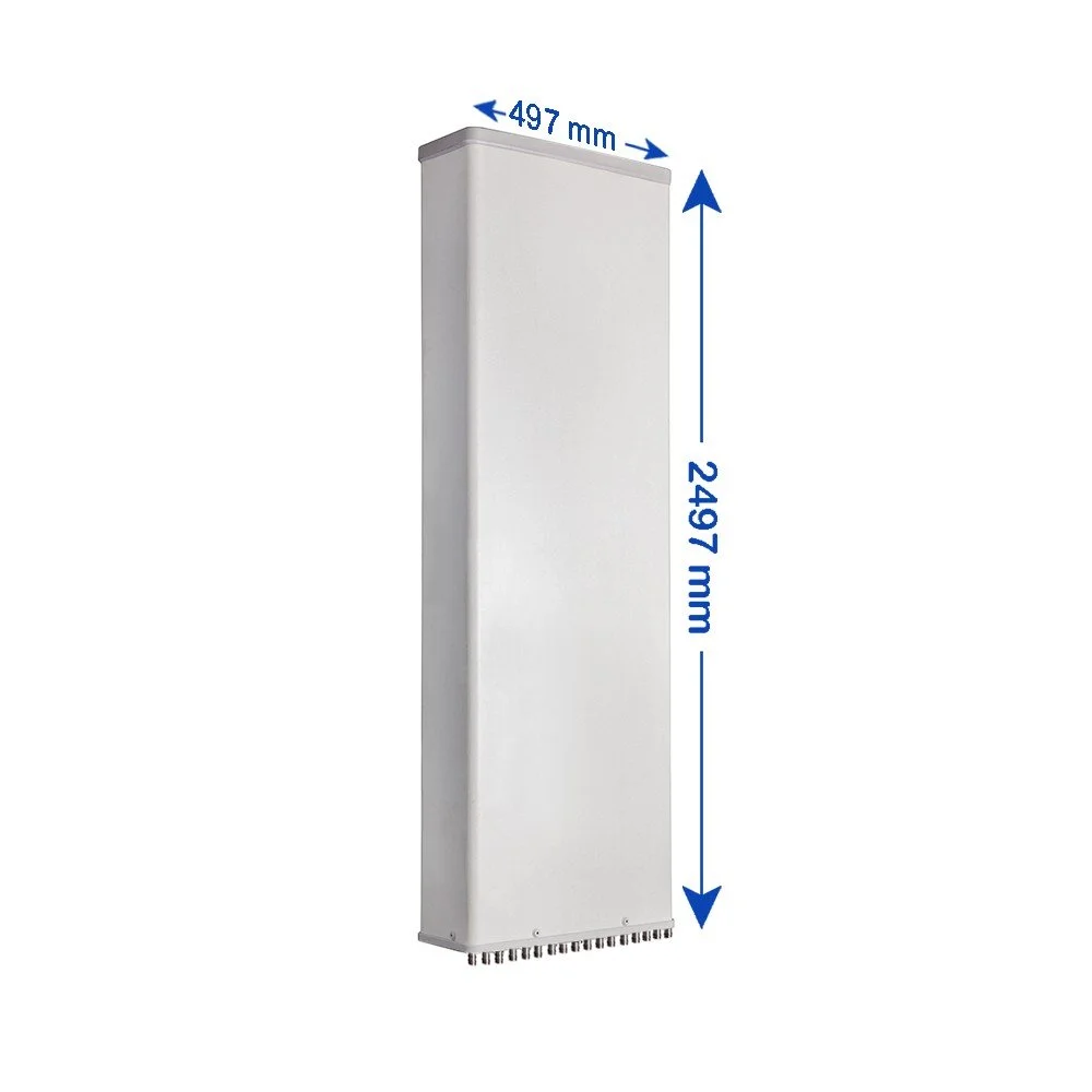
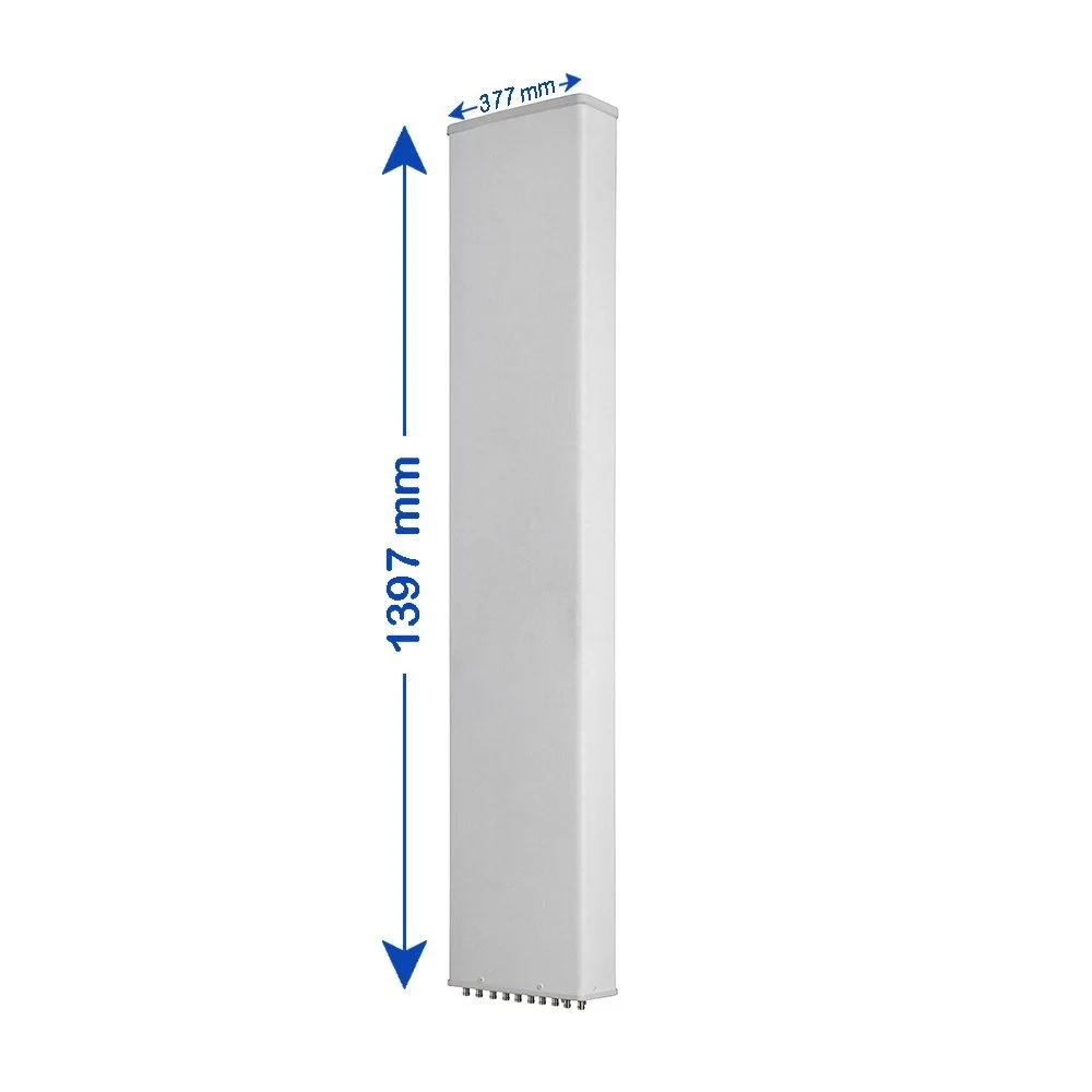
Low wind-load, compact footprint: easier installation on crowded towers and rooftops.
Integrated lightning and surge protection options available (specify when ordering).
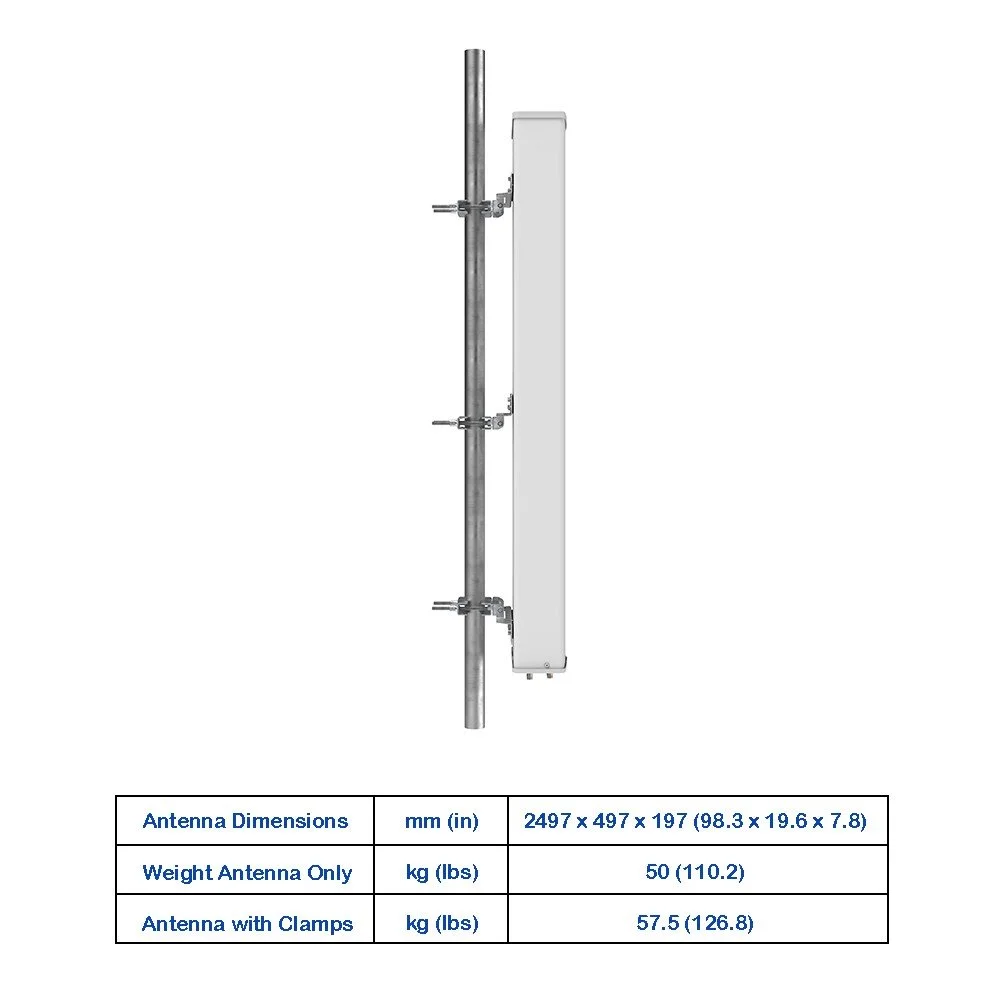
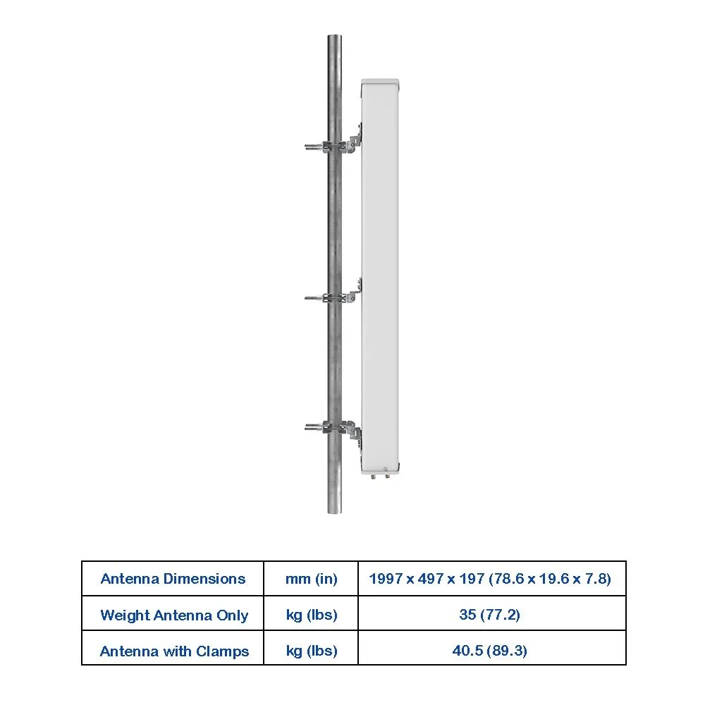
Mounting: universal bracket supports pole and tower mounting; tilt adjustments for electrical and mechanical downtilt.
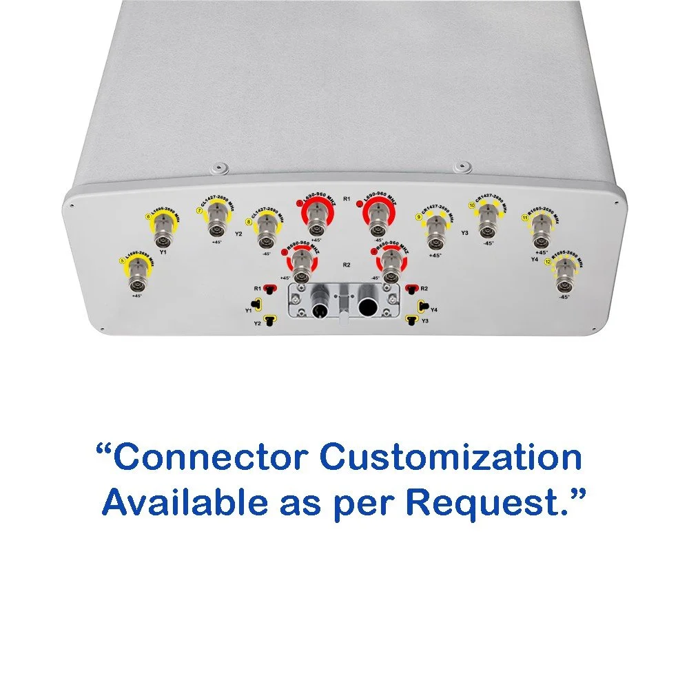
Connector types: industry-standard N-type or 4.3-10 options available per port (specify when ordering).
10-Port Panel Sector Antenna (690–2690 MHz)
Overview :
A high-performance 10-port panel sector antenna engineered for modern multi-operator and multi-band deployments. Covers 690–2690 MHz with industry-leading isolation between ports, compact form factor, and ruggedized housing for reliable outdoor installation. Ideal for dense urban sites, rooftop sectors, and shared tower environments where multiple carriers or technologies (2G/3G/4G/LTE/CBRS) must coexist on a single sector.
Key Features :
Frequency range: 690–2690 MHz continuous coverage for low-band and mid-band cellular and CBRS.
10 RF ports: supports multiple MIMO layers, separate carrier aggregation paths, or independent operator feeds.
Wideband performance: consistent gain and radiation patterns across the full band to simplify network planning and reduce inventory.
High port isolation: minimizes inter-port interference and improves MIMO and carrier-aggregation efficiency.
Sectorization: configurable beamwidth optimized for 65° or 90° sector deployments (specify model/option).
Rugged housing: UV-stable, weatherproof radome and corrosion-resistant mounting hardware for long-term outdoor exposure.
Low wind-load, compact footprint: easier installation on crowded towers and rooftops.
Integrated lightning and surge protection options available (specify when ordering).
Mounting: universal bracket supports pole and tower mounting; tilt adjustments for electrical and mechanical downtilt.
Connector types: industry-standard N-type or 4.3-10 options available per port (specify when ordering).

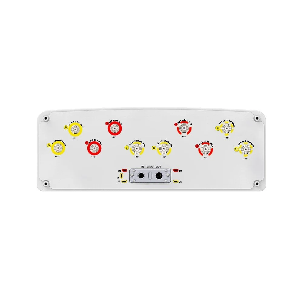 Image 1 of 6
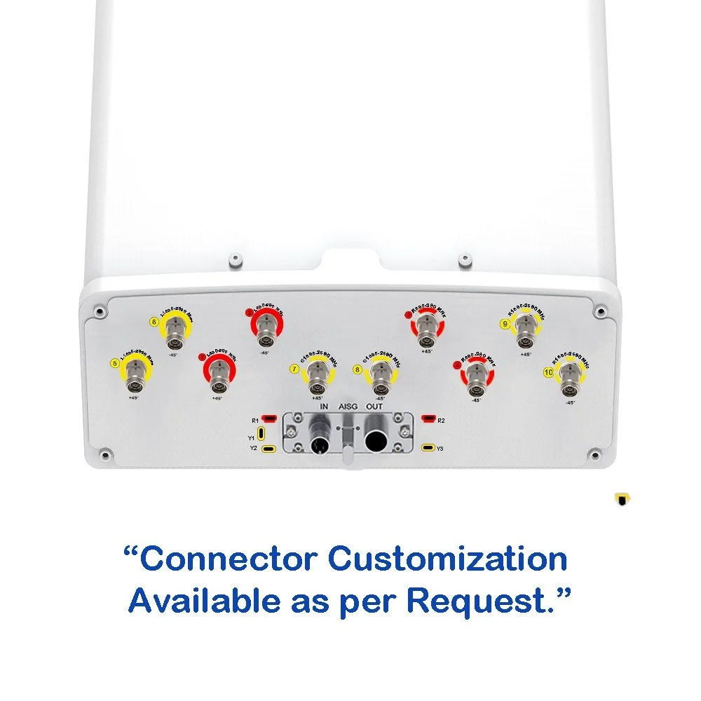 Image 2 of 6
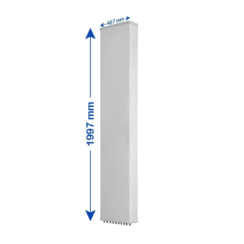 Image 3 of 6
 Image 4 of 6
 Image 5 of 6
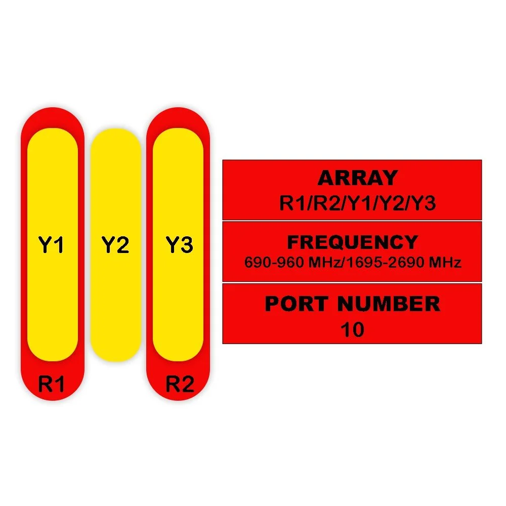 Image 6 of 6