10-Port Hybrid Panel Split‑Beam Sector Antenna (1710–2690 MHz)
Overview :
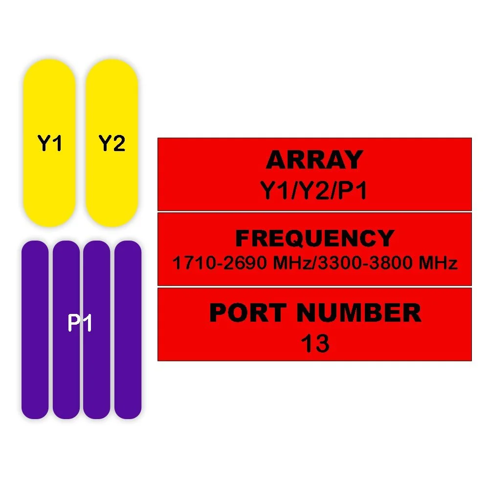
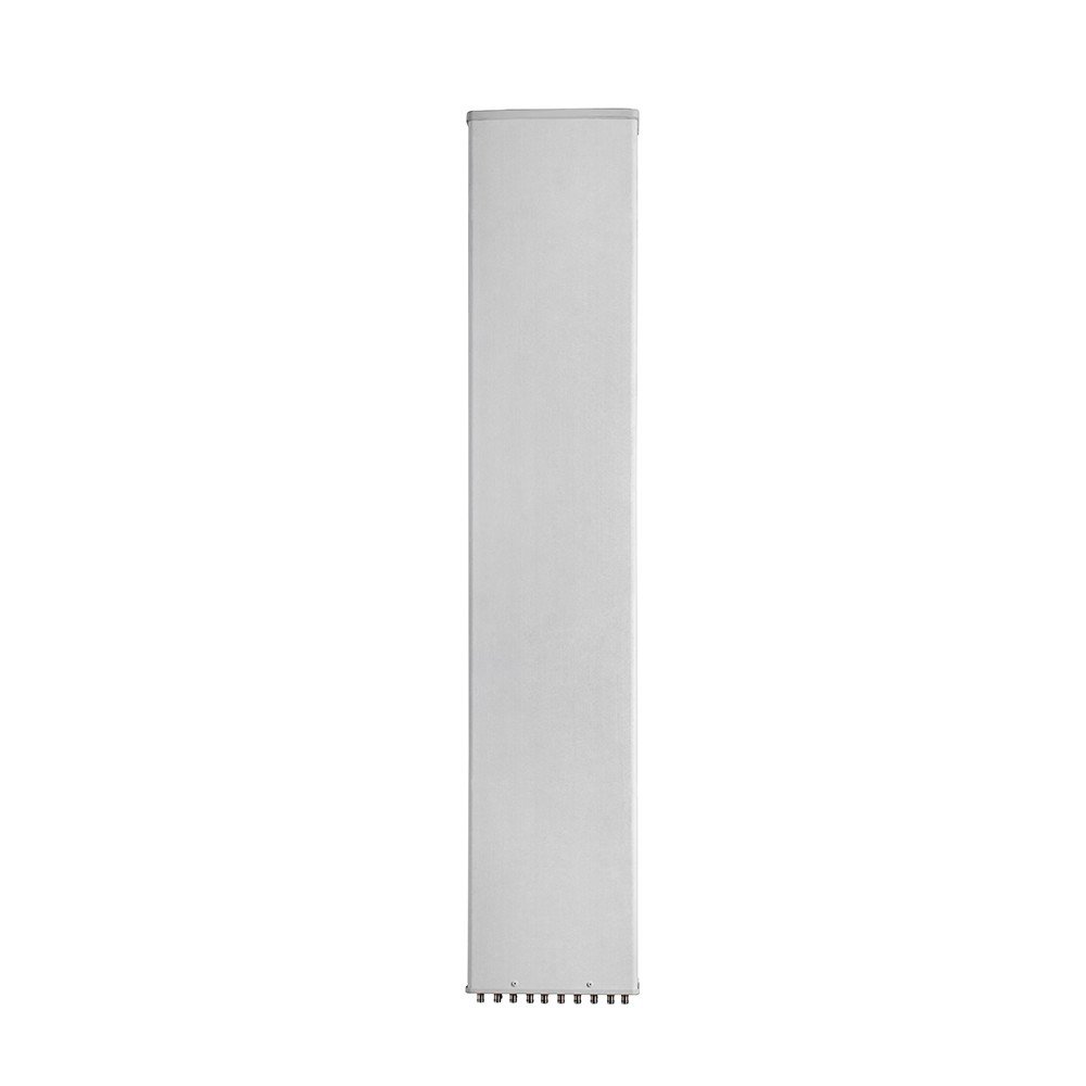
This 10-port hybrid panel split‑beam sector antenna covers 1710–2690 MHz and is engineered for high‑capacity macro sites and dense urban deployments. Its hybrid split‑beam design delivers excellent sector uniformity, superior cross‑polar isolation, and flexible beam tilting options to optimize coverage, capacity, and interference control across LTE and NR mid‑band bands.
Key Features :
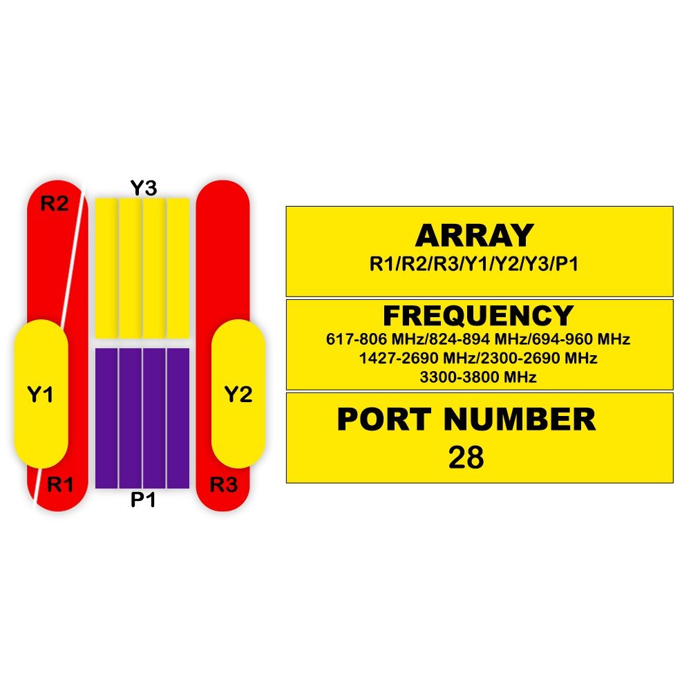
Frequency range: 1710–2690 MHz (full mid‑band support for LTE and 5G NR)
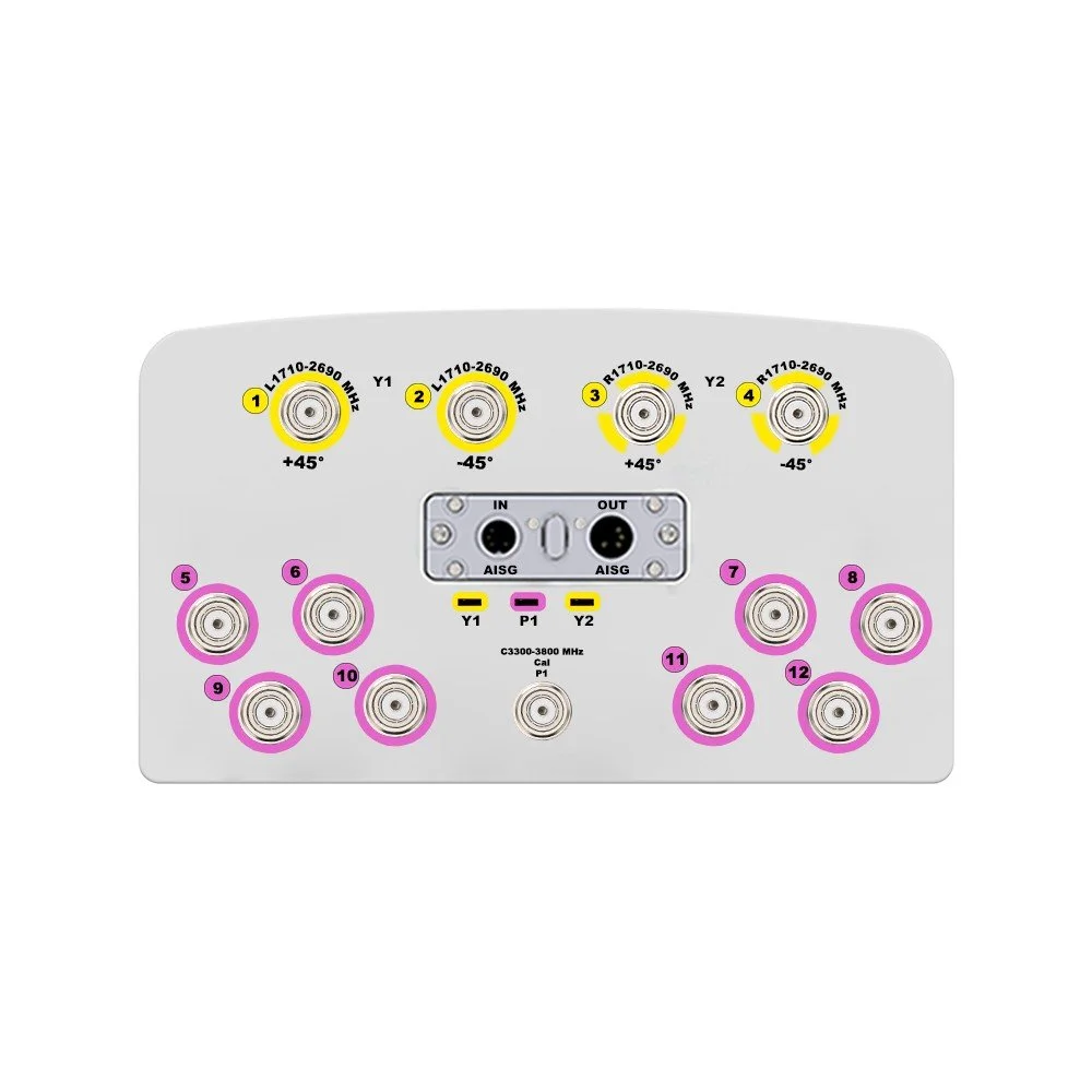
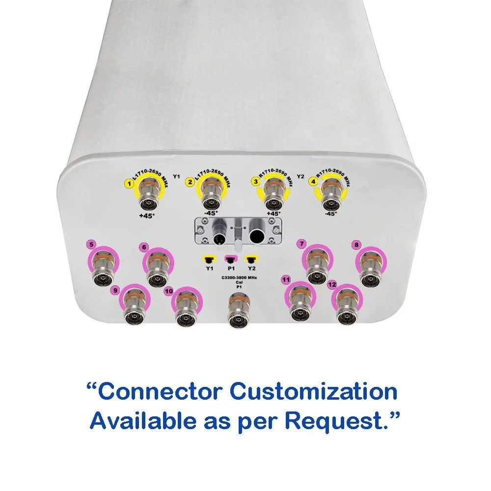
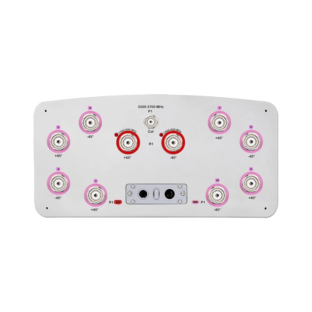
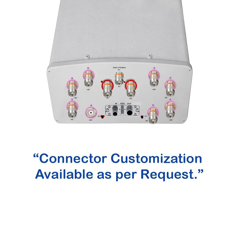
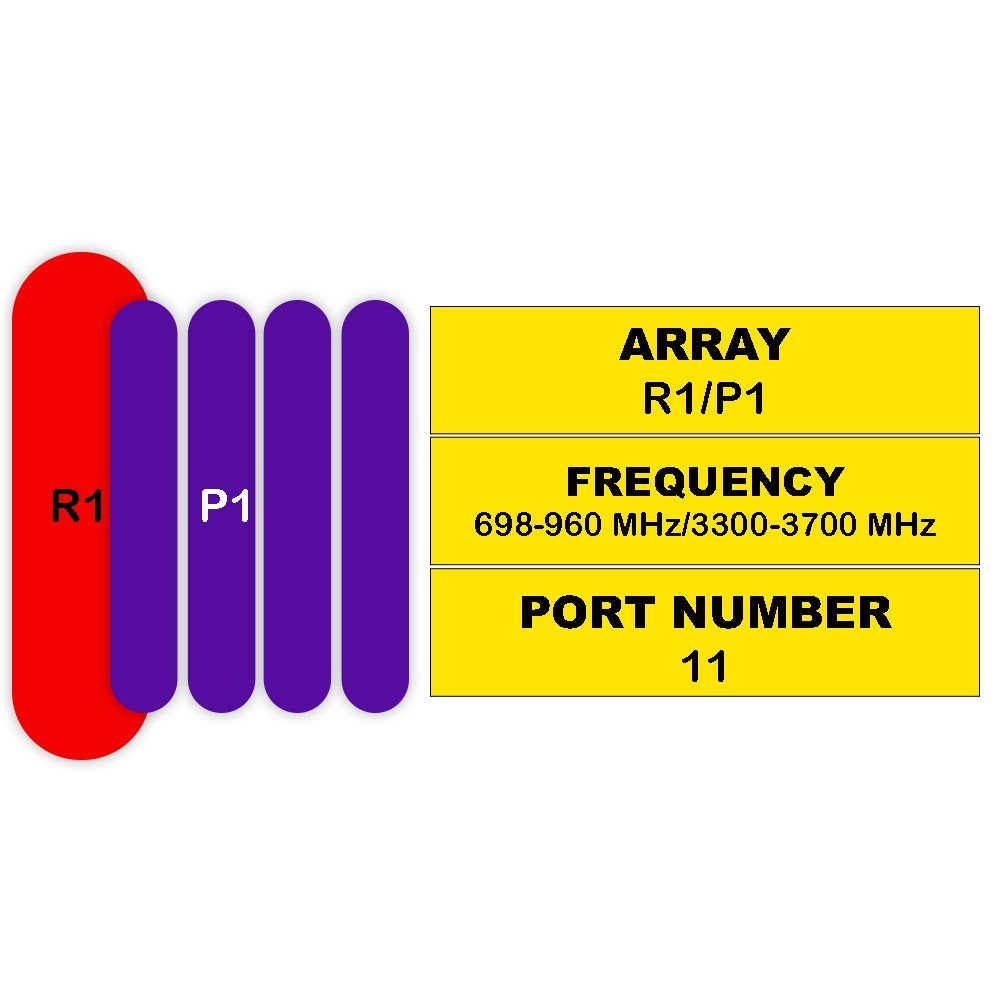
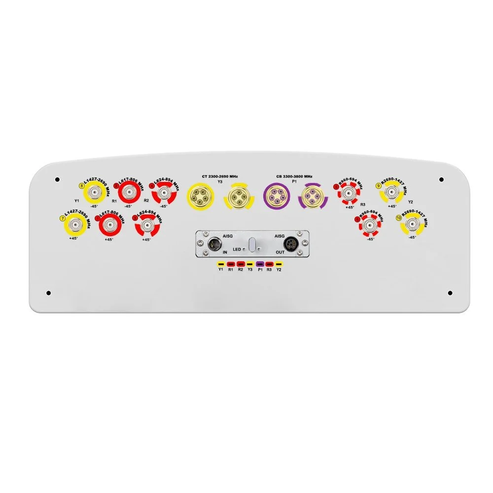
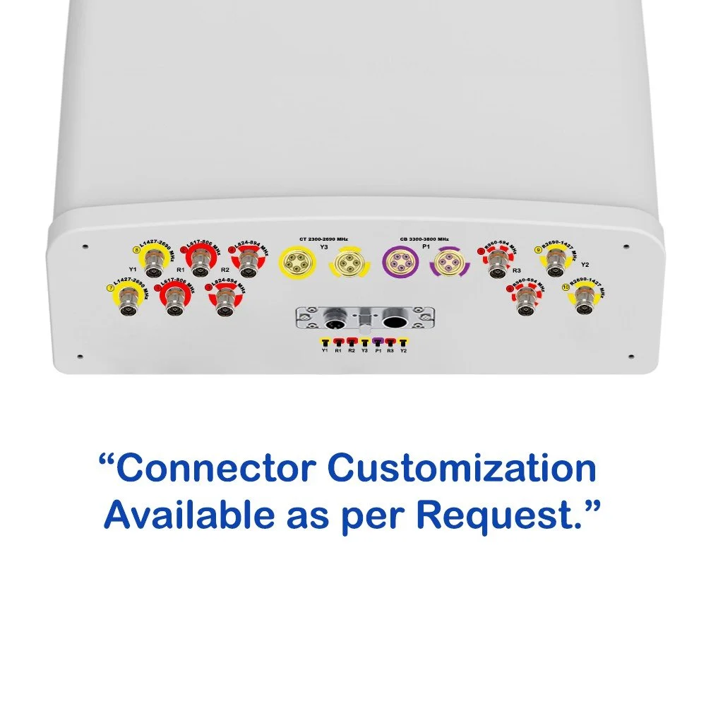
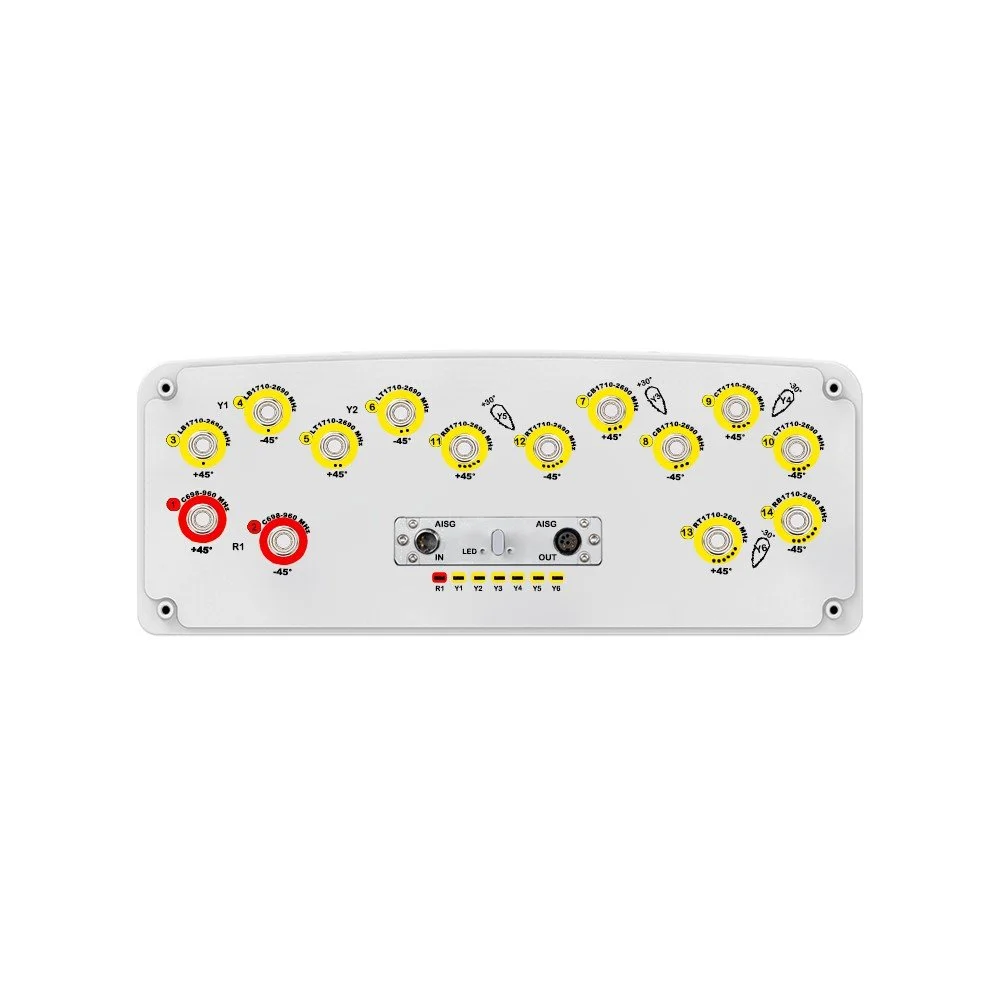
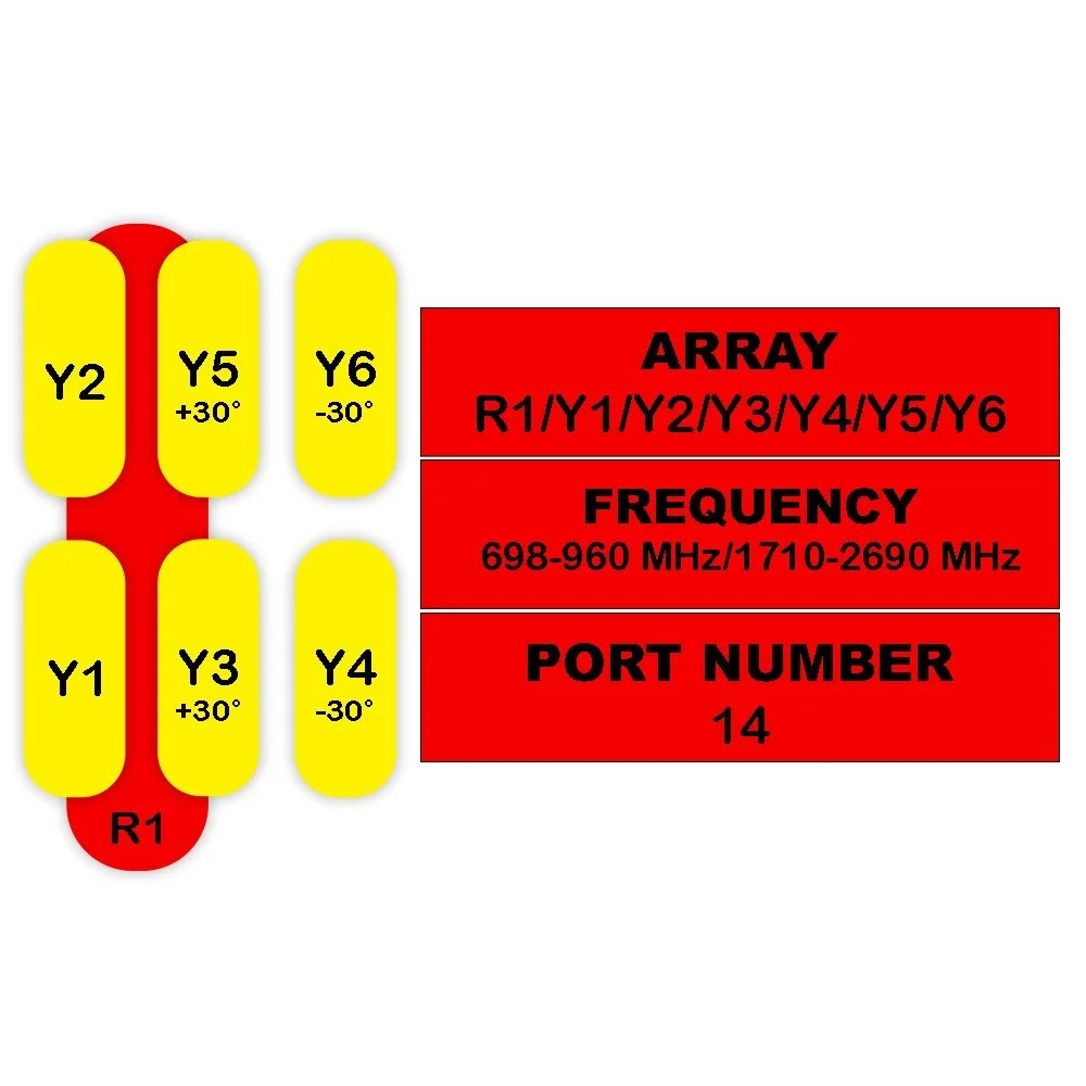
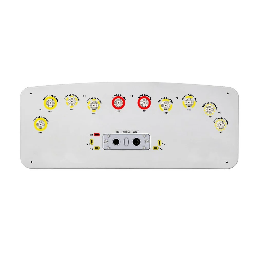
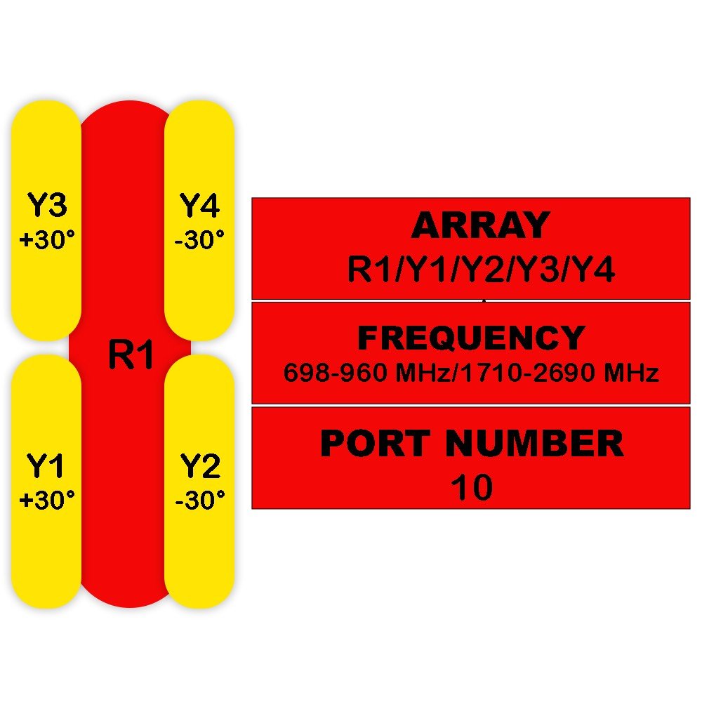
10 RF ports: enables multi‑beam sectorization and advanced MIMO configurations
Hybrid split‑beam architecture: combines narrow azimuth beams for capacity with wider beams for seamless handover and overlap control
Beamwidth (typical): configurable azimuth sectors via port grouping; elevation optimized for 3°–12° electrical tilt
Low sidelobe design: reduces inter‑sector interference and improves SINR at cell edge
High isolation: port-to-port isolation > 30 dB typical to support multi‑operator and multi‑layer deployments
Gain: high and uniform across the band (typical values depend on beam grouping; see ordering options)
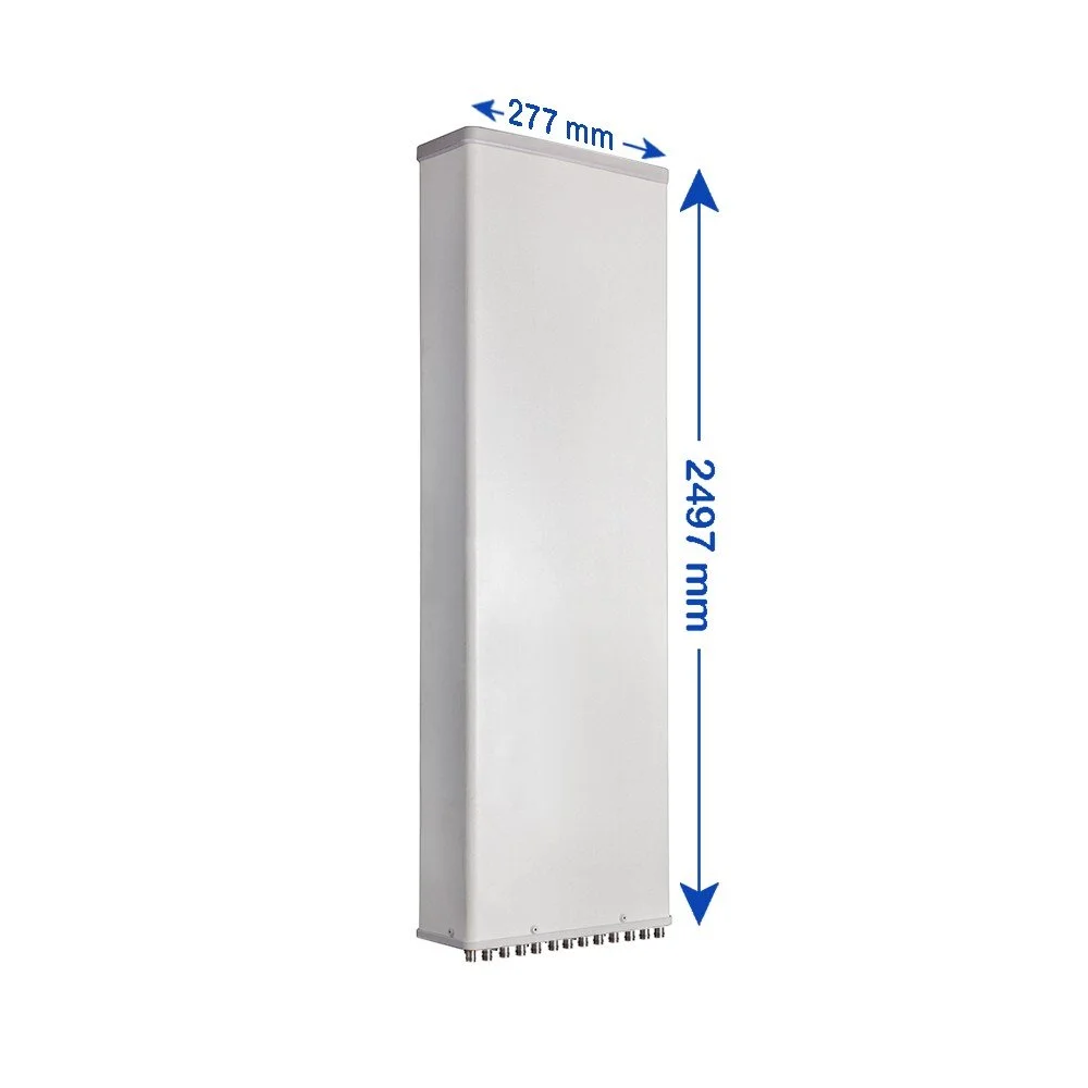
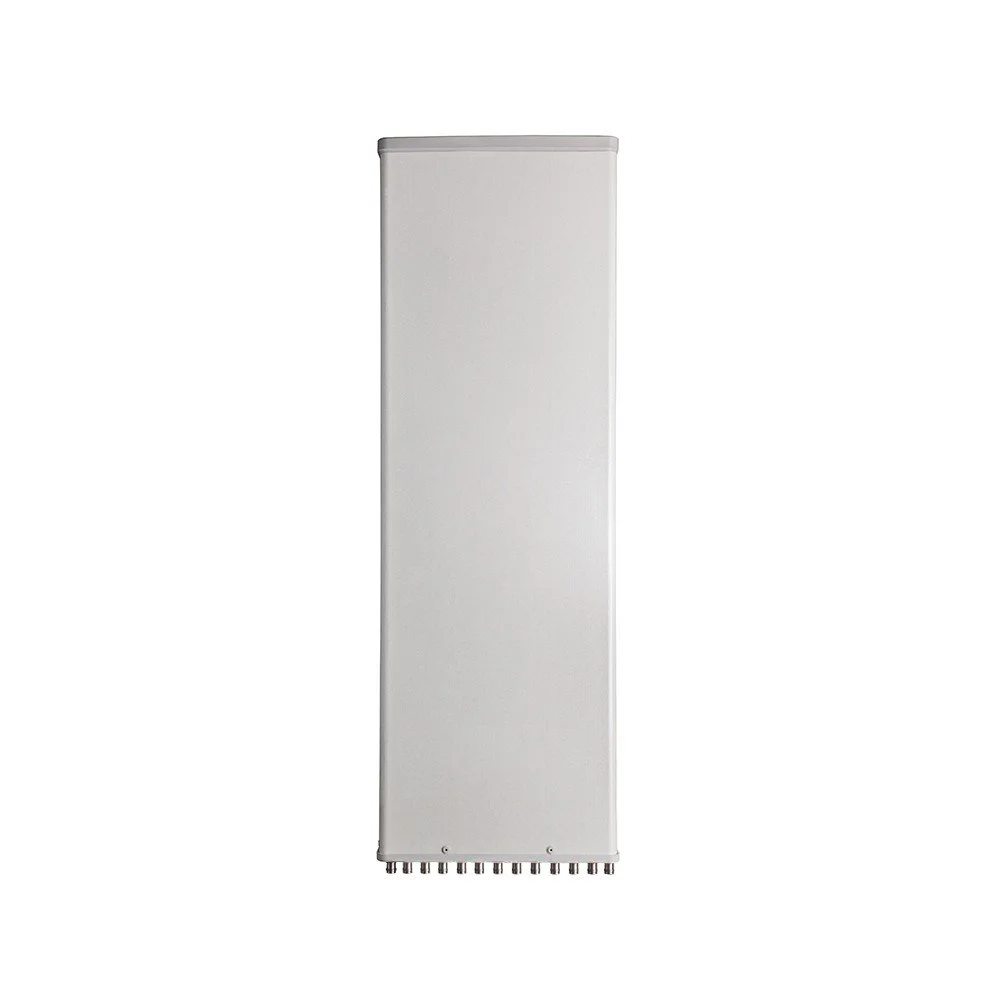
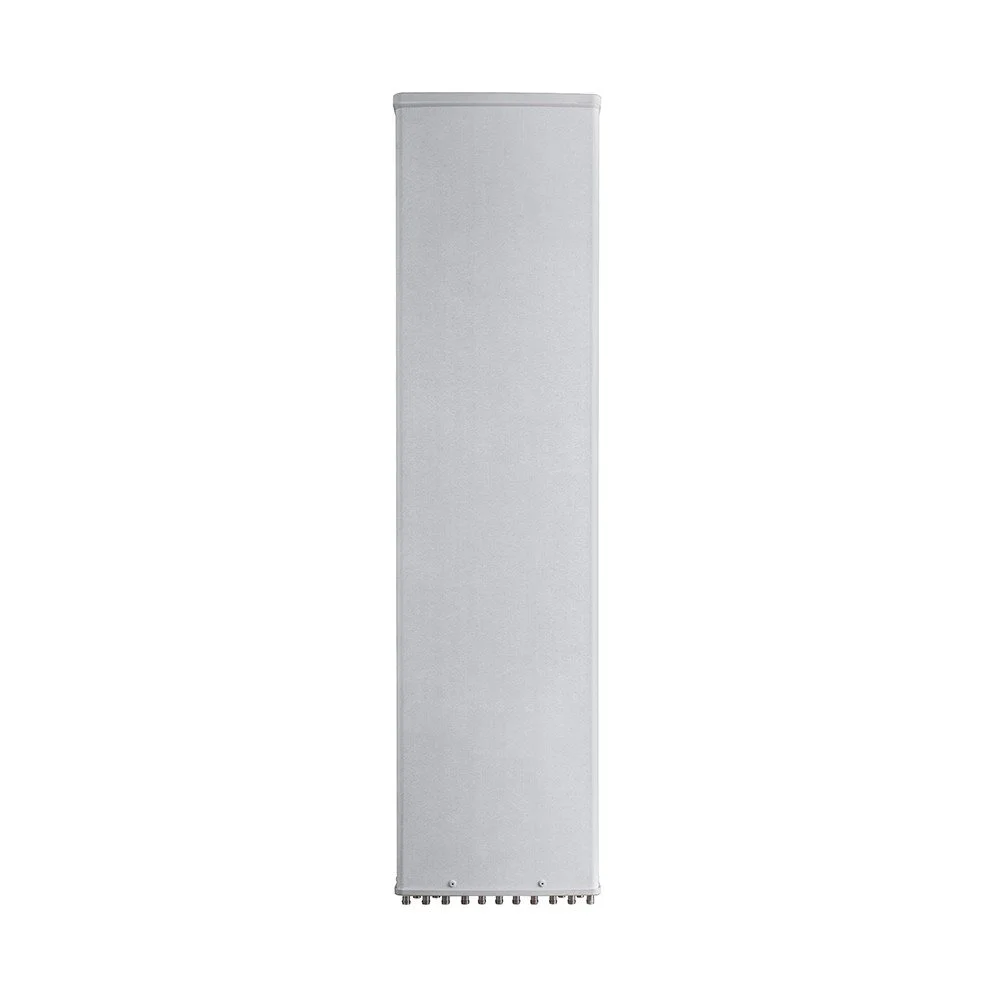
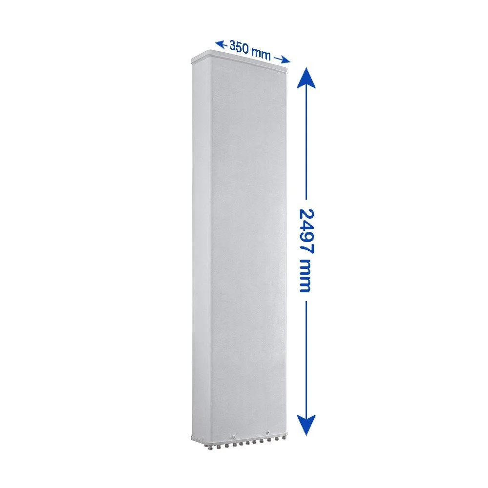
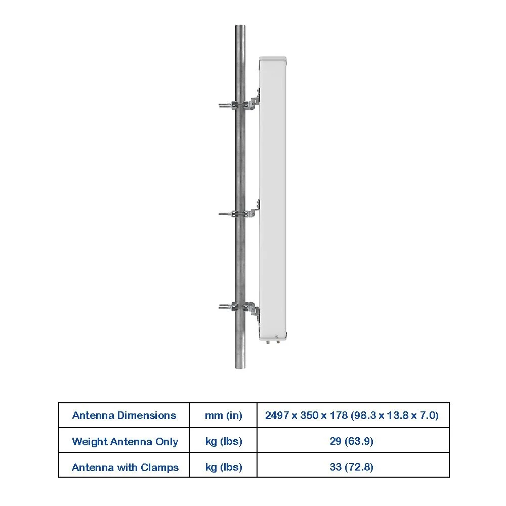
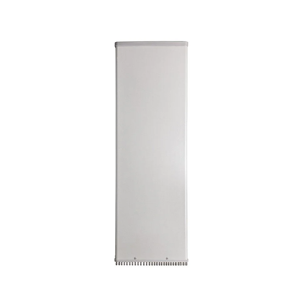
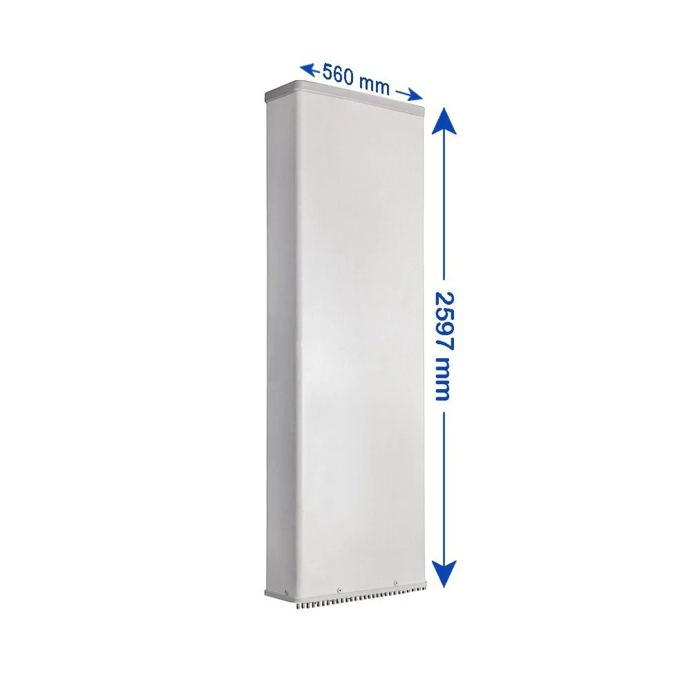
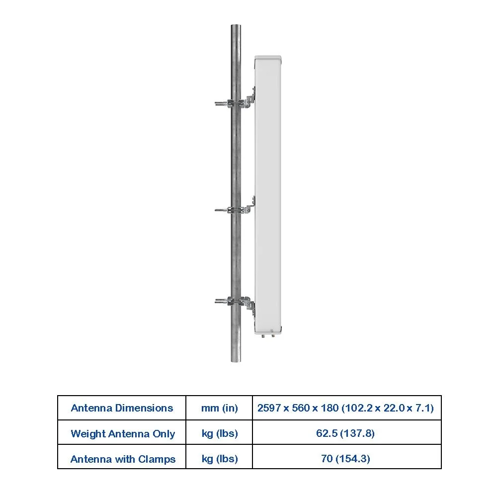
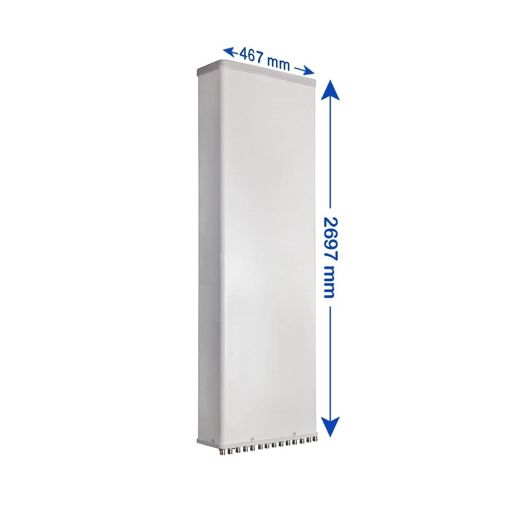
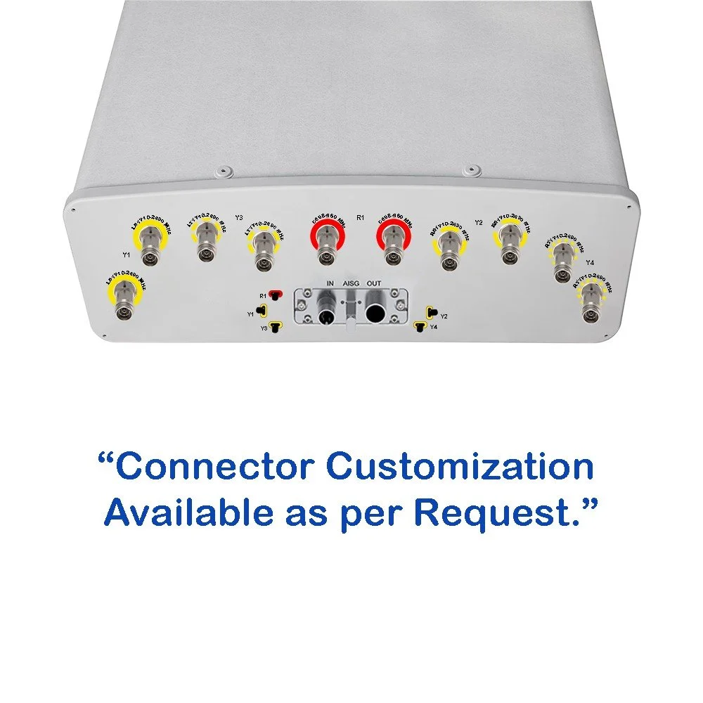
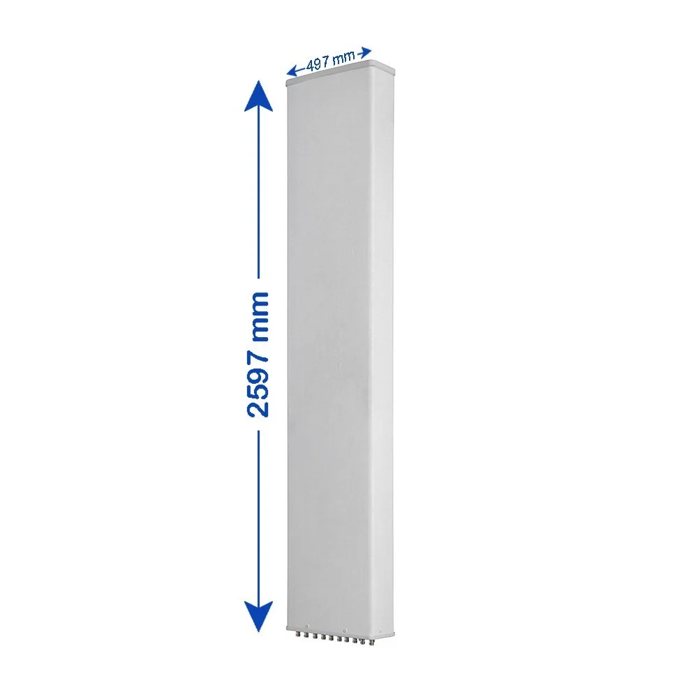
Robust mechanical design: lightweight radome and corrosion‑resistant mounting hardware for rooftop and tower installations
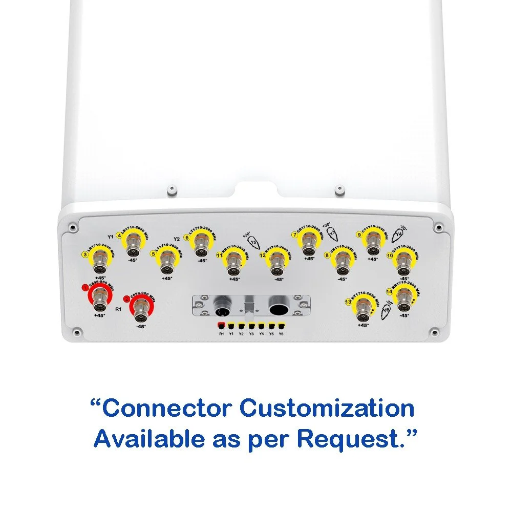
Integrated tilt options: electrical tilt per port plus optional mechanical tilt for rapid optimization
Wideband passive elements: stable performance across full band without retuning
Low passive intermodulation (PIM) construction: suitable for high‑power base stations
10-Port Hybrid Panel Split‑Beam Sector Antenna (1710–2690 MHz)
Overview :
This 10-port hybrid panel split‑beam sector antenna covers 1710–2690 MHz and is engineered for high‑capacity macro sites and dense urban deployments. Its hybrid split‑beam design delivers excellent sector uniformity, superior cross‑polar isolation, and flexible beam tilting options to optimize coverage, capacity, and interference control across LTE and NR mid‑band bands.
Key Features :
Frequency range: 1710–2690 MHz (full mid‑band support for LTE and 5G NR)
10 RF ports: enables multi‑beam sectorization and advanced MIMO configurations
Hybrid split‑beam architecture: combines narrow azimuth beams for capacity with wider beams for seamless handover and overlap control
Beamwidth (typical): configurable azimuth sectors via port grouping; elevation optimized for 3°–12° electrical tilt
Low sidelobe design: reduces inter‑sector interference and improves SINR at cell edge
High isolation: port-to-port isolation > 30 dB typical to support multi‑operator and multi‑layer deployments
Gain: high and uniform across the band (typical values depend on beam grouping; see ordering options)
Robust mechanical design: lightweight radome and corrosion‑resistant mounting hardware for rooftop and tower installations
Integrated tilt options: electrical tilt per port plus optional mechanical tilt for rapid optimization
Wideband passive elements: stable performance across full band without retuning
Low passive intermodulation (PIM) construction: suitable for high‑power base stations

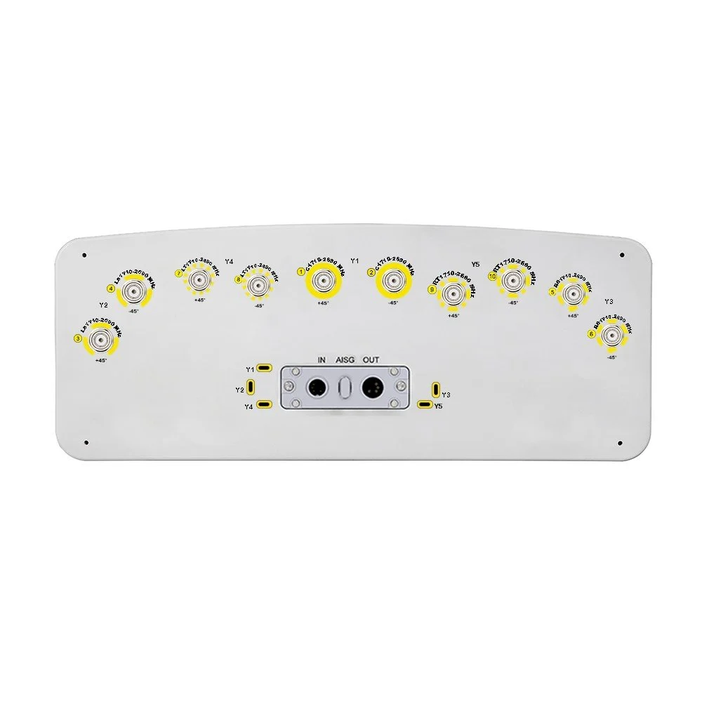 Image 1 of 6
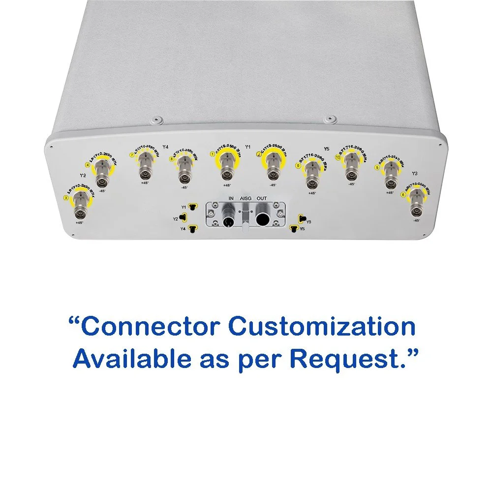 Image 2 of 6
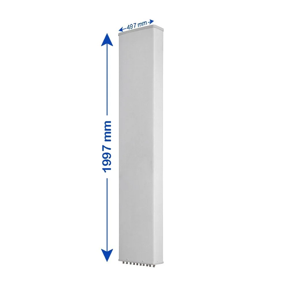 Image 3 of 6
 Image 4 of 6
 Image 5 of 6
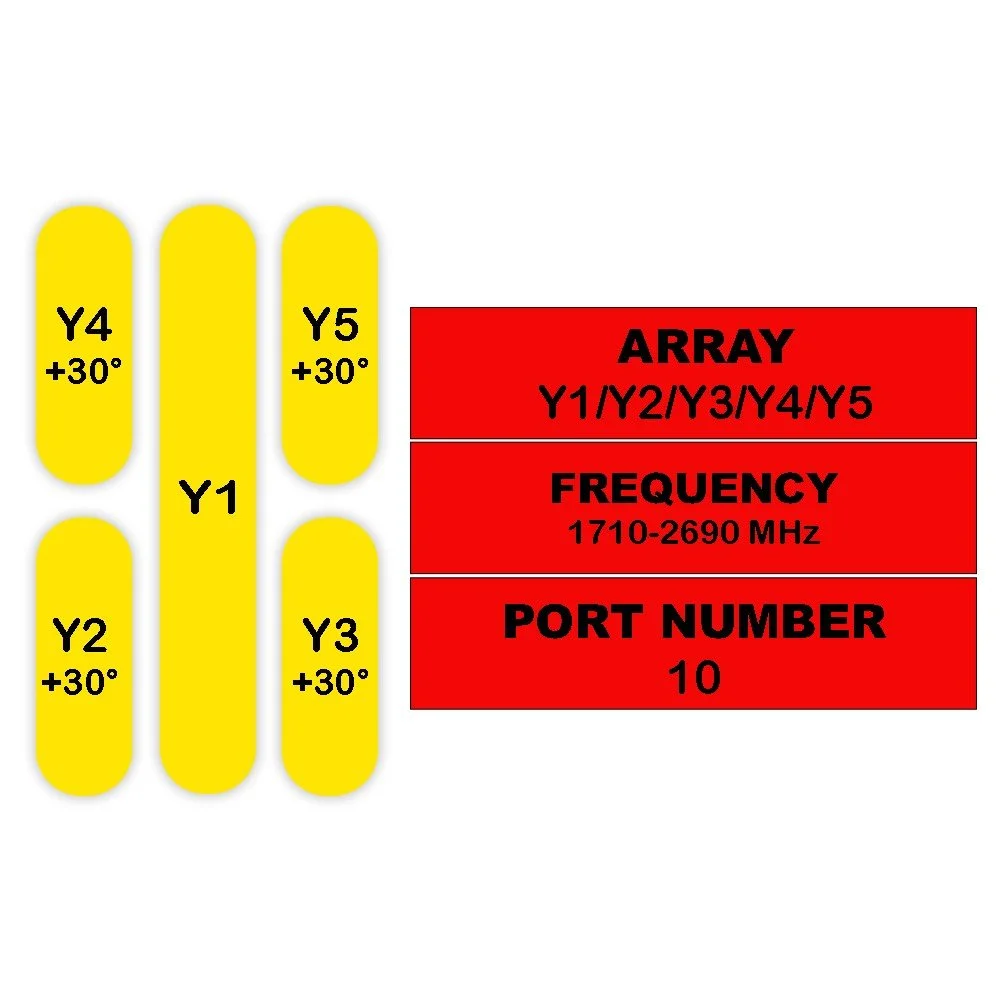 Image 6 of 6